Advertisement
Advertisement
Table of Contents

Related Manuals for Hollyland MARS 400S


Summary of Contents for Hollyland MARS 400S
- Page 1 MARS 400S User Manual Version 1.2.0...
-
Page 2: Key Features
DESCRIPTION Thank you for purchasing Hollyland MARS 400S wireless HD video transmission system. The product uses the latest coding, decoding technology and 5G wireless transmission technology and can achieve ultra-low latency wireless video transmission. It has a transmission range over 400ft with a clean line of sight (LOS), supports up to 1080P 60Hz image resolution, and in the end achieves full HD HDMI/SDI video transmission. -
Page 3: Packing List
PACKING LIST ① ② ③ ④ ⑤ ⑥ ⑦ ⑧ ⑨ ① Transmitter ② Receiver ③ Antenna ④ Quick Guide ⑤ Cold Shoe ⑥ Expansion Accessory ⑦ DC Adapter ⑧ USB Type-C to Type-A OTG Adapter ⑨ C-Shaped Screw... -
Page 4: Typical Setup
TYPICAL SETUP HDMI/SDI IN HDMI/SDI OUT T h i s w i r e l e s s H D v i d e o t r a n s m i s s i o n s y s t e m u s e s t h e l a t e s t w i r e l e s s communication technology and transmits ultra-low latency HD video. -
Page 5: Product Interfaces
PRODUCT INTERFACES ① ① ② ② ⑥ ⑥ ⑦ ⑦ ⑧ ⑧ ③ ③ ⑨ ⑨ ④ ④ ⑩ ⑩ ⑤ ⑪ ⑤ ⑪ ⑫ ⑫ TRANSMITTER RECEIVER ① ① Antenna Interface (RP-SMA Male) Antenna Interface (RP-SMA Male) ② ② Fan Air Outlet Fan Air Outlet ③... -
Page 6: Vertical Installation
INSTALLATION ① ③ ② ④ VERTICAL INSTALLATION ① Install the antennas as demonstrated ② Secure the cold shoe with 1/4 screw hole at the bottom of the transmitter and mount it to the camera ③ Connect to a power supply (Compatible with NP-F970 or the same series of batteries) ④... -
Page 7: Horizontal Installation
INSTALLATION ① ④ ② ③ ⑤ HORIZONTAL INSTALLATION ① Install the antennas as demonstrated ② Connect the expansion accessary with the 1/4 screw hole at the bottom of the transmitter by a C-shaped screw ③ Secure the cold shoe with the 1/4 screw hole on the expansion accessary and install them on the camera ④... -
Page 8: Oled Display
OLED DISPLAY ① ① ⑤ ② ② ⑥ ⑤ 4E0657C 4E0657C ③ ③ ⑥ ④ ④ ⑦ ⑦ ⑧ ⑧ TRANSMITTER RECEIVER ① ① Device ID Device ID ② ② Scene Mode Scene Mode ③ ③ USB Flash Detection Indicator USB Flash Detection Indicator ④... -
Page 9: Status Description
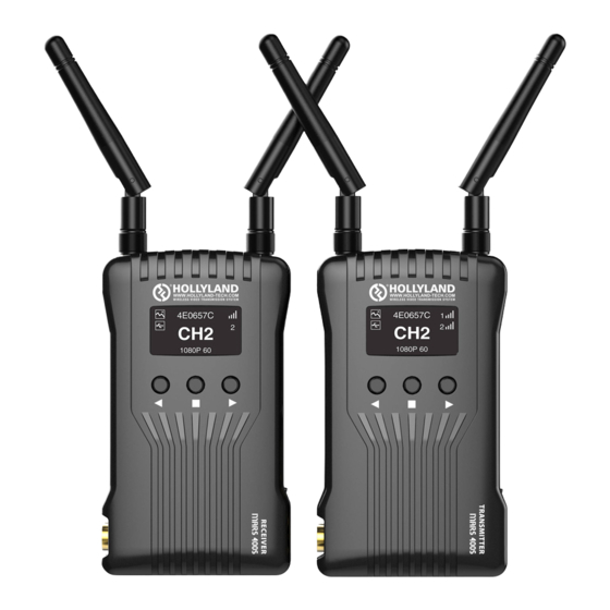
STATUS DESCRIPTION 4E0657C 4E0657C 4E0538D NO VIDEO 1. When the devices are disconnected, a cross “x” will appear above the signal strength bars on both the transmitter and the receiver. As shown in the above picture, device 1 is on connected status, while device 2 is on disconnected status. - Page 10 STATUS DESCRIPTION 4E0657C 4E0657C 3. When the device detects a connection to a USB flash, the USB flash detection Indicator will light up. 4. When the voltage is too low, the low battery alarm will be triggered and the low- battery icon will flash slowly.
- Page 11 QUICK GUIDE SCENE MODE IMAGE MODE BALANCE MODE SPEED MODE SYSTEM SETTING SCENE MODE LANGUAGE SYSTEM SETTING PAIR VERSION INFO RETURN EXIT VERSION INFO B0411DE0657C V1.0.2.0 RETURN TRANSMITTER 1. Long press the “MENU” button for about 3 seconds to enter the root menu interface.
- Page 12 QUICK GUIDE × √ √ √ √ √ √ × √ × √ √ √ RETURN SYSTEM SETTING CHANNEL SCAN LANGUAGE SYSTEM SETTING PAIR VERSION INFO RETURN EXIT VERSION INFO B0412D8F5CA5 V1.0.2.0 RETURN RECEIVER 1. Press the “MENU” button for about 3 seconds to enter the root menu interface. The root menu has “CHANNEL SCAN”, “SYSTEM SETTING”...
-
Page 13: Channel Change
QUICK GUIDE CHANNEL CHANGE Press the channel button “UP/DOWN” on the transmitter or the receiver to change the current channel. Press “OK” to confirm the channel number, then the channel of the transmitter and the receiver will be synchronously and automatically changed. DEVICE UPGRADE 1. - Page 14 QUICK GUIDE IOS & ANDROID APP MONIRTORING Android System Installation and Use 1. The application name is “HollyView”. It is available on Hollyland's official website and Android APP store. 2. Method No.1 Scan the QR code on the back of the transmitter then the APP will be automatically connected to the device.
- Page 15 PARAMETERS Transmitter Receiver HDMI Input (Type A Female) HDMI Output (Type A Female) SDI Input SDI Output Interface 2 Antenna Interfaces (RP-SMA Male) 2 Antenna Interfaces (RP-SMA Male) DC Input, Type-C USB DC Input, Type-C USB Supply Interface 6~16V DC 6~16V DC Power Consumption <11W...
-
Page 16: Connection Issues
CONNECTION ISSUES 1. Check and make sure that the power supply works fine on both the transmitter and the receiver. 2. If the device displays with the low-battery sign, change or charge the battery in time. 3. Try to change to another channel and to connect the devices again for there might be interference for the current channel. - Page 17 L IMAGE LOW QUALITY ISSUES 1. Set “SCENE MODE” to “IMAGE MODE”. 2. Check if the HDMI/SDI IN or OUT cables are correctly connected. 3. Make sure both the transmitter and the receiver are installed at least 1.5m above the ground. 4.
- Page 18 HollylandTech HollylandTech HollylandTech sales@Hollyland-tech.com www.hollyland-tech.com...
Need help?
Do you have a question about the MARS 400S and is the answer not in the manual?
Questions and answers