Table of Contents
Advertisement
Quick Links
SD Card real time data recorder
%RH, Light, Anemometer, Temp, all in one
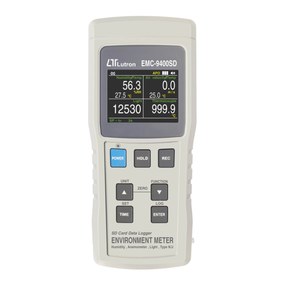
ENVIRONMENT METER
Model : EMC-9400SD
Your purchase of this ENVIRONMENT METER marks a step forward for
you into the field of precision measurement. Although this Meter is a
complex and delicate instrument, its durable structure developed. Please
read the following instructions carefull yand always keep this manual
within easy reach.
OPERATION MANUAL
Advertisement
Table of Contents

Related Manuals for Lutron Electronics EMC-9400SD


Summary of Contents for Lutron Electronics EMC-9400SD
- Page 1 SD Card real time data recorder %RH, Light, Anemometer, Temp, all in one ENVIRONMENT METER Model : EMC-9400SD Your purchase of this ENVIRONMENT METER marks a step forward for you into the field of precision measurement. Although this Meter is a complex and delicate instrument, its durable structure developed.
-
Page 2: Table Of Contents
TABLE OF CONTENTS 1. FEATURES......................2. SPECIFICATIONS....................3. FRONT PANEL DESCRIPTION................4. MEASURING PROCEDURE................4-1 Function selection ....................4-2 Anemometer/Temp. measurement................ 4-3 Humidity/Temp. measurement................4-4 Type K/J Temperature measurement..............4-5 Light measurement....................4-6 Data Hold......................4-7 Data Record ( Max./ Min. reading )..............4-8 LCD brightness select................... -
Page 3: Features
1. FEATURES * Environment instrument, multi-function, all in one. * Type K/J thermometer, Humidity/Temp. meter, Anemometer, Light meter. * Humidity measurement can show %RH and Temp., Dew , Wet Temp. * Anemometer can default the display unit to m/S, FPM, Km/h, mph, knot. -
Page 4: Specifications
2. SPECIFICATIONS 2-1 General Specifications Circuit Custom one-chip of microprocessor LSI circuit. Display TFT LCD size : 2.4 " Measurement * Anemometer with Temp.,CMM,CFM function * Humidity/Temp. meter,DEW ,WET * Light meter * Type K/J thermometer Datalogger Auto 1 second to 3600 seconds Sampling Time @ For anemometer measurement, Setting range... - Page 5 Temperature Automatic temp. compensation for the Compensation Anemometer function and the type K/J thermometer. Data Hold Freeze the display reading. Memory Recall Maximum & Minimum value. Sampling Time Approx. 1 second. of Display Data Output RS 232/USB PC computer interface. * Connect the optional RS232 cable UPCB-02 will get the RS232 plug.
- Page 6 Optional Accessories * SD Card ( 4 G ) * Type K thermocouple probe. TP-02A. TP-03, TP-04 * AC to DC 9V adapter. * USB cable, USB-01. * RS232 cable, UPCB-02. * Data Acquisition software,SW-U801-WIN. ℃ 2-2 Electrical Specifications (23±5 Anemometer A.
- Page 7 Measurement Area CMM ( m^3/min. ) 0.001 to 30.000 m^2 CFM ( ft^3/min. ) 0.01 to 322.93 ft^2 Humidity/Temp. meter A. Humidity Measuring Range 0 % to 95 % R.H. Resolution 0.1 % R.H. ≧70% RH : Accuracy ±(3% reading + 1% RH). <...
- Page 8 Wet bulb ( Humidity ) Range -21.6 ℃ to 50.0 ℃ ℃ 0.1 ℃ Resolution Range -6.9 ℉ to 122.0 ℉. ℉ 0.1 ℉. Resolution Remark : * Wet bulb display value is calculated from the Humidity/Temp. measurement automatically. * The Welt bulb accuracy is sum accuracy value of Humidity &...
-
Page 9: Front Panel Description
3. FRONT PANEL DESCRIPTION Fig. 1... - Page 10 3-1 Display 3-2 Power Button ( LCD Brightness adjustment ) 3-3 Hold Button 3-4 REC Button 3-5 ▲ Button (Unit Button ) 3-6 ▼ Button ( Function Button ) 3-7 TIME Button ( SET Button ) 3-8 ENTER ( LOG Button ) 3-9 SD card socket 3-10 RS-232 Output Terminal 3-11 Reset Button...
-
Page 11: Measuring Procedure
4. MEASURING PROCEDURE 4-1 Function selection 1) Turn on the meter by pressing the " Power Button " ( 3-2, Fig. 1 ) momentarily. Pressing the " Power Button " ( 3-2, Fig. 1 ) continuously and > 2 seconds again will turn off the meter. -
Page 12: Anemometer/Temp. Measurement
4-2 Air velocity/Temp. measurement 1) Function select to " Air velocity/Temp. " measurement. 2) Plug the " Probe Plug " ( 3-27, Fig. 1 ) into the " Probe Input Socket " ( 3-19, Fig. 1 ). Power on the meter by pressing the " Power Button " ( 3-2, Fig. -
Page 13: Humidity/Temp. Measurement
4-3 Humidity and Temperature measurement 1) Function select to " Humidity/Temp. " measurement. Plug the " Probe Plug " ( 3-30, Fig. 1 ) into the " Probe Input Socket " ( 3-18, Fig. 1 ). 2) Power on the meter by pressing the " Power Button " ( 3-2, Fig. -
Page 14: Light Measurement
Change the temperature unit ( ℃, ℉ ) If intend to change the Temp. display unit, select to the Type K/J Thermometer function only,then press the "Unit Button " ( 3-5, Fig.1) continuously,the unit will change from " ℃ " to "... -
Page 15: Data Hold
Zero adjustment During the Light measurement, use the light sensor cover ( 3-21 Fig.1) blank the Light Sensor ( 3-22, Fig. 1 ) completely, if the Display is not show zero value, together press the " ▲ Button " (3-5, Fig. 1 ) & " ▼ Button " (3-6, Fig. 1 ) >... -
Page 16: Lcd Brightness Select
b) Press the " REC Button " ( 3-4, Fig. 1 ) again, the " REC MIN " symbol along with the minimum value will appear on the display. If intend to delete the minimum value, just press the " Hold Button " ( 3-3, Fig. 1 ) once, then the display will show the "... -
Page 17: Datalogger
5. DATALOGGER 5-1 Preparation before execute datalogger function a. Insert the SD card Prepare a " SD memory card " ( 1 G to 16 G, optional ), insert the SD card into the " SD card socket " ( 3-9, Fig. 1). The front panel of the SD card should face against the down case. -
Page 18: Auto Datalogger( Set Sampling Time ≧ 1 Second )
≧ 5-2 Auto Datalogger ( Set sampling time 1 second ) a. Start the datalogger Press the " LoggerButton ( 3-8, Fig. 1 ) > 2 Sec. , the LCD will show the text " LOGGER ", and flashing , at the same time the measuring data along the time information will be saved into the memory circuit. -
Page 19: Manual Datalogger ( Set Sampling Time = 0 Second )
5-3 Manual Datalogger ( Set sampling time = 0 second ) a. Set sampling time is to 0 second Press the " Logger Button ( 3-8, Fig. 1 ) >2 Sec. , the LCD will show the text " Logger ", then press the " Logger Button " ( 3-8, Fig. -
Page 20: Sd Card Data Structure
5-5 SD Card Data structure 1) When the SD card is used into the meter, the SD card When the first time, the SD card is used into the meter, the SD card will generate a folder : EMC01 2) If the first time to execute the Datalogger, under the route EMC01\, will generate a new file name EMC01001.XLS. -
Page 21: Saving Data From The Sd Card To The Computer
6. Saving data from the SD card to the computer ( EXCEL software ) 1) After execute the Data Logger function, take away the SD card out from the " SD card socket " ( 3-9, Fig. 1 ). 2) Plug in the SD card into the Computer's SD card slot ( if your computer build in this installation ) or insert the SD card into the "... -
Page 22: Advanced Setting
EXCEL graphic screen ( for example ) 7. ADVANCED SETTING Under do not execute the Datalogger function, press the " SET Button " ( 3-7, Fig. 1 ) continuously at least two seconds will enter the " Advanced Setting " mode. then press the "... -
Page 23: Set Clock Time ( Year/Month/Date, Hour/Minute/ Second )
Remark : During execute the " Advanced Setting " function, if press " Power Button " ( 3-2, Fig. 1 ) once will exit the " Advanced Setting " function, the LCD will return to normal screen. 7-1 Set clock time ( Year/Month/Date, Hour/Minute/ Second ) When the lower display show "... -
Page 24: Set Beeper Sound On/Off
2) After select the upper text to " YES " or " NO ", press the " Enter Button " ( 3-8, Fig. 1 ) will save the setting function with default and Back to " Advanced Setting screen ". 7- 3 Set beeper sound ON/OFF When the lower display show "... -
Page 25: Select The Temperature Type K/J
When the lower display show " DECIMAL POINT " 1) Use the " ▲ Button " ( 3-5, Fig. 1 ) or " ▼ Button " ( 3-6, Fig. 1 ) to select the display text to " USA " or "... -
Page 26: Sd Memory Card Format
7-8 SD memory card Format When the lower display show " SD FORMAT " 1) Use the " ▲ Button " ( 3-5, Fig. 1 ) or " ▼ Button " ( 3-6, Fig. 1 ) to select the display text to " YES " or " NO ". YES - Intend to format the SD memory card NO - Not execute the SD memory card format 2) If select the upper to "... -
Page 27: Power Supply From Dc Adapter
8. POWER SUPPLY from DC ADAPTER The meter also can supply the power supply from the DC 9V Power Adapter ( optional ). Insert the plug of Power Adapter into " DC 9V Power Adapter Input Socket " ( 3-12, Fig. 1 ). 9. -
Page 28: Rs232 Pc Serial Interface
11. RS232 PC SERIAL INTERFACE The instrument has RS232 PC serial interface via a 3.5 mm terminal ( 3-10, Fig. 1 ). The data output is a 16 digit stream which can be utilized for user's specific application. A RS232 lead with the following connection will be required to link the instrument with the PC serial port. -
Page 29: Optional Type K Temp. Probe
D11 & D12 Annunciator for Display ℃ = 01 Knot = 09 mile/h = 12 ℉ = 02 Km/h = 10 m/S = 08 ft/min = 11 LUX = 15 Ft-cd = 16 % RH = 04 CMM = 84 CFM = 85 When send the upper display data = 1 When send the lower display data = 2... -
Page 30: Patent
13. PATENT The meter ( SD card structure ) already get patent in following countries : Germany Nr. 20 2008 016 337.4 JAPAN 3151214 CHINA ZL 2008 2 0189918.5 ZL 2008 2 0189917.0 190305-EMC9400SD...
Need help?
Do you have a question about the EMC-9400SD and is the answer not in the manual?
Questions and answers