Table of Contents
Advertisement
Quick Links
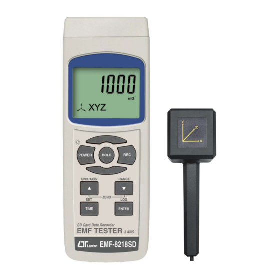
SD card real time datalogger, RS232/USB
EMF Strength Meter
Model : EMF-8218SD
Your purchase of this
Personal EMF
Strength Meter
with SD CARD
DATALOGGER marks a
step forward for you
into the field of
precision measurement.
Although this METER is
a complex and delicate
instrument, its durable
structure will allow
many years of use if
proper operating
techniques are
developed. Please read
the following
instructions carefully
and always keep this
manual within easy
reach.
OPERATION MANUAL
Advertisement
Table of Contents

Related Manuals for Lutron Electronics EMF-8218SD


Summary of Contents for Lutron Electronics EMF-8218SD
- Page 1 SD card real time datalogger, RS232/USB EMF Strength Meter Model : EMF-8218SD Your purchase of this Personal EMF Strength Meter with SD CARD DATALOGGER marks a step forward for you into the field of precision measurement. Although this METER is...
-
Page 2: Table Of Contents
TABLE OF CONTENTS 1. FEATURES..........................2. SPECIFICATIONS.......................... 3. FRONT PANEL DESCRIPTION..................... 4. MEASURING PROCEDURE....................4-1 EMF Strength Function selection and measurement.............. 4-2 Data Hold........................4-3 Data Record ( Max., Min. reading )..................5. DATALOGGER..........................5-1 Preparation before execute datalogger function..............5-2 Auto Datalogger ( Set sampling time ≧... -
Page 3: Features
1. FEATURES * Each axis (X, Y, Z direction )electromagnetic field measurement. * Sum of XYZ electromagnetic field measurement. * Range : 20/200/2000 micro Tesla. 200/2000/20000 milli-Gauss. * Measurement Bandwidth : 30Hz to 300Hz. * Non-directional (isotropic) measurement with three-channel (triaxial) measurement probe * Microcomputer circuit provides intelligent function and high accuracy. -
Page 4: Specifications
2. SPECIFICATIONS 2-1 General Specifications Circuit Custom one-chip of microprocessor LSI circuit. LCD size : 52 mm x 30 mm Display Measurement Digital, triaxial measurement. method Range Manual Datalogger Auto 2 to 3600 seconds Sampling Time Setting range Sampling time can set to 1 second, but memory data may loss. - Page 5 Over Indication Show " - - - - ". Data Hold Freeze the display reading. Memory Recall Maximum & Minimum value. Sampling Time Approx. 1 second. of Display Data Output RS 232/USB PC computer interface. Connect the optional RS232 cable UPCB-02 will get the RS232 plug.
- Page 6 2-2 Electrical Specifications (23±5 , 25% ~ 80 % RH) ℃ Frequency bandwidth 30Hz to 300Hz Units mGauss, µTesla. measurement range and 20μTesla (0.01) and 200mGauss (0.1) resolution: 200μTesla (0.1) and 2000mGauss (1) NOTE: 1 μTesla = 10 mGauss 2000μTesla (1) and 20,000mGauss (10) Accuracy ±...
-
Page 7: Front Panel Description
3. FRONT PANEL DESCRIPTION Fig. 1 3-1 Display. 3-2 Power Button 3-3 Hold Button 3-4 REC Button 3-5 ▲ Button (X,Y,Z,XYZ Function,UNIT Button) 3-6 ▼ Button ( RANG Button ) 3-7 Time Button (SET Button ) 3-15 Battery compartment/Cover 3-8 Enter Button ( Logger Button) 3-16 Tripod Fix Nut 3-9 SD card socket 3-17 EMF probe input. -
Page 8: Measuring Procedure
4. MEASURING PROCEDURE E-field sensors The tester meter that measures and displays EMF in Gauss and Tesla units with a frequency bandwidth of 30 to 300Hz. The 3 axis sensor allows for three component (xyz) measurement coverage. The tester Meter is specifically designed to determine the magnitude of electromagnetic fields generated by power lines, televisions, computers electric appliances and many other similar devices. -
Page 9: Data Hold
3. Pay special attention to measuring the neighboring vicinity for possible radiation sources. Apart from active sources, those components connected to a source may also act as radiators. For example, the cables used in diathermy equipment may also radiate electromagnetic energy. Note that metallic objects within the field may locally concentrate or amplify the field from a distant source. -
Page 10: Datalogger
5. DATALOGGER 5-1 Preparation before execute datalogger function a. Insert the SD card Prepare a " SD memory card " ( 1 G to 16 G, optional ), insert the SD card into the " SD card socket " ( 3-9, Fig. 1). The front panel of the SD card should face against the down case. -
Page 11: Auto Datalogger ( Set Sampling Time ≧ 1 Second )
5-2 Auto Datalogger ( Set sampling time 1 second ) ≧ a. Start the datalogger Press the " LOG Button ( 3-8, Fig. 1 ) > 1.5 seconds continuously, the LCD will show the text of " DATA LOGGER " indicator and flashing per second, at the same time the measuring data along the time information will be saved into the memory circuit. -
Page 12: Manual Datalogger ( Set Sampling Time = 0 Second )
5-3 Manual Datalogger ( Set sampling time = 0 second ) a. Set sampling time is to 0 second Press the " LOG Button ( 3-8, Fig. 1 )>1.5 second, the LCD will show the indicator " DATA LOGGER " and " Position no. " symbol then press the "... -
Page 13: Sd Card Data Structure
5-5 SD Card Data structure 1) When the SD card is used into the meter, the SD card When the first time, the SD card is used into the meter, the SD card will generate a folder : EMF01 2) If the first time to execute the Datalogger, under the route EMF01\, will generate a new file name EMF01001.XLS. -
Page 14: Saving Data From The Sd Card To The Computer
6. Saving data from the SD card to the computer ( EXCEL software ) 1) After execute the Data Logger function, take away the SD card out from the " SD card socket " ( 3-9, Fig. 1 ). 2) Plug in the SD card into the Computer's SD card slot ( if your computer build in this installation ) or insert the SD card into the "... - Page 15 EXCEL graphic screen (for example ) 1 2 3 4 5 6 7 8 9 10 11 12 13 14 15 16 17 18 19 20 21 22 23 24 25 26 27 28 29 30 31 32 33 XYZ_Value ChX_Value ChY_Value ChZ_Value...
-
Page 16: Advanced Setting
7. ADVANCED SETTING Under do not execute the Datalogger function, press the " SET Button " ( 3-7, Fig. 1 ) continuously at least 1.5 seconds will enter the " Advanced Setting " mode. then press the " SET Button " ( 3-7, Fig. 1 ) once a while display will show : SD-F.... -
Page 17: Set Clock Time ( Year/Month/Date,Hour/Minute/ Second )
7-2 Set clock time ( Year/Month/Date,Hour/Minute/ Second ) When the lcd display show " dAtE " 1) Press the " Enter Button " ( 3-8, Fig. 1 ) once, Use the " ▲ Button " ( 3-5, Fig. 1 ) or " ▼ Button " ( 3-6, Fig. -
Page 18: Auto Power Off Management
7-4 Auto power OFF management When the lcd display show " PoFF " 1) Use the " ▲ Button " ( 3-5, Fig. 1 ) or " ▼ Button " ( 3-6, Fig. 1 ) to select the lcd display show " YES " or "... -
Page 19: Decimal Point Of Sd Card Setting
7-6 Decimal point of SD card setting The numerical data structure of SD card is default used the " . " as the decimal, for example "20.6" "1000.53" . But in certain countries ( Europe ...) is used the " , " as the decimal point, for example "... -
Page 20: Power Supply From Dc Adapter
8. POWER SUPPLY from DC ADAPTER The meter also can supply the power supply from the DC 9V Power Adapter ( optional ). Insert the plug of Power Adapter into " DC 9V Power Adapter Input Socket " ( 3-12, Fig. 1 ). 9. - Page 21 Meter (9W 'D" Connector) Center Pin..........Pin 4 (3.5 mm jack plug) Ground/shield........... Pin 2 2.2 K resistor Pin 5 The 16 digits data stream will be displayed in the following format : D15 D14 D13 D12 D11 D10 D9 D8 D7 D6 D5 D4 D3 D2 D1 D0 Each digit indicates the following status : Start Word D12, D11...
-
Page 22: Patent
RS232 FORMAT : 9600, N, 8, 1 Baud rate 9600 Parity No parity Data bit no. 8 Data bits Stop bit 1 Stop bit 11. PATENT The meter ( SD card structure ) already get patent or patent pending in following countries : Germany Nr.
Need help?
Do you have a question about the EMF-8218SD and is the answer not in the manual?
Questions and answers