Table of Contents
Advertisement
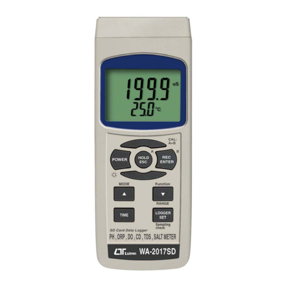
SD card real time datalogger
pH, ORP, CD, TDS, DO, SALT
METER
Model : WA-2017SD
OPERATION MANUAL
Your purchase of this
pH, ORP, CD, TDS, DO,
SALT METER with SD
CARD
DATALOGGER
marks a step forward for
you into the field of
precision measurement.
A l t h o u g h
DATALOGGER
complex
and
instrument, its durable
structure
will
many years of use if
p r o p e r
o p e r a t i n g
t e c h n i q u e s
developed. Please read
t h e
f o l l o w i n g
instructions
and always keep this
manual
within
reach.
t h i s
is
a
delicate
allow
a r e
carefully
easy
Advertisement
Table of Contents

Related Manuals for Lutron Electronics WA-2017SD


Summary of Contents for Lutron Electronics WA-2017SD
- Page 1 SD card real time datalogger pH, ORP, CD, TDS, DO, SALT METER Model : WA-2017SD Your purchase of this pH, ORP, CD, TDS, DO, SALT METER with SD CARD DATALOGGER marks a step forward for you into the field of precision measurement.
-
Page 2: Table Of Contents
TABLE OF CONTENTS 1. FEATURES..............1 2. SPECIFICATIONS............3 2-1 General Specifications..........3 2-2 Electrical Specifications......... 3. FRONT PANEL DESCRIPTION.........10 4. MODE SELECTION............12 5. PH/mV MEASURING and CALIBRATION PROCEDURE..............13 6. CONDUCTIVITY/TDS MEASURING and CALIBRATION PROCEDURE...........19 7. SALT MEASURING and calibration PROCEDURE....23 8. -
Page 3: Features
1. FEATURES * One meter for multi purpose operation : PH/ORP, CD/TDS, Dissolved Oxygen, Salt measurement. * pH : 0 to 14.00 pH, ORP : ± 1999 mV. * Conductivity : 200 uS/2 mS/20 mS/200 mS. * Dissolved oxygen : 0 to 20.0 mg/L. * Salt : 0 to 12 % salt ( % weight ). - Page 4 * Wide applications: water conditioning, aquariums, beverage, fish hatcheries, food processing, photography, laboratory, paper industry, plating industry, quality control, school & college, water conditioning. * Real time SD memory card Datalogger, it Built-in Clock and Calendar, real time data recorder , sampling time set from 1 sec to 8 hour 59 min.
-
Page 5: Specifications
2. SPECIFICATIONS 2-1 General Specifications Circuit Custom one-chip of microprocessor LSI circuit. Display LCD size : 52 mm x 38 mm LCD with green backlight ( ON/OFF ). Measurement PH/ORP Function Conductivity/TDS(Total Dissolved Solids) Dissolved Oxygen Salt Datalogger Auto 1 sec to 8 hour 59 min. 59 sec. Sampling Time @ Sampling time can set to 1 second, Setting range... - Page 6 Sampling Time Approx. 1 second. of Display Data Output RS 232/USB PC computer interface. * Connect the optional RS232 cable UPCB-02 will get the RS232 plug. * Connect the optional USB cable USB-01 will get the USB plug. Operating 0 to 50 ℃...
-
Page 7: Electrical Specifications
Optional * PH electrode....... Accessories PE-03, PE-11, PE-01, PE06HD PE-04HD, PE-05T, PE-03K7 * ATC probe ( Automatic Temperature Probe )........TP-07 * pH 7 buffer solution....PH-07 * pH 4 buffer solution....PH-04 * Conductivity/TDS probe, Salt probe......CDPB-03 * 1.413 mS Conductivity Standard Solution........ - Page 8 Temperature Manual 0 to 100 , be adjusted by ℃ Compensation push button on front panel. for pH Automatic With the optional temperature measurement ( ATC ) probe ( TP-07 ) 0 to 65 ℃ PH7, PH4, and PH10, 3 points calibration Calibration ensure the best linearity and accuracy.
- Page 9 1. Conductivity ( uS, mS ) Range Measurement Resolution Accuracy 200 uS 0 to 200.0 uS 0.1 uS 2 mS 0.2 to 2.000 mS 0.001 mS ± (2% F.S.+1d) 20 mS 2 to 20.00 mS 0.01 mS * F.S. - 200 mS 20 to 200.0 mS 0.1 mS...
- Page 10 C. Salt Conductivity Optional, probe Carbon rod electrode for long life. Measurement 0 to 12 % salt ( % weight ). Range Resolution 0.01 % salt. Accuracy 0.5 % salt value * F.S. : full scale. Temperature Automatic from 0 to 60 (32 - 140 ℃...
- Page 11 D. Dissolved oxygen Oxygen Optional, Probe The polarographic type oxygen probe with Measurement Dissolved Oxygen 0 to 20.0 mg/L ( liter ). & Range Oxygen in Air 0 to 100.0 %. Temperature 0 to 50 ℃ Resolution Dissolved Oxygen 0.1 mg/L. Oxygen in Air 0.1 % O2 .
-
Page 12: Front Panel Description
3. FRONT PANEL DESCRIPTION... - Page 13 3-1 Display 3-2 Power Button ( Backlight Button ) 3-3 Hold Button ( ESC Button ) 3-4 REC Button ( Enter Button ) 3-5 Mode Button ( Button ) ▲ 3-6 Range Button ( Button, Function Button ) ▼ 3-7 Time Button 3-8 Logger Button ( SET Button, Sampling check ) 3-9 Stand 3-10 Battery Compartment/Cover...
-
Page 14: Mode Selection
4. MODE SELECTION 1) Turn on the meter by pressing the " Power Button " ( 3-2, Fig. 1 ) momentarily. Pressing the " Power Button " ( 3-2, Fig. 1 ) continuously and > 2 seconds again will turn off the meter. -
Page 15: Ph/Mv Measuring And Calibration Procedure
5. PH/mV MEASURING and CALIBRATION PROCEDURE The meter default function are following : * The display unit is set to pH. * The temperature unit is set to ℃ * Manual ATC ( without connect the ATC probe ) * Auto power off. * The sampling time of data logger function is 2 seconds. - Page 16 5-1 pH measurement ( manual Temp. compensation ) 1) Power on the meter by pressing " Power Button " ( 3-2, Fig. 1 ) once. Select the Meter's measurement Mode to " PH ", refer to Chapter 4, page 12. 2) Prepare the pH Electrode ( optional ), install the "...
- Page 17 When not use the Electrode, it should immerse the " Electrode sensing head " ( 5-3, Fig. 2 ) into the " Protection bottle " ( 5-4, Fig. 2 ) 5-3 mV Measurement The instrument build in mV ( millivolt ) measurement function, which enable you to make ion-selective, ORP (oxidation-reduction potential), and other precise mV measurements.
- Page 18 Required Equipment for Calibration 1) pH ELECTRODE ( optional ). 2) pH buffer solutions ( optional ). Calibration Procedure 1) Prepare the pH Electrode ( optional ), install the " Probe Plug " ( 5-1, Fig. 2 ) into the " PH Socket/BNC Socket "...
- Page 19 5) Use the two fingers to press the " REC Button " ( 3-4, Fig 1 ) and " HOLD Button " ( 3-3, Fig. 1 ) at the same time. Until Display will show the following screen then release the both fingers. 6) Press the "...
- Page 20 * After the above a, b, c screen is selected, then cooperate the relative standard solution, for example the b screen should cooperate the pH 7.00 standard solution. a screen should cooperate the pH 4.00 standard solution. Press the " Enter Button " ( 3-4, Fig. 1 ) will save the calibration data and finish the calibration procedures.
-
Page 21: Conductivity/Tds Measuring And Calibration Procedure
6. CONDUCTIVITY/TDS MEASURING and CALIBRATION PROCEDURE The meter default function are following : * The display unit is set to conductivity ( uS, mS ). * The temperature unit is set to ℃ * Temp. compensation factor is set to 2.0% per C. * Auto range. - Page 22 6-1 Conductivity measurement 1) Prepare the Conductivity Probe ( included, CDPB-03 ), install the " Probe Plug " ( 6-1, Fig. 3 ) into the " CD Socket " ( 3-15, Fig. 1 ). 2) Power on the meter by pressing " Power Button " ( 3-2, Fig.
- Page 23 Change the Temp. Coefficient Factor The default Temp. compensation factor value of the measurement solution is to 2.0% per . If intend to ℃ change it, please refer to chapter 12-11, page 45. Zero adjustment If the probe not immerse the measurement solution and display not show zero value, pressing the "...
- Page 24 2) Install the " Probe Plug " ( 6-1, Fig. 3 ) into the " CD Socket " ( 3-15, Fig. 1 ). 3) Power on the meter by pressing " Power Button " ( 3-2, Fig. 1 ) once. Select the Meter's measurement Mode to "...
-
Page 25: Salt Measuring And Calibration Procedure
Standard value 1.318 1.413 1.318 1.318 * If only intend to make the one point calibration, just execute the 2 mS range ( 1.413 mS Cal. ) is enough. * Multi-points calibration procedures should execute the 2 mS range ( 1.413 mS Cal. ) calibration at first, then make other ranges (20 uS range, 20 mS range or 200 mS range ) calibration procedures following if necessary. - Page 26 7-1 Salt measurement 1) Prepare the Conductivity Probe ( included, CDPB-03 ), install the " Probe Plug " ( 7-1, Fig. 4 ) into the " CD Socket " ( 3-15, Fig. 1 ). 2) Power on the meter by pressing " Power Button " ( 3-2, Fig.
-
Page 27: Do ( Dissolved Oxygen ) Measuring And Calibration Procedure
8. DO ( Dissolved Oxygen ) MEASURING and CALIBRATION PROCEDURE 8-1 Dissolved Oxygen measurement Fig. 5 1) Prepare the Oxygen Probe ( optional, DOPB-11 ), install the " Probe Plug " ( 8-1, Fig. 5 ) into the " DO Socket " ( 3-14, Fig. 1 ). 2) Power on the meter by pressing "... - Page 28 Calibration at first ! If it is the first time to use the Dissolved Oxygen meter or after a certain period to use the meter again, then it should to execute the calibration procedures at the first. For the measurement precisely consideration, it recommend to make the calibration before each measurement.
- Page 29 6) Display will show the Dissolved Oxygen values ( mg/L ) at the same time the bottom display will show the Temp. value of the measured solution. 7) Rinsed the probe accurately with normal tap water after each series of measurement. Oxygen in the air During the DO measurement, press the "...
- Page 30 8-2 Calibration 1) Install the " Probe Plug " ( 8-1, Fig. 5 ) into the " DO Socket " ( 3-14, Fig. 1 ). 2) Power on the meter by pressing " Power Button " ( 3-2, Fig. 1 ) once. * Select the Meter's mode to "...
- Page 31 9-3. Probe maintenance User first time to use the meter Intend to let the DO probe keep the best condition, when user receive the Oxygen Probe, it should fill the Probe's Electrolyte at first. User already use the probe for a certain period : Whenever user can not calibrate the meter properly or the meter's reading value is not stable,...
- Page 32 Probe-filling Electrolyte, OXEL-03 1) Unscrew the " Probe head " ( 9-3, Fig 6 ). 2) Pour out the old Electrolyte from the container of the " Probe head ". 3) Fill the new Electrolyte ( OXEL-03 ) into the container of the " Probe head "...
-
Page 33: Other Function
9. OTHER FUNCTION 9-1 Data Hold During the measurement, press the " Hold Button " ( 3-3, Fig. 1 ) once will hold the measured value & the LCD will display a " HOLD " symbol. Press the " Hold Button " once again will release the data hold function. -
Page 34: Lcd Backlight On/Off
9-3 LCD Backlight ON/OFF After power ON, the " LCD Backlight " will light automatically. During the measurement, press the " Backlight Button " ( 3-2, Fig. 1 ) once will turn OFF the " LCD Backlight ". Press the " Backlight Button " once again will turn ON the "... -
Page 35: Auto Datalogger ( Set Sampling Time ≧ 1 Second )
10-2 Auto Datalogger ( Set sampling time 1 second ) ≧ a. Start the datalogger Press the " REC Button ( 3-4, Fig. 1 ) once , the LCD will show the text " REC ", then press the " Logger Button " ( 3-8, Fig. -
Page 36: Manual Datalogger ( Set Sampling Time = 0 Second )
10-3 Manual Datalogger ( Set sampling time = 0 second ) a. Set sampling time is to 0 second Press the " REC Button ( 3-4, Fig. 1 ) once , the LCD will show the text " REC ", then press the " Logger Button " ( 3-8, Fig. -
Page 37: Check Time Information
10-4 To check the time information During the normal measurement screen ( not execute the Datalogger ), 1) If press " Time Button " ( 3-7, Fig. 1 ) once , the lower LCD display will present the time information of Hour/Minute/Second ( h.m.s ) in the lower Display. - Page 38 2) If the first time to execute the Datalogger, under the route WAA01\, will generate a new file name WAA01001.XLS. After exist the Datalogger, then execute again, the data will save to the WAA01001.XLS until Data column reach to 30,000 columns, then will generate a new file, for example WAA01002.XLS 3) Under the folder WAA01\, if the total files more than 99 files, will generate anew route, such as...
-
Page 39: Saving Data From The Sd Card To The Computer
11. Saving data from the SD card to the computer ( EXCEL software ) 1) After execute the Data Logger function, take away the SD card out from the " SD card socket " ( 3-20, Fig. 1 ). 2) Plug in the SD card into the Computer's SD card slot ( if your computer build in this installation ) or insert the SD card into the "... - Page 40 EXCEL data screen ( for example 2) EXCEL data screen ( for example 3)
-
Page 41: Advanced Setting
12. ADVANCED SETTING Under do not execute the Datalogger function, press the " SET Button " ( 3-8, Fig. 1 ) continuously at least two seconds will enter the " Advanced Setting " mode. then press the " SET Button " ( 3-8, Fig. 1 ) once a while in sequence to select the eight main function, the display will show : Sd F.. - Page 42 12-1 SD memory card Format When the lower display show " Sd F " 1) Use the " Button " ( 3-5, Fig. 1 ) or " Button " ( ▲ ▼ 3-6, Fig. 1 ) to select the upper value to " yES " or "...
- Page 43 2) After set all the time value ( Year, Month, Date, Hour, Minute, Second ), press the " SET Button " ( 3-8, Fig. 1 ) once will save the time value, then the screen will jump to Sampling time " setting screen ( Chapter 12-3 ). Remark : After the time value is setting, the internal clock will run precisely even Power off if the battery is under...
- Page 44 12-4 Auto power OFF management When the lower display show " PoFF " 1) Use the " Button " ( 3-5, Fig. 1 ) or " Button " ▲ ▼ ( 3-6, Fig. 1 ) to select the upper value to " yES " or "...
- Page 45 12-6 Decimal point of SD card setting The numerical data structure of SD card is default used the " . " as the decimal, for example "20.6" "1000.53" . But in certain countries ( Europe ...) is used the " , " as the decimal point, for example "...
- Page 46 2) After Display unit is selected to " C " or " F ", press the " Enter Button " ( 3-4, Fig. 1 ) will save the setting function with default. 12-8 Set DO salt% compensation value When the lower display show " SALt " 1) This function only for the DO ( Disolved oxygen ) mode of adjusting the probe's salt% compensation value.
- Page 47 12-10 Set DO height ( feet ) compensation value When the lower display show " Highf " 1) This function only for the DO ( Disolved oxygen ) mode of adjusting the probe's height compensation value in feet unit. The default value is 0 FEET. 2) Use the "...
- Page 48 tdS - TDS ( PPM ) Cd - Conductivity ( uS, mS ) 2) Use the " Button " ( 3-5, Fig. 1 ) or " Button " ▲ ▼ ( 3-6, Fig. 1 ) to select the upper text to " Cd " or " tdS ". then press the "...
-
Page 49: Power Supply From Dc Adapter
13. POWER SUPPLY from DC ADAPTER The meter also can supply the power supply from the DC 9V Power Adapter ( optional ). Insert the plug of Power Adapter into " DC 9V Power Adapter Input Socket " ( 3-17, Fig. 1 ). The meter will permanent power ON when use the DC ADAPTER power supply ( The power Button function is disable ). -
Page 50: Rs232 Pc Serial Interface
16. RS232 PC SERIAL INTERFACE The instrument has RS232 PC serial interface via a 3.5 mm terminal ( 3-19, Fig. 1 ). The data output is a 16 digit stream which can be utilized for user's specific application. A RS232 lead with the following connection will be required to link the instrument with the PC serial port. -
Page 51: Optional Accessories
D12, D11 Annunciator for Display uS = 13 mS = 14 PPM = 19 PH = 05 mV = 18 % = 03 mg/L = 07 % O2 = 06 Polarity 0 = Positive 1 = Negative Decimal Point(DP), position from right to the left 0 = No DP, 1= 1 DP, 2 = 2 DP, 3 = 3 DP D8 to D1... - Page 52 Data * The SW-U801-WIN is a multi Acquisition displays ( 1/2/4/6/8 displays ) software powerful application software, SW-U801-WIN provides the functions of data logging system, text display, angular display, chart display, data recorder high/low limit, data query, text report, chart report.. .xxx.mdb data file can be retrieved for EXCEL, ACESS.., wide intelligent applications.
-
Page 53: Patent
Conductivity * Conductivity/Salt probe Salt Model : CDPB-03 optional * 1.413 mS standard solution. accessories Model : CD-14 Dissolved * Oxygen probe Oxygen Model : OXPB-11 optional * Spare Probe head with Diaphragm set accessories Model : OXHD-04 * Probe-filling Electrolyte Model : OXEL-03 * ORP electrode Model : ORP-14...
Need help?
Do you have a question about the WA-2017SD and is the answer not in the manual?
Questions and answers