Table of Contents
Advertisement
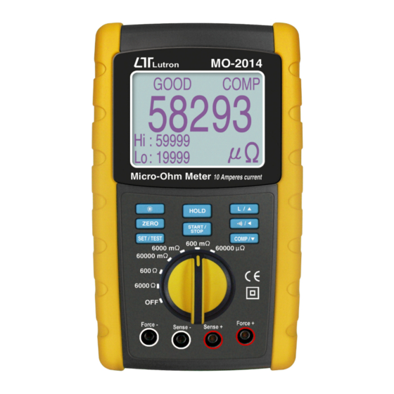
10 Amperes max. test current
Micro-Ohm Meter
Model : MO-2014
OPERATION MANUAL
Your
purchase
this
Micro-Ohm
METER
marks
step
forward
you into the field of
p r e c i s i o n
measurement.
A l t h o u g h
Micro-Ohm
METER
is a complex and
delicate instrument,
its durable structure
will
allow
years
of
use
proper
operating
techniques
developed.
Please
read the following
i n s t r u c t i o n s
carefully and always
keep this manual
within easy reach.
of
a
for
t h i s
many
if
are
Advertisement
Table of Contents

Related Manuals for Lutron Electronics MO-2014


Summary of Contents for Lutron Electronics MO-2014
- Page 1 10 Amperes max. test current Micro-Ohm Meter Model : MO-2014 Your purchase this Micro-Ohm METER marks step forward you into the field of p r e c i s i o n measurement. A l t h o u g h...
-
Page 2: Table Of Contents
TABLE OF CONTENTS 1. FEATURES...............1 2. SPECIFICATIONS............. 1 2-1 General Specifications.........1 2-2 Electrical Specifications........2 3. FRONT / REAR PANEL DESCRIPTION......3 4. BASIC 4 WIRES MEASURING PRINCIPLE....4 5. PRECAUTION & PREPARATIONS FOR MEASUREMENT............5 6. MEASURING PROCEDURES........5 6-1 Buttons instructions ........5 6-2 Symbols &... -
Page 3: Features
1. FEATURES * 4 terminal devices for accurate measurement of very low resistance. * Ideal for measuring the resistance of components precisely. * Ideal for testing protective conductors, lightning conductors and welded points. * Maximum test current is 10A ( 60000 uΩ range only ). * Have two working mode , Resistive and Inductive mode, Normal is resistive mode. -
Page 4: Electrical Specifications
Fuse protect * 10 A / 250 V * Size : 6.3 X 32 mm dia.. Dimension 225 x 125 x 64 mm ( 8.86 x 4.92 x 2.52 inch) Weight Approx. 790 g ( 1.74 LB ). Standard 4 wire with 2 Kelvin clips..1 pair Accessories Instruction Manual....1 PC 1 set... -
Page 5: Front/Rear Panel Description
3. FRONT/REAR PANEL DESCRIPTION Fig. 1 3-1 Display 3-11 Force Terminal "+" 3-2 Backlight key button 3-12 Sense Terminal "+" 3-3 Zero key button 3-13 Sense Terminal "-" 3-4 SET / TEST key button 3-14 Force Terminal "-" 3-5 HOLD key button 3-15 RS232 socket 3-6 START / STOP key button 3-16 Reset button... -
Page 6: Basic 4 Wires Measuring Principle
4. BASIC 4 WIRES MEASURING PRINCIPLE The DIGITAL MICRO-OHM METER is a precise, wide range, small resistance and high resolution measuring instrument. As for preventing any measuring errors, especially to avoid the influence of "LEAD STRAY RESISTANCE" or "TEST WIRE'S RESISTANCE", the meter is designed according to the following "4 WIRES MEASURING PRINCIPAL"... -
Page 7: Precaution & Preparations For Measurement
5. PRECAUTION & PREPARATIONS FOR MEASUREMENT * Please check carefully the meter's power supply is DC 9V power adapter before operating at 60000 uΩ range . * It's prohibited to input voltage to the 4 wire input terminal ( Force +, Sense +, Sense -, Force - ) to prevent any internal circuit damage. -
Page 8: Symbols & Units Of Display
6 -2 Symbols & units of display Function Symbol & Unit Ohm unit uΩ ,mΩ ,Ω Appears on the "BEEP" function have .))) started. HOLD Appears on the"HOLD" function have started. It is pass Q.C. Appears on finished GOOD compare operate. It is higher or lower than maximum or FAIL minimum acceptance value . -
Page 9: Hi/Lo Warning Setup
2) Connect the * Red cable ( with white O ring marker ) to " Force + " terminal ( 3-11, Fig. 1 ) * Red cable ( no white O ring marker ) to " Sense + " terminal ( 3-12, Fig. 1 ) * Black cable ( with white O ring marker ) to "... - Page 10 press the " BEEP / " buttons (3-8 , Fig. 1) set warning value , When user to move 1st digit unit to next digit unit (10th, 100th. 1000th). * Hypothesize display be set at 180.00 . 2) LO warning value setup Finished (1) procedure then press the "...
-
Page 11: Calculate Cable/Wire Length
8. CALCULATE CABLE/WIRE LENGTH Before calculate cable length . You should sampling one unit length (meter or feet). 1) Primary to take one sample from a lot of cable or wire then to to measure 1 m or 1 feet length - unit. 2) Measue the unknown cable . -
Page 12: Rs232 Pc Serial Interface
9. RS232 PC SERIAL INTERFACE The instrument has RS232 PC serial interface via a 3.5 mm terminal ( 3-15, Fig. 1 ). The data output is a 16 digit stream which can be utilized for user's specific application. A RS232 lead with the following connection will be required to link the instrument with the PC serial port. -
Page 13: Battery Replacement
D12, D11 Annunciator for Display Ω = 38 mΩ = B1 uΩ = F5 Polarity 0 = Positive 1 = Negative Decimal Point(DP), position from right to the left 0 = No DP, 1= 1 DP, 2 = 2 DP, 3 = 3 DP D8 to D1 Display reading, D1 = LSD, D8 = MSD For example :...
Need help?
Do you have a question about the MO-2014 and is the answer not in the manual?
Questions and answers