Table of Contents
Advertisement
Quick Links
50 MHz to 3 GHz Radio Frequency Radiation Meters
Electromagnetic Field strength measurement
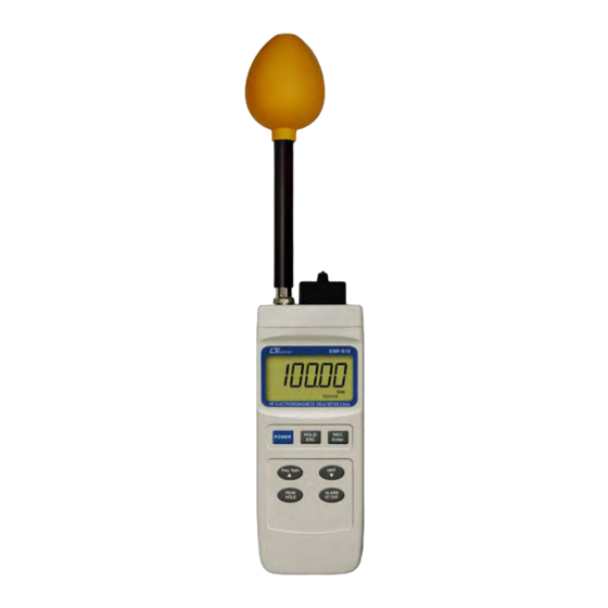
3 AXIS RF ELECTROMAGNETIC
FIELD METER
Model : EMF-819
OPERATION MANUAL
Your purchase of this RF
EMF METER marks a
step forward for you
into
the
field
precision measurement.
Although this METER is
a complex and delicate
instrument, its durable
structure
will
many years of use if
p r o p e r
o p e r a t i n g
t e c h n i q u e s
developed. Please read
t h e
f o l l o w i n g
instructions
and always keep this
manual
within
reach.
of
allow
a r e
carefully
easy
Advertisement
Table of Contents

Related Manuals for Lutron Electronics EMF-819


Summary of Contents for Lutron Electronics EMF-819
- Page 1 50 MHz to 3 GHz Radio Frequency Radiation Meters Electromagnetic Field strength measurement 3 AXIS RF ELECTROMAGNETIC FIELD METER Model : EMF-819 Your purchase of this RF EMF METER marks a step forward for you into field precision measurement. Although this METER is...
-
Page 2: Table Of Contents
TABLE OF CONTENTS 1. FEATURES..............1 2. APPLICATIONS............2 3. SAFETY INSTRUCTIONS..........2 4. SPECIFICATIONS............4 5. FRONT PANEL DESCRIPTION........6 6. MEASUREMENT CONSIDERATION.........7 7. MEASURING PROCEDURE..........8 7-1 Buttons instructions..........8 7-2 Symbols & units of display........9 7-3 Unit Selection............10 7-4 Frequency Team Selection........10 7-5 Alarm Limit Setting and Alarm start...... -
Page 3: Features
* 3 Axis probe. * Radio frequency electromagnetic field tester. * Wide measuring frequency ranges, 50 MHz to 3 GHz. * EMF-819 is used for broadband devices of monitoring the wide range radio frequency electromagnetic field value. * For precision measurement consideration, the meter... -
Page 4: Applications
2. APPLICATIONS This meter is specially developed for measuring or monitoring electromagnetic field, for example: cell-phone station, hospital equipment, radar , micro-wave oven, radiation work, TV antenna , Radio station , welding equipment , baking- equipment, television , computer , factory, laboratory , and other environment...etc. - Page 5 * Complete answers to any of these and related " Prudent Avoidance " as stated by the Environmental Protection Agency(EPA) USA is recommended. * According to ICNIRP of reference levels to time-varying electromagnetic fields. The E-field strength levels are: General public Frequency range e-field strength (V/m) 10 to 400 MHz...
-
Page 6: Specifications
4. SPECIFICATIONS 4-1 General Specifications Circuit Custom one-chip of microprocessor LSI circuit. Display LCD size : 58 mm x 34 mm. Measurement V/m, mW/cm^2, W/m^2. Unit Accuracy < 2 dB. Probe structure 3 Axis. Probe Input 50 OHM Impedance Frequency Two points selection : Normal, 2.45 GHz. - Page 7 Power Supply DC 9 V battery ( 006P ) * Heavy duty or Alkaline type. DC 9V adapter input. Power Current Approx. DC 5.95 mA Weight 425 g/ 0.94 LB. Main instrument : Dimension 200.0 x 76.2 x 36.8 mm Probe : 70 mm ( diameter) x 240 mm ( length) Accessories...
-
Page 8: Front Panel Description
5. FRONT PANEL DESCRIPTION Fig. 1 5-1 Display 5-10 Probe Memory Card 5-2 Power Button 5-11 DC Adapter Input Socket 5-3 Hold / ESC Button 5-12 RS-232 Output Terminal 5-4 REC / Enter Button 5-13 LCD contrast adj. 5-5 Freq. Team Button 5-14 Battery Cover 5-6 Unit Button 5-15 Stand... -
Page 9: Measurement Consideration
6. MEASUREMENT CONSIDERATION 1) Connect the " Probe Plug " ( 5-18, Fig. 1 ) into the " Probe Input Socket " ( 5-9, Fig. 1 ). 2) Plug in the exclusive " Probe Memory Card " ( 5-10, Fig. 1 ) into the front end socket of meter. -
Page 10: Measuring Procedure
3) The meter is build in the 3 axis ( X, Y, Z ) EMF sensors, the circuit measure each X, Y, Z sensor's EMF value, then the CPU will calculate the total EMF value according the following formula : X : The EMF value that sensing from the X direction. -
Page 11: Symbols & Units Of Display
7 -2 Symbols & units of display Symbol & Function Unit Electric field strength W/m^2 Power density mW/cm^2 Power density Normal, Frequency team indicates. 2.45 GHz PEAK HOLD Appears on the " PEAK HOLD " function. It will latch the peak value. Appears on the "... -
Page 12: Unit Selection
7-3 Unit Selection After inserting the " Probe Memory Card " ( 5-10, Fig. 1 ) and connecting " Probe Plug " ( 5-18, Fig. 1 ) into the " Probe Input Socket " ( 5-9, Fig. 1 ), use " Unit Button " ( 5-6, Fig. 1) to select the "... -
Page 13: Data Hold
5) After finish the " High limit value " adjustment, press the " Enter Button " ( 5-4, Fig. 1 ) will save the high limit value and going to adjust the alarm Hysteresis value, procedures will similar as above. Upon finish the alarm "... -
Page 14: Peak Hold
7-8 Peak Hold Press the " Peak Hold Button " ( 5-7, Fig. 1 ) once to latch peak value on the display , press once again to exit the peak hold function. 8. AUTO POWER OFF DISABLE The instrument has built-in "Auto Power Shut-off" in order to prolong battery life. - Page 15 The 16 digits data stream will be displayed in the following format : D15 D14 D13 D12 D11 D10 D9 D8 D7 D6 D5 D4 D3 D2 D1 D0 Each digit indicates the following status : End Word = 0D D1 &...
-
Page 16: Battery Replacement
10. BATTERY REPLACEMENT When the left corner of LCD display show " ", it is necessary to replace the batteries ( 006P ). 1) Slide the " Battery Cover " ( 5-14, Fig. 1 ) away from the instrument and remove the battery. 2) Replace with batteries ( 006P ) and reinstate the cover. -
Page 17: Optional Accessories
12. OPTIONAL ACCESSORIES RS232 cable * Computer interface cable. UPCB-02 * Used to connect the meter to the computer ( COM port ). USB cable * Computer interface cable. USB-01 * Used to connect the meter to the computer ( USB port ). Data Acquisition * The SW-U801-WIN is a multi software...
Need help?
Do you have a question about the EMF-819 and is the answer not in the manual?
Questions and answers