Table of Contents
Advertisement
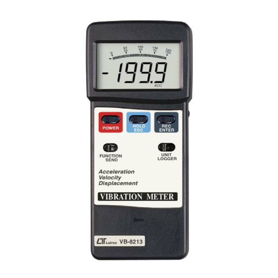
Acceleration/Velocity/Displacement
RMS/Peak/Max. Hold, Metric & Imperial unit
VIBRATION METER
Model : VB-8213
OPERATION MANUAL
Your purchase of this
VIBRATION
marks a step forward for
you into the field of
precision measurement.
Although this METER is
a complex and delicate
instrument, its durable
structure
will
many years of use if
p r o p e r
o p e r a t i n g
t e c h n i q u e s
developed. Please read
t h e
f o l l o w i n g
instructions
and always keep this
manual
within
reach.
METER
allow
a r e
carefully
easy
Advertisement
Table of Contents

Related Manuals for Lutron Electronics VB-8213


Summary of Contents for Lutron Electronics VB-8213
- Page 1 Acceleration/Velocity/Displacement RMS/Peak/Max. Hold, Metric & Imperial unit VIBRATION METER Model : VB-8213 Your purchase of this VIBRATION METER marks a step forward for you into the field of precision measurement. Although this METER is a complex and delicate instrument, its durable...
-
Page 2: Table Of Contents
TABLE OF CONTENTS 1 FEATURES..............1 2 SPECIFICATIONS............2 2-1 General Specifications.......... 2 2-2 Electrical Specifications........4 3 FRONT PANEL DESCRIPTION........7 3-1 Display..............8 3-2 Power Button............8 3-3 Hold/ESC Button ..........8 3-4 REC/ENTER Button ..........8 3-5 FUNCTION/SEND Button........8 3-6 UNIT/LOGGER Button.......... 8 3-7 Battery Cover/Compartment......... -
Page 3: Features
1. FEATURES * Applications for industrial vibration monitoring : All industrial machinery vibrates. The level of vibration is a useful guide to machine condition. Poor balance, misalignment & looseness of the structure will cause the vibration level increase, it is a sure sign that the maintenance is needed. -
Page 4: Specifications
2. SPECIFICATIONS 2-1 General Specifications Display 52 mm x 38 mm, LCD display. 16 mm ( 0.63" ) digit size. With bar graph indicator. Measurement Velocity, Acceleration, Displacement Main Function RMS, Peak, Max. Hold. Others Data hold, Max. & Min. value, Data logger. - Page 5 Data output RS 232 serial output, isolate. Operating 0 to 50 ( 32 to 122 ℃ ℉ temperature Operating Less than 80% RH. humidity Power supply Alkaline or heavy duty type, DC 9V battery, 006P, MN1604 (PP3) or equivalent. Power Approx.
-
Page 6: Electrical Specifications
2-2 Electrical Specifications Acceleration ( RMS, Peak, Max Hold ) Unit Range 0.5 to 199.9 Resolution Accuracy ± ( 5 % + 2 d ) reading @ 160 Hz, 80 Hz, 23 ± 5 ℃ Calibration ( 160 Hz ) Point @ 1 G = 9.8 Unit... - Page 7 Velocity ( RMS, Peak, Max Hold ) Unit mm/s Range 0.5 to 199.9 mm/s Resolution 0. 1 mm/s Accuracy ± ( 5 % + 2 d ) reading @ 160 Hz, 80 Hz, 23 ± 5 ℃ Calibration 50 mm/s ( 160 Hz ) Point Unit cm/s...
- Page 8 Displacement p-p ( RMS, Max Hold ) Unit Range 1.999 mm Resolution 0.001 mm Accuracy ± ( 5 % + 2 d ) reading @ 160 Hz, 80 Hz, 23 ± 5 ℃ Calibration 0.141 mm ( 160 Hz ) Point Unit inch...
-
Page 9: Front Panel Description
3. FRONT PANEL & LAYOUT DESCRIPTION Fig. 1... -
Page 10: Display
Fig. 2 3-1 Display 3-2 Power Button 3-3 Hold/ESC Button 3-4 REC/ENTER Button 3-5 FUNCTION/SEND Button 3-6 UNIT/LOGGER Button 3-7 Battery Cover/Compartment 3-8 RS232 Output terminal 3-9 BNC socket of meter 3-10 BNC plug of cable 3-11 Mini plug of cable 3-12 Input socket of vibration sensor 3-13 Vibration sensor 3-14 Magnetic base... -
Page 11: Measuring Procedure
4. MEASURING PROCEDURE 1)Plug in the " BNC plug of cable " ( 3-10, Fig. 2 ) to the " BNC socket of meter " ( 3-9, Fig. 1 ). 2)Plug in the " Mini plug of cable " ( 3-11, Fig. 2 ) to the "... - Page 12 5)UNIT SELECTION : Select the desired display unit by pressing the " UNIT Button " ( 3-6, Fig. 1 ). The unit can be selected as : Measurement Metric unit Imperial unit Acceleration Velocity mm/s, cm/s inch/s Displacement inch Remarks : For general applications of industrial vibration monitoring, select "...
-
Page 13: Zero Adjustment Procedure
7)Data Record ( Max., Min. reading ) The DATA RECORD function displays the maximum, and minimum readings. a. Get into RECORD mode by momentarily pressing " REC Button " ( 3-4, Fig. 1 ) once. REC icon will be ON. b. -
Page 14: Power Management
4)Set the function and the unit to " ACC, RMS " . 5)Keep the vibration sensor motionless, no signal into the vibration sensor. 6)Press the " HOLD Button " ( 3-3, Fig. 1 ) continuously at least 2 seconds will let the display reach zero value. - Page 15 Auto data logger If the data sampling time already set to 1, 2, 10, 30, 60, 600, 1800 or 3600 second, then the meter can be executed the auto data logger function. The procedures that to set the data logger sampling time, please refer page 14.
- Page 16 Manual data logger If the data sampling time already set to 0 second, then the meter can be executed the manual data logger function. The procedures that to set the data logger sampling time, please refer page 14. 1. Press the " REC Button " ( 3-4, Fig. 1 ) once to start the Data Record function and there will be a "...
- Page 17 3. Press the " UNIT Button " ( 3-6, Fig. 1 ) once a while will change the sampling time ( 1, 2, 5, 10, 30, 60, 600, 1800, 3600 seconds ). After the desired sampling be selected, then press the " REC Button " ( 3-4, Fig. 1 ) to save.
-
Page 18: How To Send The Data Out From The Meter
3. Press the " HOLD Button " ( 3-3, Fig, 1 ) or the FUNCTION Button " ( 3-5, Fig. 1 ) will search the the data that already save into the memory. * " HOLD Button " - Increase the data no. * "... -
Page 19: Rs232 Pc Serial Interface
9. RS232 PC SERIAL INTERFACE The instrument has RS232 PC serial interface via a 3.5 mm terminal ( 3-8, Fig. 2 ). The data output is a 16 digit stream which can be utilized for user's specific application. A RS232 lead with the following connection will be required to link the instrument with the PC serial port. - Page 20 Each digit indicates the following status : End Word D1 & D8 Display reading, D1 = LSD, D8 = MSD For example : If the display reading is 1234, then D8 to D1 is : 00001234 Decimal Point(DP), position from right to the left 0 = No DP, 1= 1 DP, 2 = 2 DP, 3 = 3 DP Polarity...
-
Page 21: Battery Replacement
10. BATTERY REPLACEMENT 1)When the left up corner of LCD show " " indicator, it is necessary to replace the battery. However, in-spec measurement may still be made for several hours after low battery indicator appears before the instrument become inaccurate. 2)Open the "... -
Page 22: Classification Ranges
12. CLASSIFICATION RANGES For the valuation of machines and equipment in the ISO 2372 and VDI 2056, four different kinds of machine groups with four classification ranges and their limits for vibration severity ( mm/s ) are determined. The classifications for each machine group are specified as follows : Small machines, especially production electrical motors of up to 15 KW ( Group K ) -
Page 23: Iso 2954
Large machines on heavy foundations ( Group G ) Good 0 to 1.80 mm/s Acceptable 1.81 to 4.50 mm/s Still permissible 4.51 to 11.2 mm/s Dangerous > 11.2 mm/s Largest machines and turbo machines with a special foundations ( Group T ). Good 0 to 2.80 mm/s Acceptable...
Need help?
Do you have a question about the VB-8213 and is the answer not in the manual?
Questions and answers