CAME F7024N Installation Manual
Operator for swing gates
Hide thumbs
Also See for F7024N:
- Installation manual (17 pages) ,
- Installation manual (65 pages) ,
- Installation manual (17 pages)
Table of Contents
Advertisement
Quick Links
Advertisement
Table of Contents

Related Manuals for CAME F7024N


Summary of Contents for CAME F7024N
- Page 1 OPERATOR 119D U3 1 EN FOR SWING GATES INSTALLATION MANUAL F7024N English...
- Page 2 HIS PRODUCT SHOULD ONLY BE USED FOR THE PURPOSE FOR WHICH IT WAS EXPLICITLY ONLY MAINTENANCE OPERATION TO DO WITH THE POWER ON ONSTANTLY CLEAN THE . CAME S. DESIGNED NY OTHER USE IS DANGEROUS IS NOT LIABLE FOR ANY DAMAGE •...
-
Page 3: Legend Of Symbols
Destination and conditions of use Intended use The F7024N gearmotor is engineered and built by CAME S.p.A. to comply with current safety laws and regulations, and to operate swing-gates in residential or apartment-block settings involving gate-leaves of no more than 300 kg. -
Page 4: Standard Installation
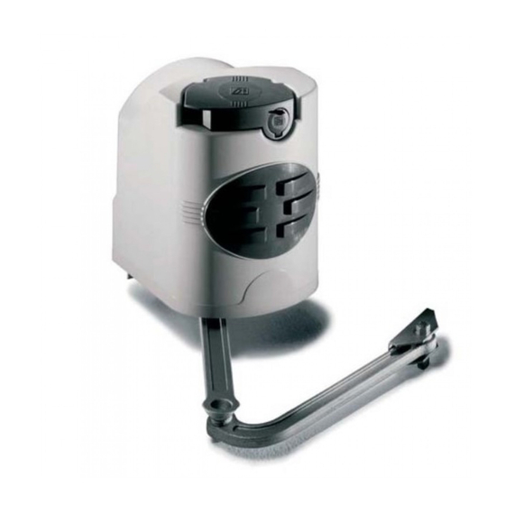
Description of parts Gearmotor Post-fastening bracket Articulated arm Gate-fastening bracket Standard installation Gearmotor Control panel Radiofrequency card Antenna Flashing light Selector Photocells Junction pit-box Mechanical stop plates 10. Transmitter... - Page 5 Dimensions and basic measurements General installation indications ⚠ Only skilled, qualified staff must install this product. Preliminary checks ⚠ Before beginning, do the following: • check that the gate structure is sturdy enough, the hinges work efficiently and that there is no friction between the fixed and moving parts; •...
- Page 6 INSTALLATION ⚠ The following illustrations are just examples, in that the space available for fitting the operator and accessories varies depending on the overall dimensions. It is up to the installer to find the most suitable solution. The drawing show an operator fitted on the left. Install the operator on the right, symmetrically. Corrugate tube laying Lay the corrugated tubes you will need for the cables coming out of the junction pit.
- Page 7 * See chapt. 4.4 Dimensions Opening angle Hinge Closing strike plate. 140÷205 0÷50 140÷195 75÷100 90° 140÷185 125÷150 140÷175 175÷200 180÷210 110° 200÷205 = 240 mm max. with 90° opening Installing the gearmotor Open the lock cover (1). Insert the key, push it down and turn it clockwise (2). Lift the cover, loosen the M4 hex nut and remove the cover from the gearmotor assembly (3).
- Page 8 Fit the gearmotor into the post-mounted bracket; match the four holes and fasten it using the two issued M8x90 screws and M8 nuts (4). M8x90 Applying the articulated arm - Fit and fasten the straight arm in to the gearmotor shaft using a plug, bolt and accompanying distancer. Lubricate the bushing, fi...
- Page 9 Gearmotor release To release the gearmotor, used the lever located above the rod. RELEASE LOCKING Adjusting the micro-switches See technical documentation of the ZL180 (319U17) control panel.
- Page 10 Electrical connections to the control panel Install the control panel and make the required electrical connections shown in the fi gure. ZL180 Cover mounting Once fi nished with mounting, electrical connections and adjustments, replace the cover and secure it using the hex M4 UNI5721 nut M4.
- Page 11 Installing and connections for outer opening Following, are the only things that change compared to a standard installation: Fastening the brackets Establish where you will fit the gate brace and measure where the gate-post brace will fit. Make sure to respect the quotas shown in the drawing and table.
-
Page 12: Troubleshooting
Electrical connections to the control panel Install the control panel and carry out the electrical connections as shown in the diagram. ZL180 Trouble shooting MALFUNCTIONS POSSIBLE CAUSES CHECKS AND FIXES The gate neither • No power supply • Check if network is up opens nor closes •... -
Page 13: Periodic Maintenance
Maintenance Periodic maintenance ☞ Before doing any maintenance, cut off the power supply, to prevent any hazardous situations caused by accidentally activating the operator. Periodic maintenance log kept by users (every six months) Date Notes Signature Extraordinary maintenance ⚠ The following table is for logging any extraordinary maintenance jobs, repairs and improvements performed by specialized contractors. ... -
Page 14: Phasing Out And Disposal
CAME S.p.A. employs a UNI EN ISO 14001 certified and compliant environmental protection system at its plants, to ensure that environmental safeguarding. We ask you to keep protecting the environment, as CAME deems it to be one of the fundamental points of its market operations strategies, by simply following these brief guidelines when disposing: DISPOSING THE PACKING MATERIALS The packing components (cardboard, plastic, etc.) are solid urban waste and may be disposed of without any particular difficulty, by... - Page 16 Came S.p.A. Came S.p.A. Via Martiri Della Libertà, 15 Via Cornia, 1/b - 1/c 31030 Dosson di Casier Dosson di Casier 33079 Sesto al Reghena Sesto al Reghena Treviso Treviso - Italy Pordenone Pordenone - Italy (+39) 0422 4940 (+39) 0434 698111...
Need help?
Do you have a question about the F7024N and is the answer not in the manual?
Questions and answers