Table of Contents
Advertisement
Advertisement
Table of Contents

Related Manuals for CAME FAST Series


Summary of Contents for CAME FAST Series
- Page 1 AUTOMATION FOR SWING GATES FAST SERIES INSTALLATION MANUAL F7024N...
-
Page 2: Legend Of Symbols
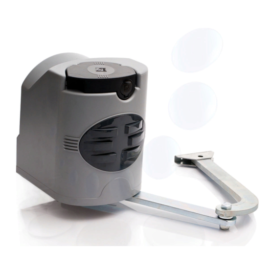
110° max 3 Reference Standards The company: CAME cancelli automatici is ISO 9001:2000 quality certified; is has also obtained the ISO 14001 environmen- tal safeguarding certification. CAME engineers and manufactures all of its products in Italy. This product complies with the following standards: EN 12978, UNI EN 954-1, CEI EN 60335-1, UNI EN 12453. - Page 3 4.3 Description of parts A1824 1) Operator 2) Pillar bracket 3) Articulated transmission arm 4) Gate bracket Dimensions and basic measurements Opening Gate stop angle Hinge 140÷205 0÷50 140÷195 75÷100 90° 140÷185 125÷150 140÷175 175÷200 180÷210 110° 200÷205 D = 240 mm. max Opened to 90°...
-
Page 4: Installation
5 Installation Installation must be carried out by expert qualified personnel and in full compliance with current regulations. 5.1 Preliminary checks Before installing, do the following: • Make sure you have a suitable omnipolar cut-off device with contacts more than 3 mm apart, and independent (sectioned off) power supply;... -
Page 5: Standard Installation
1) Automation 5.3 Standard installation 2) Control panel 3) Frequency card 4) Antenna 5) Flashing light 6) Selector switch 7) Photocells 8) Electric cable junction box 9) Mechanical stops 10)Transmitter 5.4 Tools and materials Make sure you have all the tools and materials you will need for the installation at hand to work in total safety and com- pliance with the current standards and regulations. -
Page 6: Installing The Gearmotor
5.5 Applying the base plate and A bracket - Secure the base plate to the pillar using M8 screws and ø14 mould inserts making sure the minimum distance of 100 mm is from the ground is met. - Secure the A bracket (using M6 screws or by welding) to the gate leaf making sure the C 68mm distance measurements and are met. - Page 7 Insert the gearmotor into the base plate’s 4 holes and secure it using the two supplied M8x90 screws and relative M8 nuts. M8x90 5.7 Applying the articulated arm - Insert and secure the straight arm into the gearmotor shaft including the pin with screw and relative spacer. Lubricate the bushing and insert the straight arm, joining it to the curved arm using the screw, washers and nut.
-
Page 8: Microswitch Assembly
5.8 Gearmotor release Before making any adjustments to the microswitches, you must release the gearmotor by turning the apposite handle. Handle Adjusting microswitches Closing-speed brake microswitch Upper cam Microswitch assembly Opening-speed brake microswitch Lower cam 5.9.1 Adjusting the opening stop 1) Release the gearmotor and manually lead the gate to its fullest opening position (max. - Page 9 5.9.2 Adjusting the closing-speed brake Once the opening endstop is adjusted, then you can adjust the closing-speed brake microswitch. Always with the gearmotor released ... 1) Manually lead the gate leaf to the fully closed position. 2) Turn the contoured cam until the micro switch is released as shown in the diagram. 3) Tighten the screws.
- Page 10 5.10 Electrical connections to the control panel Install the control panel and carry out the electrical connections as shown in the diagram. ZL180 Opening delayed gearmotor Closing delayed gearmotor...
- Page 11 5.11 Cover mounting Once fi nished with mounting, electrical connections and adjustments, replace the cover and secure it using the Ø3,9x13 screw. Insert the release handle into the ‘LOCK’ position and secure it. ø 3,9x13...
-
Page 12: Safety Instructions
6 Safety instructions Important safety instructions This product must only be employed for its originally intended use. Any other use is wrong and potentially dangerous. The manufacturer cannot be held liable for any damages resulting from wrongful, erroneous or negligent uses. Avoid working close to the hinges or other moving mechanical parts. -
Page 13: Periodic Maintenance
7 Maintenance 7.1 Periodic maintenance Periodic maintenance to be carried out by the end-user is as follows: wipe clean the glass surface of the photocells; check that the safety devices work properly; remove any obstructions. We suggest checking the state of lubrication and tightness of the anchoring screws on the operator. To check the efficiency of the safety devices, move an object in front of the photocells when gate is closing. -
Page 14: Extraordinary Maintenance
7.3 Maintenance Periodic maintenance log kept by the user (every 6 months) Date Notes Segnature 7.4 Extraordinary maintenance The following table is for logging any extraordinary maintenance, repairs or upgrades performed by licensed, specia- lised firms. N.B.: only entrust licensed, specialised firms to perform any extraordinary maintenance. Extraordinary maintenance log Installer’s stamp Operator name... -
Page 15: Conformity Declaration
We ask you to keep protecting the environment, as CAME deems it to be one of the fundamental points of its market operations strategies, by simply following these brief guidelines when disposing: DISPOSING THE PACKING MATERIALS The packing components (cardboard, plastic, etc.) are solid urban waste and may be disposed of without any particular diffi-... - Page 16 CAME UNITED KINGDOM LTD UNIT 3, ORCHARD BUSINESS PARK TOWN STREET, SANDIACRE NOTTINGHAM - NG10 5BP - U.K. Tel - 0044 115 9210430 Fax - 0044 115 9210431...
Need help?
Do you have a question about the FAST Series and is the answer not in the manual?
Questions and answers