
Related Manuals for CAME F7024E


Summary of Contents for CAME F7024E
- Page 1 AUTOMAZIONE AUTOMATION 11 9D V12E N 119 DV1 2 PER CANCELLI A BATTENTE FOR SWING GATES Italiano English Français Русский MANUALE D’INSTALLAZIONE INSTALLATION MANUAL F7024E...
- Page 2 HIS PRODUCT SHOULD ONLY BE USED FOR THE PURPOSE FOR WHICH IT WAS EXPLICITLY ONLY MAINTENANCE OPERATION TO DO WITH THE POWER ON ONSTANTLY CLEAN THE . CAME S. DESIGNED NY OTHER USE IS DANGEROUS IS NOT LIABLE FOR ANY DAMAGE •...
-
Page 3: Legend Of Symbols
Destination and conditions of use Intended use The F7024E operator is designed to power residential and condominium swing gates with gate leaves weighing up to 300 kg. Do not install or use unless as otherwise shown in this manual. Conditions of use We suggest you always fi... -
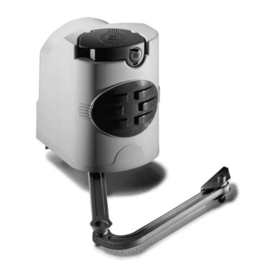
Page 4: Description Of Parts
Description of parts A1824 1) Operator 2) Pillar bracket 3) Articulated transmission arm 4) Gate bracket Standard installation 1) Gearmotor 2) Control panel 3) Frequency card 4) Antenna 5) Flashing light 6) Selector switch 7) Photocells 8) Electric cable junction box 9) Mechanical stops 10)Transmitter... - Page 5 Dimensions and basic measurements General installation indications ⚠ Only skilled, qualified staff must install this product. Preliminary checks ⚠ Before beginning, do the following: • check that the gate structure is sturdy enough, the hinges work efficiently and that there is no friction between the fixed and moving parts; •...
- Page 6 INSTALLATION ⚠ The following illustrations are just examples, in that the space available for fitting the operator and accessories varies depending on the overall dimensions. It is up to the installer to find the most suitable solution. The drawing show an operator fitted on the left. Install the operator on the right, symmetrically. Corrugate tube laying Lay the corrugated tubes you will need for the cables coming out of the junction pit.
-
Page 7: Installing The Gearmotor
See “Basic measure”, p. 3 Gate stop Hinge Opening angle 140÷205 0÷50 140÷195 75÷100 90° 140÷185 125÷150 140÷175 175÷200 180÷210 110° D = 240 mm. max 200÷205 Opened to 90° Installing the gearmotor Open the lock cover (1). Insert the key, push it down and turn it clockwise (2). Lift the cover, loosen the M4 hex nut and remove the cover from the gearmotor assembly (3). - Page 8 Insert the gearmotor into the pillar bracket’s 4 holes and secure it using the two supplied M8x90 screws and relative M8 nuts. M8x90 Applying the articulated arm - Insert and secure the straight arm into the gearmotor shaft including the pin with screw and relative spacer. Lubricate the bushing and insert the straight arm, joining it to the curved arm using the screw, washers and nut.
- Page 9 Gearmotor release To release or lock the gearmotor, use the level atop the small arm. RELASING LOCKING Adjusting the micro-switches Adjustment to be performed when gearmotor is released (see gearmotor release). If the system is fi tted with mechanical stops do not lock the cams. Contrarily adjust the cams as follows: Upper cam Lower cam securing screw microswitch...
- Page 10 Operator fitted on the left. With the gearmotor released and with the gate-leaf open at maximum 110°, turn the lower cam clockwise until the micro-switch activates. Fasten the cam by tightening the center screw. Close the gate leaf,turn the upper cam counter-clockwise until the micro-switch activates. Fasten the cam by tighte- ning the center screws.
- Page 11 Electrical connections to the control panel Install the control panel and carry out the electrical connections as shown in the diagram. ZLJ24 230V 230V ADT06 ADT06 M1 N1 E1 + E - M2 N2 E2 + E - SX (Left) DX (Right) Gearmotor fi...
-
Page 12: Fastening The Brackets
Installing and connections for outer opening Following, are the only things that change compared to a standard installation: Fastening the brackets Establish where you will fit the gate brace and measure where the gate-post brace will fit. Make sure to respect the quotas shown in the drawing and table. - Page 13 Adjusting the micro-switches Operator fitted on the left. With the gearmotor released and with the gate-leaf closed,turn the lower cam clockwise until the micro-switch activates. Fasten the cam by tightening the center screw. With the gearmotor released and with the gate-leaf open at maximum 110°, turn the lower cam counter-clockwise until the micro-switch activates.
-
Page 14: Troubleshooting
Electrical connections to the control panel Install the control panel and carry out the electrical connections as shown in the diagram. ZLJ24 230V 230V ADT06 ADT06 M1 N1 E1 + E - M2 N2 E2 + E - SX (Left) DX (Right) Gearmotor fi... -
Page 15: Periodic Maintenance
Maintenance Periodic maintenance ☞ Before doing any maintenance, cut off the power supply, to prevent any hazardous situations caused by accidentally activating the operator. Periodic maintenance log kept by users (every six months) Date Notes Signature Extraordinary maintenance ⚠ The following table is for logging any extraordinary maintenance jobs, repairs and improvements performed by specialized contractors. ... -
Page 16: Phasing Out And Disposal
CAME S.p.A. employs a UNI EN ISO 14001 certified and compliant environmental protection system at its plants, to ensure that environmental safeguarding. We ask you to keep protecting the environment, as CAME deems it to be one of the fundamental points of its market operations strategies, by simply following these brief guidelines when disposing: DISPOSING THE PACKING MATERIALS The packing components (cardboard, plastic, etc.) are solid urban waste and may be disposed of without any particular difficulty, by simply...
Need help?
Do you have a question about the F7024E and is the answer not in the manual?
Questions and answers