Table of Contents
Advertisement
Advertisement
Table of Contents

Related Manuals for CAME F7000


Summary of Contents for CAME F7000
- Page 1 11 9 DS 5 5 EN SWING GATE OPERATOR INSTALLATION MANUAL F7000 English...
- Page 2 • Employ this product only for the use for which it was expressly made. are working properly. This is the only maintenance operation to do with Any other use is dangerous. CAME S.p.A. is not liable for any damage cau- the power on. Constantly clean the photocells' glass covers using a slightly sed by improper, wrongful and unreasonable use •...
-
Page 3: Legend Of Symbols
2 Intended use and limits to use 2.1 Intended use The F7000 operator is designed and built by CAME S.p.A. in compliance with current safety regulations, to automate residential property and apartment building swing-gates. Any installation and use other than that specified in this manual is forbidden. -
Page 4: Description Of Parts
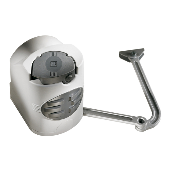
4.3 Description of parts Operator Post-fastening bracket Articulated arm Gate-fastening bracket 4.4 Dimensions (mm) Opening angle Closing Hinge 137÷210 strike plate 137÷205 Post 137÷200 137÷195 90° 137÷190 137÷185 137÷180 180÷175 180÷210 110° 200÷205 = 240 mm max. with 90° opening... -
Page 5: Installation
5 Installation Installation must be carried out by skilled, qualified technicians in accordance with current regulations. 5.1 Preliminary checks Before beginning installation, proceed as follows: • Set up a suitable omnipolar cut-off device, with distances greater than 3 mm between contacts, to disconnect the power supply. •... -
Page 6: Standard Installation
5.3 Standard installation Operator Antenna Flashing light Key switch Photocells Connections junction pit Mechanical stop plates Transmitter 5.4 Tools and equipment Make sure you have all the tools and materials needed to carry out the installation in total safety and in accordance with current regulations. -
Page 7: Installing The Gearmotor
5.5 Applying brackets for fastening to the gate post - Fasten the bracket to the post using M8 screws and ø 14 plugs while respecting the 100 mm minimum distance from the ground. - Fasten bracket A to the gate leaf by welding it or using M6 screws and respecting the measurements in the table 2.2 Limitations to use and the 68 mm level-diff erence between the two brackets Gate bracket A Post bracket... - Page 8 Insert the operator into the post-mounted bracket; match the four holes and fasten it using the two issued M8x90 screws and M8 nuts (4). M8x90 5.7 Applying the articulated arm - Insert the Ø 10x40 pin and the straight arm into the gearmotor shaft and fasten it using an M10x14 screw and Ø...
- Page 9 5.8 Releasing the gearmotor To release the gearmotor, used the lever located above the rod. RELEASE LOCKING 5.9 Micro-switch settings If the system already has mechanical stops, do not lock the cams, otherwise calibrate them in the following way: Upper cam Lower cam fastening screw Micro-switch...
- Page 10 Micro-switch setting with right-side installed gearmotor (inside view) These settings require the gearmotor to be released (see releasing the gearmotor). Manually close the gate leaf, turn the lower cam clockwise until the micro-switch is activated. Use the central screw to fasten the cam.
- Page 11 Micro-switch setting with left-side installed gearmotor (inside view) These settings require the gearmotor to be released (see releasing the gearmotor). Manually open the gate leaf fully (max. 110°). Use the central screw to fasten the cam. Switch Micro-switch Lower cam fastening screw Lower cam Manually close the gate leaf, turn the lower cam counter clockwise until the micro switch is activated.
- Page 12 5.10 Electrical connections Earthing 5.10.1 Electrical connections to the on-board control panel with two-leaf swing gates LEFT gate leaf with delayed CLOSING F7000 F7001 RIGHT gate leaf with delayed CLOSING F7000 F7001...
- Page 13 5.10.2 Electrical connections to the on-board control panel with two-leaf gates LEFT gate leaf RIGHT gate leaf 5.11 Cover mounting Once fi nished with mounting, electrical connections and adjustments, replace the cover and secure it using the hex M4 UNI5721 nut M4.
-
Page 14: Intended Use
6.2 Description T EC HNI CAL DATA Power supply 230 V - 50/60 Hz Designed and built entirely by CAME S.p.A. Maximum allowed power load 320 W Power draw when idle 40 mA Power supply 230 V AC on terminals L1 and L2. The board is... -
Page 15: Main Components
6.3 Main components Connecting terminals Line fuse Accessories fuse Buttons to memorise radio code Trimmer for adjusting the delay of gearmotor 2 Working time adjuster trimmer Automatic closing time adjuster trimmer Features selector Radio frequency card socket 10. LED Warning! Before acting on the device, cut off the mains power supply. -
Page 16: Electrical Connections
6.4 Electrical connections Gearmotor Gearmotor 1 delayed when opening Gearmotor 2 delayed when closing U V W X Y E Power supply 11 10E L1 L2 Terminals for powering the Power supply to the 24V AC accessories. Overall 230V AC 50/60 Hz allowed power: 20W control panel Connection for the 12 V - 15W max electric lock... - Page 17 Warning devices Flashing light (contact rated for: 230V AC - 25W Max) Flashes while gate opens and closes. U V W X Y E Gate open warning light (contact rated for: 24 V - 3 W Max) Warns of open gate position, turns off when gate is closed. 11 10 Safety devices Delta-S...
-
Page 18: Selecting Features
Command devices Stop button (N.C. contact) Gate stop button with exclusion of automatic closing - to resume movement press command button or transmitter button. If unused, short-circuit contact 1-2. if unused Key selector switch and/or command button (N.O. contact) Commands for opening and closing, by pressing the button or turning the selector switch key. -
Page 19: Activating The Radio Command
6.7 Activating the radio command Connect the RG58 antenna cable to the corresponding terminals. Only for the AF43S / AF43SM radio-frequency cards: position jumper as shown depending on the series of transmitters you are using. Plug the radio-frequency card into the control board AFTER CUTTING OFF THE MAINS POWER SUPPLY (and disconnecting the batteries, if any). - Page 20 Memorisation Hold down the “PROG” button on the CONTROL BOARD (the LED fl ashes). PROG Flashing LED AF radio frequency card A transmitter button sends the code, and the LED stays lit to show that memorisation has been successful. PROG LED on AF radio frequency card N.B.: if you later wish to change code, repeat the described sequence.
-
Page 21: Extraordinary Maintenance
9.3 Maintenance Periodic maintenance Before doing any maintenance, cut off the power supply, to prevent any hazardous situations caused by accidentally activating the operator. ☞ Periodic maintenance log kept by users (every six months) Date Notes Signature 9.4 Extraordinary maintenance The following table is for logging any extraordinary maintenance jobs, repairs and improvements performed by specialized contractors. -
Page 22: Troubleshooting
Installer's stamp Product name Date of job Technician's signature Customer's signature Job carried out _______________________________________________________________________________________ __________________________________________________________________________________________________ _______________________________________________________________________________________________ Installer's stamp Product name Date of job Technician's signature Customer's signature Job carried out _______________________________________________________________________________________ __________________________________________________________________________________________________ _______________________________________________________________________________________________ Installer's stamp Product name Date of job Technician's signature Customer's signature Job carried out _______________________________________________________________________________________... -
Page 23: Dismantling And Disposal
On its premises, CAME S.p.A. implements a certified Environmental Management System in compliance with the UNI EN ISO 14001 standard to ensure environmental protection. Please help us to safeguard the environment. At CAME we believe this to be one of the fundamentals of our operational and market development strategies. Just follow these short disposal instructions: DISPOSING OF THE PACKAGING The components of the packaging (i.e. - Page 24 HU • A vállalatra, termékeire és a műszaki szervizre vonatkozó minden további információért az Ön nyelvén: HR • Za sve dodatne informacije o poduzeću, proizvodima i tehničkoj podršci: UK • Для отримання будь-якої іншої інформації про компанію, продукцію та технічну підтримку: www. came.com www. came.com CAME S.p.A.
Need help?
Do you have a question about the F7000 and is the answer not in the manual?
Questions and answers