
Related Manuals for CAME F7000


Summary of Contents for CAME F7000
- Page 1 AUTOMAZIONE PER CANCELLI A BATTENTE AUTOMAZIONE PER CANCELLI A BATTENTE FA 006 81 M 0 4 Italiano MANUALE D’INSTALLAZIONE English F7000 Français Русский...
- Page 2 USO PER IL QUALE È STATO ’ SEGNI DI USURA O DANNI ALLE STRUTTURE MOBILI AI COMPONENTI DELL AUTOMAZIONE . CAME ESPRESSAMENTE STUDIATO GNI ALTRO USO È DA CONSIDERARSI PERICOLOSO TUTTI I PUNTI E DISPOSITIVI DI FISSAGGIO AI CAVI E ALLE CONNESSIONI ACCESSIBILI ENERE NON È...
-
Page 3: Legenda Simboli
Destinazione d’uso e limiti d’impiego Destinazione d’uso L’automazione F7000 è stata progettata e costruita da CAME S.p.A. in conformità alle vigenti norme di sicurezza per motorizzare cancelli a battente per uso residenziale o condominiale. Ogni installazione e uso difformi da quanto indicato nel seguente manuale sono da considerarsi vietate. -
Page 4: Descrizione Delle Parti
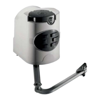
Descrizione delle parti Automazione Staff a di fi ssaggio al pilastro Braccio snodato Staff a di fi ssaggio al cancello Dimensioni (mm) Angolo di apertura Battuta Cerniera d’arresto 137÷210 137÷205 Pilastro 137÷200 137÷195 90° 137÷190 137÷185 137÷180 180÷175 180÷210 110° 200÷205 = 240 mm max. - Page 5 Indicazioni generali per l'installazione ⚠ L’installazione deve essere effettuata da personale qualificato ed esperto e nel pieno rispetto delle normative vigenti. Verifiche preliminari ⚠ Prima di procedere all’installazione è necessario: • verificare che la struttura del cancello sia adeguatamente robusta, le cerniere siano efficienti e che non vi siano attriti tra parti fisse e mobili; •...
-
Page 6: Impianto Tipo
Impianto tipo Automazione Antenna Lampeggiatore Selettore a chiave Fotocellule Pozzetto di derivazione collegamenti Battute di arresto meccanico Trasmettitore Attrezzi e materiali Assicurarsi di avere tutti gli strumenti e il materiale necessario per effettuare l’installazione nella massima sicurezza e secondo le normative vigenti. In figura alcuni esempi di attrezzatura per l’installatore. - Page 7 Applicazione delle staffe per il fissaggio al pilastro e al cancello - Fissare la staff a di fi ssaggio al pilastro con viti M8 e tasselli ø 14 rispettando la quota minima di 100 mm dal suolo. - Fissare la staff a A all’anta del cancello, saldandola o utilizzando viti M6 e rispettando le quote della tabella 2.2 Limiti d’impiego e i 68 mm di dislivello tra le due staff e.
- Page 8 Inserire l’automazione nella staff a fi ssata al pilastro in corrispondenza dei 4 fori e fi ssarla con le due viti M8x90 e i dadi M8 in dotazione (4). M8x90 Applicazione del braccio snodato nell’albero del motoriduttore e fi ssarlo con la vite M10x14 e la rosetta Ø 10x35. - Inserire la spina Ø...
- Page 9 Sblocco motoriduttore Per sbloccare o bloccare il motoriduttore, servirsi della levetta posizionata sopra l’astina. SBLOCCO BLOCCO Regolazione dei microinterruttori Regolazioni da eseguire con motoriduttore sbloccato (vedi sblocco motoriduttore). Se nell’impianto sono presenti gli arresti meccanici non bloccare le camme, altrimenti intervenire nella registrazione delle stesse nel seguente modo: Vite di fi...
- Page 10 Automazione installata a sinistra. Con il motoriduttore sbloccato e con l’anta in apertura (max 110°), ruotare la camma inferiore in senso orario fino all’attivazione del micro. Fissare la camma con la vite centrale. Portare l’anta in chiusura, ruotare la camma superiore in senso anti-orario fino all’attivazione del micro. Fissare la camma con le viti laterali.
-
Page 11: Collegamenti Elettrici
Collegamenti elettrici Massa Collegamenti elettrici al quadro comando incorporato con cancello a due ante battenti Anta SINISTRA ritardata in CHIUSURA Bianco Rosso F7000 F7001 Anta DESTRA ritardata in CHIUSURA F7000 F7001... - Page 12 Collegamenti elettrici al quadro comando incorporato con cancello a un’anta battente Anta a SINISTRA Anta a DESTRA Montaggio coperchio Dopo aver ultimato le operazioni di montaggio, collegamenti elettrici e regola zioni, inserire il coperchio fi ssandolo con il M4 UNI5721 dado esagonale M4.
- Page 13 Ogni installazione e uso difformi da quanto indicato nel seguente manuale sono da considerarsi vietate. Descrizione DATI TECNI CI Alimentazione 230 V - 50/60 Hz Progettata e costruita da CAME S.p.A. Potenza massima ammessa 320 W Assorbimento a riposo 40 mA Alimentazione a 230 V AC sui morsetti L1 e L2. La scheda è...
-
Page 14: Componenti Principali
Componenti principali Morsettiere di collegamento Fusibile di linea Fusibile accessori Pulsante memorizzazione codice radio Trimmer di regolazione ritardo del 2° motoriduttore Trimmer di regolazione tempo di lavoro Trimmer di regolazione tempo di chiusura automatica Selettore funzioni Innesto scheda radiofrequenza 10. LED Attenzione! Prima di intervenire sul dispositivo, togliere la tensione di linea. - Page 15 Collegamenti elettrici Motoriduttore Motoriduttore 1 ritardato in apertura Motoriduttore 2 ritardato in chiusura U V W X Y E Alimentazione 11 10E L1 L2 Morsetti per l’alimentazione Alimentazione quadro degli accessori a 24 V AC. comando 230 V AC Potenza complessiva con- 50/60 Hz sentita: 20 W Collegamento elettroserratura (12 V - 15 W max)
- Page 16 Dispositivi di segnalazione Lampeggiatore (Portata contatto: 230 V AC - 25 W max) Lampeggia durante le fasi di apertura e chiusura del cancello. U V W X Y E Lampada spia cancello aperto (Portata contatto: 24 V - 3 W max) Segnala la posizione del cancello aperto, si spegne quando il cancello è...
- Page 17 Dispositivi di comando Pulsante di stop (contatto N.C.) Pulsante di arresto del cancello con l’esclusione del ciclo di chiusura automatica, per riprendere il movimento premere il pulsante o il tasto del trasmettitore. se non usato Se non utilizzato, cortocircuitare il contatto 1-2. Selettore a chiave e/o pulsante per comandi (contatto N.O.) Comandi per apertura e chiusura, premendo il pulsante o girando la chiave del selettore.
- Page 18 Attivazione del comando radio Collegare il cavo RG58 dell’antenna agli appositi morsetti. Solo per le schede di radiofrequenza AF43S / AF43SM: posizionare il jumper come illustrato a seconda della serie di trasmettitori utilizzata. Innestare la scheda di radiofrequenza sulla scheda elettronica DOPO AVER TOLTO LA TENSIONE (e scollegato le batterie se inserite). N.B.: La scheda elettronica riconosce la scheda di radiofrequenza solo quando viene alimentata.
- Page 19 Memorizzazione Tenere premuto il tasto PROG sulla SCHEDA ELETTRONICA (il LED lampeggia). PROG LED intermittente Scheda radiofrequenza AF Con un tasto del trasmettitore si invia il codice, e il LED rimane accesso a segnalare l’avvenuta memorizzazione. PROG LED acceso Scheda radiofrequenza AF N.B.: se in seguito si vuole cambiare codice, ripetere la sequenza descritta.
- Page 20 Installazione e collegamenti per apertura verso l’esterno Di seguito, le uniche operazioni che variano rispetto all’installazione standard: Fissaggio delle staffe Determinare il punto di fissaggio della staffa cancello e ricavare il punto di fissaggio della staffa pilastro, rispettando le quote riportate nel disegno e nella tabella.
- Page 21 Regolazione dei microinterruttori Automazione installata a sinistra. Con il motoriduttore sbloccato e con l’anta in chiusura, ruotare la camma inferiore in senso orario fi no all’ attivazione dell’interruttore del micro. Fissare la camma con la vite centrale. Portare manualmente l’anta in posizione di massima apertura (max. 110°), ruotare la camma superiore in senso anti-orario fi...
- Page 22 Collegamenti elettrici al quadro comando incorporato con cancello a due ante battenti Anta SINISTRA ritardata in CHIUSURA F7000 F7001 Anta DESTRA ritardata in CHIUSURA F7000 F7001 Collegamenti elettrici al quadro comando incorporato con cancello a un’anta battente Anta a SINISTRA...
-
Page 23: Manutenzione Periodica
Risoluzione dei problemi MALFUNZIONAMENTI POSSIBILI CAUSE VERIFICHE E RIMEDI Il cancello non apre • Manca alimentazione • Verificare la presenza di rete e non chiude • Il motoriduttore è sbloccato • Rivolgersi all’assistenza • Il trasmettitore ha la batteria scarica •... -
Page 24: Riferimenti Normativi
UNI EN ISO 14001 a garanzia del rispetto e della tutela dell’ambiente. Vi chiediamo di continuare l’opera di tutela dell’ambiente, che CAME considera uno dei fondamenti di sviluppo delle proprie strategie operative e di mercato, semplicemente osservando brevi indicazioni in materia di smaltimento: SMALTIMENTO DELL’IMBALLO... - Page 25 AUTOMAZIONE PER CANCELLI A BATTENTE SWING GATE OPERATOR FA 00681 - EN INSTALLATION MANUAL F7000 English...
- Page 26 HIS PRODUCT SHOULD ONLY BE USED FOR THE PURPOSE FOR WHICH IT WAS EXPLICITLY ONLY MAINTENANCE OPERATION TO DO WITH THE POWER ON ONSTANTLY CLEAN THE . CAME S. DESIGNED NY OTHER USE IS DANGEROUS IS NOT LIABLE FOR ANY DAMAGE •...
-
Page 27: Legend Of Symbols
Intended use and limits to use Intended use The F7000 operator is designed and built by CAME S.p.A. in compliance with current safety regulations, to automate residential property and apartment building swing-gates. Any installation and use other than that specified in this manual is forbidden. -
Page 28: Description Of Parts
Description of parts Operator Post-fastening bracket Articulated arm Gate-fastening bracket Dimensions (mm) Opening angle Closing Hinge 137÷210 strike plate 137÷205 Post 137÷200 137÷195 90° 137÷190 137÷185 137÷180 180÷175 180÷210 110° 200÷205 = 240 mm max. with 90° opening... - Page 29 General installation indications ⚠ Only skilled, qualified staff must install this product. Preliminary checks ⚠ Before beginning, do the following: • check that the gate structure is sturdy enough, the hinges work efficiently and that there is no friction between the fixed and moving parts; •...
-
Page 30: Standard Installation
Standard installation Operator Antenna Flashing light Key switch Photocells Connections junction pit Mechanical stop plates Transmitter Tools and equipment Make sure you have all the tools and materials needed to carry out the installation in total safety and in accordance with current regulations. -
Page 31: Installing The Gearmotor
Applying brackets for fastening to the gate post - Fasten the bracket to the post using M8 screws and ø 14 plugs while respecting the 100 mm minimum distance from the ground. - Fasten bracket A to the gate leaf by welding it or using M6 screws and respecting the measurements in the table 2.2 Limitations to use and the 68 mm level-diff erence between the two brackets Gate bracket A Post bracket... - Page 32 Insert the operator into the post-mounted bracket; match the four holes and fasten it using the two issued M8x90 screws and M8 nuts (4). M8x90 Applying the articulated arm into the gearmotor shaft and fasten it using an M10x14 screw and Ø 10x35 washer. - Insert the Ø...
- Page 33 Releasing the gearmotor To release the gearmotor, used the lever located above the rod. RELEASE LOCKING Micro-switch settings Adjustment to be performed when gearmotor is released (see gearmotor release). If the system already has mechanical stops, do not lock the cams, otherwise calibrate them in the following way: Lower cam fastening Upper cam screw...
- Page 34 Operator fitted on the left. With the gearmotor released and with the gate-leaf open at maximum 110°, turn the lower cam clockwise until the micro-switch activates. Fasten the cam by tightening the center screw. Close the gate leaf,turn the upper cam counter-clockwise until the micro-switch activates. Fasten the cam by tightening the center screws.
-
Page 35: Electrical Connections
Electrical connections Earthing Electrical connections to the on-board control panel with two-leaf swing gates LEFT gate leaf with delayed CLOSING White F7000 F7001 RIGHT gate leaf with delayed CLOSING F7000 F7001... - Page 36 Electrical connections to the on-board control panel with two-leaf gates LEFT gate leaf RIGHT gate leaf Cover mounting Once fi nished with mounting, electrical connections and adjustments, replace the cover and secure it using the hex M4 UNI5721 nut M4. Insert the release handle into the ‘LOCK’ position and secure it.
-
Page 37: Intended Use
Description TECHNI CAL DATA Power supply 230 V - 50/60 Hz Designed and built entirely by CAME S.p.A. Maximum allowed power load 320 W Power draw when idle 40 mA Power supply 230 V AC on terminals L1 and L2. The board is... -
Page 38: Main Components
Main components Connecting terminals Line fuse Accessories fuse Buttons to memorise radio code Trimmer for adjusting the delay of gearmotor Working time adjuster trimmer Automatic closing time adjuster trimmer Features selector Radio frequency card socket 10. LED Warning! Before acting on the device, cut off the mains power supply. - Page 39 Electrical connections Gearmotor Gearmotor 1 delayed when opening Gearmotor 2 delayed when closing U V W X Y E Power supply 11 10E L1 L2 Terminals for powering the Power supply to the 24V AC accessories. Overall 230V AC 50/60 Hz allowed power: 20W control panel Connection for the 12 V - 15W max electric lock...
- Page 40 Warning devices Flashing light (contact rated for: 230V AC - 25W Max) Flashes while gate opens and closes. U V W X Y E Gate open warning light (contact rated for: 24 V - 3 W Max) Warns of open gate position, turns off when gate is closed. 11 10 Safety devices Delta-S...
-
Page 41: Selecting Features
Command devices Stop button (N.C. contact) Gate stop button with exclusion of automatic closing - to resume movement press command button or transmitter button. If unused, short-circuit contact 1-2. if unused Key selector switch and/or command button (N.O. contact) Commands for opening and closing, by pressing the button or turning the selector switch key. -
Page 42: Activating The Radio Command
Activating the radio command Connect the RG58 antenna cable to the corresponding terminals. Only for the AF43S / AF43SM radio-frequency cards: position jumper as shown depending on the series of transmitters you are using. Plug the radio-frequency card into the control board AFTER CUTTING OFF THE MAINS POWER SUPPLY (and disconnecting the batteries, if any). - Page 43 Memorisation Hold down the “PROG” button on the CONTROL BOARD (the LED fl ashes). PROG Flashing LED AF radio frequency card A transmitter button sends the code, and the LED stays lit to show that memorisation has been successful. PROG LED on AF radio frequency card N.B.: if you later wish to change code, repeat the described sequence.
- Page 44 Installing and connections for outer opening Following, are the only things that change compared to a standard installation: Fastening the brackets Establish where you will fit the gate brace and measure where the gate-post brace will fit. Make sure to respect the quotas shown in the drawing and table.
- Page 45 Adjusting the micro-switches Operator fitted on the left. With the gearmotor released and with the gate-leaf closed,turn the lower cam clockwise until the micro-switch activates. Fasten the cam by tightening the center screw. With the gearmotor released and with the gate-leaf open at maximum 110°, turn the lower cam counter-clockwise until the micro-switch activates.
- Page 46 Electrical connections to the on-board control panel with two-leaf swing gates LEFT gate leaf with delayed CLOSING F7000 F7001 RIGHT gate leaf with delayed CLOSING F7000 F7001 Electrical connections to the on-board control panel with two-leaf gates LEFT gate leaf...
-
Page 47: Periodic Maintenance
Trouble shooting MALFUNCTIONS POSSIBLE CAUSES CHECKS AND FIXES The gate neither No power supply • Check if network is up opens nor closes The gearmotor is released • Call for assistance The transmitter battery is run down • Replace the batteries The transmitter is out of order •... -
Page 48: Phasing Out And Disposal
CAME S.p.A. employs a UNI EN ISO 14001 certified and compliant environmental protection system at its plants, to ensure that environmental safeguarding. We ask you to keep protecting the environment, as CAME deems it to be one of the fundamental points of its market operations strategies, by simply following these brief guidelines when disposing: DISPOSING THE PACKING MATERIALS The packing components (cardboard, plastic, etc.) are solid urban waste and may be disposed of without any particular difficulty, by... - Page 49 AUTOMAZIONE PER CANCELLI A BATTENTE AUTOMATISME POUR PORTAILS BATTANTS FA 006 81 -FR MANUEL D'INSTALLATION F7000 Français...
- Page 50 ATTENTION ! Instructions importantes pour la sécurité des personnes : À LIRE ATTENTIVEMENT ! VANT PROPOS APPAREIL E NETTOYAGE ET L ENTRETIEN QUE DOIT EFFECTUER L UTILISATEUR NE DOIVENT • C • C PAS ÊTRE CONFIÉS À DES ENFANTS LAISSÉS SANS SURVEILLANCE ONTRÔLER SOUVENT E PRODUIT NE DEVRA ÊTRE DESTINÉ...
- Page 51 Utilisation prévue et limites d'utilisation Utilisation prévue L’automatisme F7000 a été conçu et fabriqué par CAME S.p.A. conformément aux normes de sécurité en vigueur pour la motorisation de portails battants à usage résidentiel ou collectif. Toute installation et toute utilisation autres que celles qui sont indiquées dans ce manuel sont interdites.
-
Page 52: Description Des Parties
Description des parties Automatisme Étrier de fi xation au pilier Bras articulé Étrier de fi xation au portail Dimensions (mm) Angle d'ouverture Butée Charnière 137÷210 d'arrêt 137÷205 Pilier 137÷200 137÷195 90° 137÷190 137÷185 137÷180 180÷175 180÷210 110° 200÷205 = 240 mm max. avec ouverture à... - Page 53 Instructions générales pour l'installation ⚠ L’installation doit être effectuée par du personnel qualifié et dans le plein respect des normes en vigueur. Contrôles préliminaires ⚠ Avant de procéder à l'installation, il faut : • contrôler que la structure du portail est bien robuste, que les charnières sont efficaces et s'assurer de l'absence de tout frottement entre les parties fixes et les parties mobiles ;...
-
Page 54: Installation Type
Installation type Automatisme Antenne Clignotant Sélecteur à clé Photocellules Boîtier de dérivation des branchements Butées mécaniques Émetteur Outils et matériel S'assurer de disposer de tous les instruments et de tout le matériel nécessaire pour effectuer l'installation en toute sécurité et conformément aux normes en vigueur. - Page 55 Application des étriers de fixation au pilier et au portail - Fixer l'étrier de fi xation au pilier à l'aide de vis M8 et de chevilles ø 14 en respectant une hauteur minimum de 100 mm par rapport au sol. - Fixer l'étrier A au vantail du portail en le soudant ou en utilisant des vis M6 et en respectant les valeurs indiquées dans le tableau 2.2 Limites d'utilisation et les 68 mm de dénivellement entre les deux étriers.
- Page 56 Introduire l'automatisme dans l'étrier fi xé au pilier au niveau des 4 orifi ces et le fi xer à l'aide des deux vis M8x90 et des écrous M8 fournis (4). M8x90 Application du bras articulé dans l'arbre du motoréducteur et le fi xer à l'aide de la vis M10x14 et de la rondelle - Introduire le goujon Ø...
- Page 57 Réglage des minirupteurs Réglage à eff ectuer avec motoréducteur débloqué (voir déblocage motoréducteur). En présence de butées mécaniques dans l'installation, ne pas bloquer les cames ou bien les régler comme suit : Vis de fi xation de la came Came supérieure inférieure...
- Page 58 Fixer la came à l'aide de la vis centrale. Amener le vantail en position de fermeture, tourner la came supérieure dans le sens anti-horaire jusqu'à activation du micro-interrupteur. Fixer la came à l'aide des vis latérales.
-
Page 59: Branchements Électriques
Branchements électriques Masse Branchements électriques à l'armoire de commande incorporée avec portail à deux vantaux battants Vantail GAUCHE à FERMETURE retardée Blanc Rouge F7000 F7001 Vantail DROIT à FERMETURE retardée F7000 F7001... - Page 60 Branchements électriques à l'armoire de commande incorporée avec portail à un vantail battant Vantail à GAUCHE Vantail à DROITE Montage couvercle Après avoir terminé les opérations de montage, les conne- xions électriques et les réglages, insérez le couvercle en M4 UNI5721 le fi...
-
Page 61: Utilisation Prévue
DONNÉES TECHNIQUES Alimentation 230 V - 50/60 Hz Puissance maximale admise 320 W Conçue et fabriquée par la société CAME S.p.A. Absorption au repos 40 mA Alimentation à 230 VCA sur les bornes L1 et L2. La carte Puissance maximum pour accessoires à 24 V 20 W est protégée en entrée par un fusible de 5 A, tandis que les... -
Page 62: Composants Principaux
Composants principaux Barrettes de connexion Fusible de ligne Fusible accessoires Bouton de mémorisation code radio Trimmer de réglage retard du 2ème motoréducteur Trimmer de réglage du temps de fonctionnement Trimmer de réglage du temps de fermeture automatique Sélecteur fonctions Branchement carte radiofréquence 10. - Page 63 Branchements électriques Motoréducteur Motoréducteur 1 retardé durant la phase Motoréducteur 2 retardé durant la phase d'ouverture de fermeture U V W X Y E Alimentation 11 10E L1 L2 Bornes pour l'alimentation Alimentation tableau des accessoires à 24 VCA de commande 230 VCA Puissance totale admise : 50/60 Hz 20 W...
- Page 64 Dispositifs de signalisation Clignotant (Portée contact : 230 VCA - 25 W max.). Clignote durant les phases d'ouverture et de fermeture du portail. U V W X Y E Lampe-témoin portail ouvert (Portée contact : 24 V - 3 W max.) Signale la position du portail ouvert et s'éteint lorsque le portail est fermé.
- Page 65 Dispositifs de commande Bouton d'arrêt (contact N.F.) Bouton d'arrêt du portail avec désactivation du cycle de ferme- ture automatique ; pour reprendre le mouvement, appuyer sur le bouton ou sur la touche de l'émetteur. s'il n'est pas utilisé S'il n'est pas utilisé, court-circuiter le contact 1-2. Sélecteur à...
- Page 66 Activation de la commande radio Connecter le câble RG58 de l’antenne aux bornes spécifiques. Uniquement pour les cartes de radiofréquence AF43S / AF43SM : positionner le cavalier comme indiqué en fonction de la série d'émetteurs utilisée. Insérer la carte de radiofréquence sur la carte électronique APRÈS AVOIR MIS HORS TENSION (et déconnecté les batteries). N.B.
- Page 67 Mémorisation Maintenir la touche PROG enfoncée sur la CARTE ÉLECTRONIQUE (le VOYANT clignote). PROG Voyant intermittent Carte radiofréquence AF L'enfoncement d'une touche de l'émetteur permet l'envoi du code. Le VOYANT restera allumé pour signaler l'exécution eff ective de la mémorisation. PROG Voyant allumé...
- Page 68 Installation et connexions pour l'ouverture vers l'extérieur Les opérations décrites ci-après sont les seules qui varient par rapport à l’installation standard : Fixation des étriers Identifier le point de fixation de l'étrier portail et établir celui de l'étrier pilier en respectant les dimensions indiquées sur le dessin et dans le tableau.
- Page 69 Réglage des micro-interrupteurs Automatisme installé à gauche. Avec motoréducteur débloqué et vantail en phase de fermeture, tourner la came inférieure dans le sens horaire jusqu’à activation de l’interrupteur du micro-interrupteur. Fixer la came à l'aide de la vis centrale. Amener manuellement le vantail en position d'ouverture maximale (max. 110°), tourner la came supérieure dans le sens anti-horaire jusqu'à...
- Page 70 Branchements électriques à l'armoire de commande incorporée avec portail à deux vantaux battants Vantail GAUCHE à FERMETURE retardée F7000 F7001 Vantail DROIT à FERMETURE retardée F7000 F7001 Branchements électriques à l'armoire de commande incorporée avec portail à un vantail battant Vantail à...
-
Page 71: Entretien Périodique
Résolution des problèmes DÉFAUTS DE CAUSES POSSIBLES CONTRÔLES ET REMÈDES FONCTIONNEMENT Le portail ne s'ouvre • Absence d'alimentation • Contrôler l'alimentation pas ou ne se ferme • Le motoréducteur est débloqué secteur • La batterie de l’émetteur est déchargée • S'adresser à l'assistance •... -
Page 72: Références Normatives
_____________________________________________________________________________________________ Démolition et élimination CAME S.p.A. dispose au sein de son établissement d’un Système de Gestion de l’Environnement certifié et conforme à la norme UNI EN ISO 14001 pour garantir le respect et la sauvegarde de l’environnement. L’usager est prié de continuer cet effort de sauvegarde de l’environnement que CAME considère comme un des facteurs de développe- ment de ses stratégies de fabrication et commerciales, en suivant ces brèves indications concernant le recyclage:... - Page 73 AUTOMAZIONE PER CANCELLI A BATTENTE АВТОМАТИКА ДЛЯ РАСПАШНЫХ ВОРОТ FA00681-RU ИНСТРУКЦИЯ ПО МОНТАЖУ F7000 Русский...
- Page 74 . Л КОМПАНИИ Е ПОЗВОЛЯЙТЕ ДЕТЯМ ИГРАТЬ С АВТОМАТИКОЙ АБОТЫ ПО ЧИСТКЕ И ТО ИЗДЕЛИЕ ДОЛЖНО ИСПОЛЬЗОВАТЬСЯ ИСКЛЮЧИТЕЛЬНО ПО НАЗНАЧЕНИЮ ЮБОЕ . CAME S. ТЕХНИЧЕСКОМУ ОБСЛУЖИВАНИЮ КОТОРЫЕ ДОЛЖЕН ВЫПОЛНЯТЬ ПОЛЬЗОВАТЕЛЬ НЕЛЬЗЯ ДРУГОЕ ПРИМЕНЕНИЕ РАССМАТРИВАЕТСЯ КАК ОПАСНОЕ СНИМАЕТ С • С...
-
Page 75: Условные Обозначения
Назначение и ограничения по применению Назначение Автоматика F7000 была разработана и изготовлена компанией CAME S.p.A. для автоматизации распашных ворот в частном и коллективном жилом секторе в полном соответствии с действующими нормами безопасности. Запрещается использовать устройство не по назначению и устанавливать его методами, отличными от описанных... -
Page 76: Основные Компоненты
Основные компоненты Привод с блоком управления Монтажное основание Шарнирный рычаг Кронштейн крепления к воротам Габаритные размеры (мм) (mm) Угол открывания Механический Петля 137÷210 упор 137÷205 Столб 137÷200 137÷195 90° 137÷190 137÷185 137÷180 180÷175 180÷210 110° 200÷205 = 240 мм (макс.) с... - Page 77 Общие инструкции по монтажу ⚠ Монтаж должен производиться квалифицированным персоналом в полном соответствии с требованиями действующих норм безопасности. Предварительные проверки ⚠ Перед тем как приступить к монтажным работам, выполните следующее: • Проверьте, чтобы конструкция ворот была достаточно прочной, петли находились в исправном состоянии, а между подвижными и неподвижными...
- Page 78 Вариант типовой установки Привод с блоком управления Антенна Cигнальная лампа Ключ-выключатель Фотоэлементы безопасности Разветвительная коробка Механические упоры Брелок-передатчик Инструменты и материалы Перед началом монтажных работ убедитесь в наличии всех необходимых инструментов и материалов, которые позволят произвести установку системы в полном соответствии с действующими нормами безопасности. На рисунке представлен...
- Page 79 Установка монтажного основания и переднего кронштейна - Прикрепите монтажное основание к столбу посредством винтов M8 и дюбелей ø 14, соблюдая минимальное расстояние от земли 100 мм. - Прикрепите передний кронштейн A к створке ворот путем сварки или с помощью винтов M6, учитывая минимальные расстояния...
- Page 80 Установите привод в монтажное основание, прикрепленное к столбу, выровняв относительно 4 отверстий, и зафиксируйте с помощью двух прилагаемых винтов M8x90 и гаек M8 (4). M8x90 Крепление шарнирного рычага в вал привода и зафиксируйте с помощью винта M10x14 и шайбы Ø 10x35. - Вставьте...
- Page 81 Разблокировка привода Для блокировки или разблокировки привода необходимо использовать ручку, расположенную в верхней части. РАЗБЛОКИРОВАТЬ БЛОКИРОВАТЬ Регулировка микровыключателей Регулировки, выполняемые после разблокировки привода (см. "Разблокировка привода") Регулировка осуществляется с помощью фиксации кулачковых механизмов следующим образом: Винт крепления Верхний кулачковый механизм нижнего...
- Page 82 Левосторонняя автоматика Откройте створку (макс. 110°) при разблокированном приводе, поверните по часовой стрелке нижний кулачковый механизм вплоть до срабатывания микровыключателя. Закрепите кулачковый механизм с помощью центрального винта. Закройте створку, поверните против часовой стрелки верхний кулачковый механизм вплоть до срабатывания микровыключателя. Закрепите кулачковый механизм с помощью боковых винтов. Правосторонняя...
-
Page 83: Электрические Подключения
Электрические подключения Масса Электрические подключения к встроенному блоку управления двустворчатых распашных ворот Створка СЛЕВА с задержкой при ЗАКРЫВАНИИ Белый Красный F7000 F7001 Створка СПРАВА с задержкой при ЗАКРЫВАНИИ F7000 F7001... - Page 84 Электрические подключения к встроенному блоку управления одностворчатых распашных ворот Створка СЛЕВА Створка СПРАВА Монтаж крышки Выполнив монтажные работы, электрические подклю- чения и настройки, установите крышку обратно, зафик- M4 UNI5721 сировав ее с шестигранной гайки M4. Установите ручку разблокировки в положение "LOCK" и зафиксируйте ее.
- Page 85 Запрещается использовать устройство не по назначению и устанавливать его методами, отличными от описанных в настоящей инструкции. Описание ТЕХНИ ЧЕСК ИЕ ХА РАК ТЕРИ СТИ КИ Изделие разработано и изготовлено компанией CAME S.p.A. Электропитание ~230 В, 50/60 Гц Электропитание ~230 В подается на блок управления с Максимально допустимая мощность 320 Вт...
- Page 86 Основные компоненты Колодки подключений Входной предохранитель Предохранитель аксессуаров Кнопка программирования радиокода Регулировка времени задержки второго привода при закрывании Регулировка времени работы Регулировка времени автоматического закрывания Микропереключатель выбора режимов работы Разъем для установки платы радиоприемника 10. Светодиодный индикатор Внимание! Перед проведением каких- либо...
- Page 87 Электрические подключения Привод Привод 1 с "задержкой при Привод 2 с "задержкой при открывании" закрывании" U V W X Y E Электропитание 11 10E L1 L2 Контакты электропитания Электропитание блока аксессуаров, ~24 В Макс. управления ~230 В, допустимая 50/60 Гц суммарная...
- Page 88 Устройства сигнализации Сигнальная лампа (макс. нагрузка: ~230 В, 25 Вт) Сигнальная лампа мигает во время движения ворот. U V W X Y E Лампа-индикатор "Ворота открыты" (макс. нагрузка: 24 В, 3 Вт) Указывает на то, что ворота открыты; выключается после закрывания...
- Page 89 Устройства управления Кнопка "Стоп" (Н.З. контакты) Кнопка остановки движения ворот, исключающая цикл автоматического закрывания; для возобновления движения необходимо нажать на соответствующую кнопку управления или брелока-передатчика. если не используется Если функция не используется, замкните накоротко контакты 1-2 с помощью перемычки. Ключ-выключатель и/или кнопка пошагового управления (Н.О. контакты) Команды...
- Page 90 Активация радиоуправления Подключите антенный кабель RG58 к соответствующим контактам. Только для плат радиоприемника команд управления AF43S / AF43SM: установите перемычку так, как показано на рисунке, учитывая серию используемых брелоков-передатчиков. ОТКЛЮЧИТЕ ЭЛЕКТРОПИТАНИЕ или аккумуляторы (если они используются) и только после этого вставьте плату радиоприемника...
- Page 91 Программирование Нажмите и удерживайте кнопку PROG на ПЛАТЕ БЛОКА УПРАВЛЕНИЯ (светодиодный индикатор начинает мигать). PROG Светодиодный индикатор мигает Плата радиоприемника AF Нажмите кнопку программируемого брелока-передатчика для передачи кода. Если светодиодный индикатор загорелся ровным светом, процедура программирования была проведена успешно. PROG Светодиодный...
- Page 92 Монтаж привода с открыванием наружу Ниже приведены только те работы, которые отличаются от стандартной процедуры монтажа: Монтаж кронштейнов Определите место крепления переднего кронштейна и рассчитайте место крепления заднего кронштейна, соблюдая расстояния, указанные на рисунке и в таблице. Установочные размеры (мм) С...
- Page 93 Регулировка микровыключателей Левосторонняя автоматика Закройте створку при разблокированном приводе, поверните по часовой стрелке нижний кулачковый механизм вплоть до срабатывания микровыключателя. Закрепите кулачковый механизм с помощью центрального винта. Максимально откройте створку вручную (макс. 110°), поверните против часовой стрелки верхний кулачковый механизм вплоть до срабатывания концевого микровыключателя. Закрепите кулачковый механизм с помощью боковых...
- Page 94 Электрические подключения к встроенному блоку управления двустворчатых распашных ворот Створка СЛЕВА с задержкой при ЗАКРЫВАНИИ F7000 F7001 Створка СПРАВА с задержкой при ЗАКРЫВАНИИ F7000 F7001 Электрические подключения к встроенному блоку управления одностворчатых распашных ворот Створка СЛЕВА U V W X Y E Створка...
-
Page 95: Возможные Неисправности И Способы Их Устранения
Возможные неисправности и способы их устранения НЕИСПРАВНОСТЬ ВОЗМОЖНАЯ ПРИЧИНА СПОСОБ УСТРАНЕНИЯ Створка ворот не • Нет напряжения питания. • Включите электропитание. двигается. • Разблокирован привод. • Заблокируйте привод. • Разрядились батарейки брелока-передатчика. • Замените батарейки. • Сломан брелок-передатчик. • Обратитесь к установщику. •... - Page 96 Выполненные работы _____________________________________________________________________________________ _________________________________________________________________________________________________ Утилизация CAME S.p.A. имеет сертификат системы защиты окружающей среды UNI EN ISO 14001, гарантирующий экологическую безопасность на ее заводах. Мы просим, чтобы вы продолжали защищать окружающую среду. САМЕ считает одним из фундаментальных пунктов стра- тегии рыночных отношений выполнение этих кратких руководящих принципов: УТИЛИЗАЦИЯ...
Need help?
Do you have a question about the F7000 and is the answer not in the manual?
Questions and answers