CAME FROG Installation Manual
Hide thumbs
Also See for FROG:
- Installation manual (65 pages) ,
- Installation manual (12 pages) ,
- Installation manual (49 pages)

Related Manuals for CAME FROG


Summary of Contents for CAME FROG
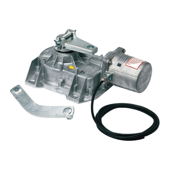
- Page 1 Swing-gate operator FA01570-EN FROG FROG-A FROG-AV FROG-AE INSTALLATION MANUAL EN English...
- Page 3 Machinery Directive (2006/42/EC) and with the reference harmonised technical standards are specified in the general CAME product catalogue or on the website www.came.com. • Make sure the mains power supply is disconnected during all installation procedures. • Check that the temperature ranges given are suitable for the installation site. • When excavating to lay the foundation box, ensure there is sufficient drainage to prevent water from stagnating inside it.
- Page 4 • If not already present, apply a permanent tag that describes how to use the manual release mechanism close to it. • Make sure that the operator has been properly adjusted and that the safety and protection devices and the manual release are working properly.
-
Page 5: Intended Use
This symbol shows what to tell users. The measurements, unless otherwise stated, are in millimetres. Description FROG-A Underground irreversible 230 V gearmotor with adjustable leaf-stop during closing, for swing gates with leaves up to 3.5 m in length and 400 kg in weight. FROG-AV Quick-version underground irreversible 230 V gearmotor with adjustable leaf-stop during closing, for swing gates with leaves up to 1.3 m in length and 300 kg in weight. -
Page 6: Usage Limitations
For multiple, sequential loads along the same line, recalculate the values in the table according to the actual power draw and distances. For information on connecting products not covered in this manual, please see the documentation accompanying the products themselves. To connect the encoder, use a FRORPU 3 x 0.5 mm² cable or a cable supplied by CAME on request (item code 801XA-0020). -
Page 7: Installation
INSTALLATION The following illustrations are examples only. The space available for fitting the operator and accessories varies depending on the area where it is installed. It is up to the installer to find the most suitable solution. The drawings refer to the right-side gearmotor. Preliminary operations The preliminary operations for installation concern the foundation box installation and the release devices fastening. - Page 8 Lubricate the transmission lever. Fit the transmission lever as shown in the drawings. Determining the travel end points with mechanical limit switches Manually open the leaf to the desired point. The leaf maximum opening is 110°. Unscrew the opening limit-switch point adjustment screw until it touches the foundation box. Tighten the nut to lock the screw into position.
-
Page 9: Electrical Connections
ELECTRICAL CONNECTIONS Before working on the control panel, disconnect the mains power supply and remove the batteries, if any. Provide IP67 junction boxes with terminal blocks for connections. Gear motor with encoder Blue cable Power supply cable Brown cable Encoder cable Black cable 801XA-0020 cable Yellow/green cable... - Page 10 Gearmotor without Encoder Blue cable Brown cable Black cable Yellow/green cable Check the correct direction of rotation of the gearmotor and, if necessary, invert the connection of the brown and black cables.
-
Page 11: Final Operations
FINAL OPERATIONS OUTWARDS OPENING The only operation that is different from the standard installation is described below. Setting up the gearmotor Insert the closing limit-switch point adjustment screw into the gearmotor arm. Gearmotor installed on the left Gearmotor installed on the right... - Page 12 CAME S.p.A. Via Martiri della Libertà, 15 31030 Dosson di Casier Treviso - Italy Tel. (+39) 0422 4940 Fax (+39) 0422 4941...
Need help?
Do you have a question about the FROG and is the answer not in the manual?
Questions and answers