CAME F7024N Installation Manual
Operator for swing gates
Hide thumbs
Also See for F7024N:
- Installation manual (17 pages) ,
- Installation manual (16 pages) ,
- Installation manual (17 pages)

Related Manuals for CAME F7024N


Summary of Contents for CAME F7024N
- Page 1 AUTOMAZIONE 11 9D U3 1 PER CANCELLI A BATTENTE Italiano English Français Русский MANUALE D’INSTALLAZIONE F7024N...
-
Page 2: Leggere Attentamente
• Il prodotto deve essere destinato solo all’uso per il quale è stato ogni sei mesi. Per controllare che le fotocellule funzionino, passare un espressamente studiato. Ogni altro uso è da considerarsi pericoloso. CAME oggetto davanti durante la chiusura; se l’automazione inverte il senso di S.p.A. -
Page 3: Legenda Simboli
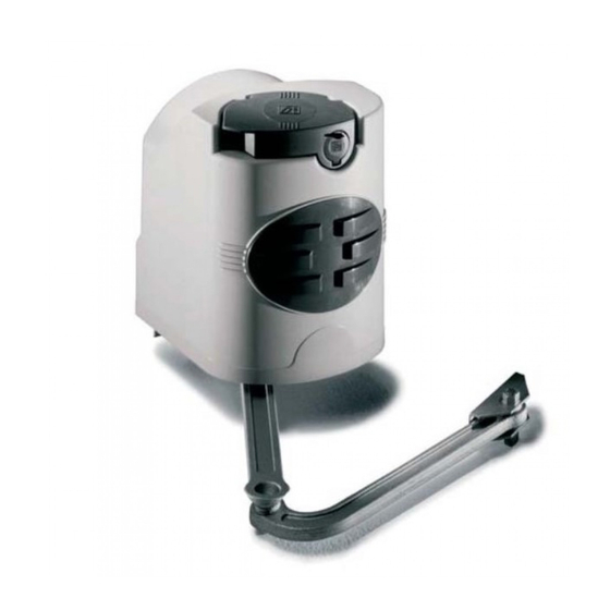
110° max 3 Riferimenti normativi CAME S.p.A. è una azienda certificata per il sistema di gestione della qualità aziendale ISO 9001:2000 e di gestione ambientale ISO 14001. CAME progetta e produce interamente in Italia. Il prodotto in oggetto è conforme alle seguenti normative: vedi dichiarazione di conformità. - Page 4 4.3 Descrizione delle parti Motoriduttore Staffa di fissaggio al pilastro Braccio snodato Staffa di fissaggio al cancello Dimensioni Angolo di apertura Cerniera Battuta d’arresto 140÷205 0÷50 140÷195 75÷100 90° 140÷185 125÷150 140÷175 175÷200 180÷210 110° 200÷205 = 240 mm max. con apertura a 90°...
-
Page 5: Installazione
5 Installazione L’installazione deve essere effettuata da personale qualificato ed esperto e nel pieno rispetto delle normative vigenti. 5.1 Verifiche preliminari Prima di procedere all’installazione dell’automazione è necessario: • Prevedere adeguato dispositivo di disconnesione onnipolare, con distanza maggiore di 3 mm tra i contatti, a sezionamento dell’alimentazione;... -
Page 6: Impianto Tipo
Motoriduttore 5.3 Impianto tipo Quadro comando Scheda radiofrequenza Antenna Lampeggiatore Selettore Fotocellule Pozzetto di derivazione Battute di arresto meccanico 10. Trasmettitore 5.4 Attrezzi e materiali Assicurarsi di avere tutti gli strumenti e il materiale necessario per effettuare l’installazione nella massima sicurezza e secondo le normative vigenti. - Page 7 5.5 Applicazione delle staffe per il fissaggio al pilastro e al cancello - Fissate la piastra base, utilizzando elementi di fi ssaggio scelti in relazione al tipo e ai materiali del pilastro. - Fissate la staff a A all’anta del cancello rispettando le quote della tabella 2.2 Limiti d’impiego e i 68 mm di dislivello tra le due staff e, utilizzando elementi di fi...
- Page 8 Inserire il motoriduttore nella staff a fi ssata al pilastro in corrispondenza dei 4 fori e fi ssarla con le due viti M8x90 e i dadi M8 in dotazione (4). M8x90 5.7 Applicazione del braccio snodato -Inserire e fi ssate il braccio diritto nell’albero motoriduttore utilizzando spina, vite e relativo distanziale. Lubrifi...
- Page 9 5.8 Sblocco motoriduttore Per sbloccare o bloccare il motoriduttore, servirsi della levetta posizionata sopra l’astina. SBLOCCO BLOCCO 5.9 Regolazione dei microinterruttori Vedi documentazione tecnica del quadro comando ZL180 (319U17).
- Page 10 5.10 Collegamenti elettrici al quadro comando Installare il quadro comando e procedere ai collegamenti elettrici come indicato in fi gura. ZL180 5.11 Montaggio coperchio Dopo aver ultimato le operazioni di montaggio, collegamenti elettrici e regola zioni, inserire il coperchio fi ssandolo con il M4 UNI5721 dado esagonale M4.
-
Page 11: Manutenzione Periodica
7 Manutenzione 7.1 Manutenzione periodica Gli interventi periodici a cura dell’utente sono: pulizia dei vetrini delle fotocellule; controllo del corretto funzionamento dei dispositivi di sicurezza; rimozione di eventuali intralci al corretto funzionamento dell’automazione. È consigliabile un controllo periodico alla lubrificazione e all’allentamento delle viti di fissaggio dell’automazione. Per controllare l’efficienza dei dispositivi di sicurezza, passare un oggetto davanti alle fotocellule durante la movimentazione in fase di chiusura. -
Page 12: Risoluzione Dei Problemi
7.2 Risoluzione dei problemi MALFUNZIONAMENTI POSSIBILI CAUSE VERIFICHE E RIMEDI Il cancello non apre • Manca alimentazione • Verificare la presenza di rete e non chiude • Il motoriduttore è sbloccato • Rivolgersi all’assistenza • Il trasmettitore ha la batteria scarica •... -
Page 13: Manutenzione Straordinaria
7.4 Manutenzione straordinaria La seguente tabella è destinata alla registrazione degli interventi di manutenzione straordinaria, di riparazione e di miglioramento, eseguiti da ditte esterne specializzate. N.B. Gli interventi di manutenzione straordinaria devono essere effettuati da tecnici specializzati. Registro manutenzione straordinaria Timbro installatore Nome operatore Data intervento... - Page 14 UNI EN ISO 14001 a garanzia del rispetto e della tutela dell’ambiente. Vi chiediamo di continuare l’opera di tutela dell’ambiente, che CAME considera uno dei fondamenti di sviluppo delle proprie strategie operative e di mercato, semplicemente osservando brevi indicazioni in materia di smaltimento: SMALTIMENTO DELL’IMBALLO...
-
Page 15: Dichiarazione Di Conformità
9 Dichiarazione di conformità Dichiarazione - CAME S.p.A. dichiara che questo prodotto è conforme ai requisiti essenziali e alle altre disposizioni pertinenti stabilite dalla direttiva 2006/42/CE e 2004/108/CE. Su richiesta è disponibile la copia conforme all’originale della dichiarazione di conformità. - Page 16 HU • A vállalatra, termékeire és a műszaki szervizre vonatkozó minden további információért az Ön nyelvén: HR • Za sve dodatne informacije o poduzeću, proizvodima i tehničkoj podršci: UK • Для отримання будь-якої іншої інформації про компанію, продукцію та технічну підтримку: www. came.com www. came.com CAME S.p.A.
- Page 17 OPERATOR 119D U3 1 EN FOR SWING GATES INSTALLATION MANUAL F7024N English...
-
Page 18: Read Carefully
• Cut other use is dangerous. CAME S.p.A. is not liable for any damage caused by off the power supply before releasing the operator for manual openings and improper, wrongful and unreasonable use •... -
Page 19: Legend Of Symbols
2 Intended use and limits to use 2.1 Intended use The F7024N gearmotor is engineered and built by CAME S.p.A. to comply with current safety laws and regulations, and to operate swing-gates in residential or apartment-block settings involving gate-leaves of no more than 300 kg. -
Page 20: Description Of Parts
4.3 Description of parts Gearmotor Post-fastening bracket Articulated arm Gate-fastening bracket Ddimensions Opening angle Hinge Closing strike plate. 140÷205 0÷50 140÷195 75÷100 90° 140÷185 125÷150 140÷175 175÷200 180÷210 110° 200÷205 = 240 mm max. with 90° opening... -
Page 21: Installation
5 Installation Installation must be carried by skilled, qualified technicians in accordance with current regulations. 5.1 Preliminary checks Before beginning to install, do the following: • Set up a suitable omnipolar cut-off device, with distances greater than 3 mm between contacts, wit sectioned power source; •... -
Page 22: Standard Installation
Gearmotor 5.3 Standard installation Control panel Radiofrequency card Antenna Flashing light Selector Photocells Junction pit-box Mechanical stop plates 10. Transmitter 5.4 Tools and equipment Make sure you have all the tools and materials needed to carry out the installation in total safety and in accordance with current regulations. -
Page 23: Installing The Gearmotor
5.5 Applying brackets for fastening to the gate post, using fastening elements suitable for the materials and post - Fasten the base plate, using fastening elements suitable for the materials and post. - Fasten bracket A to gate the leaf according to the measurements in the table. 2.2 Limitations to useand the 68 mm distance between the two brackets, Gate "A"... - Page 24 Fit the gearmotor into the post-mounted bracket; match the four holes and fasten it using the two issued M8x90 screws and M8 nuts (4). M8x90 5.7 Applying the articulated arm - Fit and fasten the straight arm in to the gearmotor shaft using a plug, bolt and accompanying distancer. Lubricate the bushing, fi...
- Page 25 5.8 Releasing the gearmotor To release the gearmotor, used the lever located above the rod. RELEASE LOCKING 5.9 Micro-switch settings See technical documentation of the ZL180 (319U17) control panel.
- Page 26 5.10 Electrical connections to the control panel Install the control panel and make the required electrical connections shown in the fi gure. ZL180 5.11 Cover mounting Once fi nished with mounting, electrical connections and adjustments, replace the cover and secure it using the hex M4 UNI5721 nut M4.
-
Page 27: Periodic Maintenance
7 Maintenance 7.1 Periodic maintenance The periodic maintenance actions to be done by the end users are: cleaning photocell glass; check proper working order of safety devices; remove any obstacles to the proper working order; We suggest to periodically check lubrication and tightness of fastening screws on the operator. To check efficiency of the safety devices, wave an object in front of the photocells during closing movement phase. -
Page 28: Troubleshooting
7.2 Troubleshooting MALFUNCTIONS POSSIBLE CAUSES CHECKS AND FIXES The gate neither • No power supply • Check if network is up opens nor closes • The gearmotor is released • Call for assistance • The transmitter battery is run down •... -
Page 29: Extraordinary Maintenance
7.4 Extraordinary maintenance The following table is for logging all extra-ordinary maintenance, repair and improvement jobs done by specialised contractors. N.B. All extraordinary maintenance jobs must be carried out by skilled technicians. Extraordinary maintenance log Installer’s stamp Operator name Date of job Technician’s segnature Requester’s segnature Job performed ________________________________________________________________________________________... -
Page 30: Dismantling And Disposal
On its premises, CAME S.p.A. implements a certified Environmental Management System in compliance with the UNI EN ISO 14001 standard to ensure environmental protection. Please help us to safeguard the environment. At CAME we believe this to be one of the fundamentals of ours market operations and development strategies. Just follow these short disposal instructions: DISPOSING OF THE PACKAGING The components of the packaging (i.e. -
Page 31: Compliance Statement
9 Compliance statement Declaration - CAME S.p.A. declares that this device complies with the essential requirements and other relevant provisions established in Directives 2006/42/CE e 2004/108/CE. Reference code for requesting a true copy: DDI B IT A001b... - Page 32 HU • A vállalatra, termékeire és a műszaki szervizre vonatkozó minden további információért az Ön nyelvén: HR • Za sve dodatne informacije o poduzeću, proizvodima i tehničkoj podršci: UK • Для отримання будь-якої іншої інформації про компанію, продукцію та технічну підтримку: www. came.com www. came.com CAME S.p.A.
- Page 33 AUTOMATISME 1 19 DU 31 F R POUR PORTAILS BATTANTS MANUEL D'INSTALLATION F7024N Français...
- Page 34 Toute autre utilisation est à considérer comme correctement. Il s'agit de l'unique opération d'entretien à eff ectuer avec dangereuse. La société CAME S.p.A. décline toute responsabilité en cas l'automatisme sous tension. Assurer un nettoyage constant des verres des d'éventuels dommages provoqués par des utilisations impropres, incorrectes...
-
Page 35: Limites D'utilisation
110° max. 3 Références normatives CAME S.p.A. est une société certifiée pour le système de gestion de la qualité ISO 9001:2000 et de gestion environnementale ISO 14001. La société Came conçoit et produit entièrement en Italie. Le produit en question est conforme aux normes suivantes : voir déclaration de conformité. -
Page 36: Description Des Parties
4.3 Description des parties Motoréducteur Étrier de fixation au pilier Bras articulé Étrier de fixation au portail Dimensions Angle d'ouverture Charnière Butée d'arrêt 140÷205 0÷50 140÷195 75÷100 90° 140÷185 125÷150 140÷175 175÷200 180÷210 110° 200÷205 = 240 mm max. avec ouverture à 90°... -
Page 37: Contrôles Préliminaires
5 Installation L’installation doit être effectuée par du personnel qualifié et dans le plein respect des normes en vigueur. 5.1 Contrôles préliminaires Avant d'installer l'automatisme, il faut : • Prévoir un dispositif de déconnexion omnipolaire spécifique, avec un espace de plus de 3 mm entre les contacts, pour le sectionnement de l'alimentation. -
Page 38: Installation Type
5.3 Installation type Motoréducteur Tableau de commande Carte radiofréquence Antenne Clignotant Sélecteur Photocellules Boîtier de dérivation Butées mécaniques 10. Émetteur 5.4 Outils et matériel S'assurer de disposer de tous les instruments et de tout le matériel nécessaire pour effectuer l'installation en toute sécurité et conformément aux normes en vigueur. - Page 39 5.5 Application des étriers de fixation au pilier et au portail - Fixer la plaque de base à l'aide des éléments de fi xation choisis en fonction du type et des matériaux du pilier. - Fixer l'étrier A au vantail du battant, en respectant les valeurs indiquées dans le tableau 2.2 Limites d'utilisation et les 68 mm de dénivellement entre les deux étriers, à...
- Page 40 Introduire le motoréducteur dans l'étrier fi xé au pilier au niveau des 4 orifi ces et le fi xer à l'aide des deux vis M8x90 et des écrous M8 fournis (4). M8x90 5.7 Application du bras articulé -Introduire et fi xer le bras droit dans l'arbre du motoréducteur à l'aide du goujon, de la vis et de l'entretoise correspondante. Lubrifi...
- Page 41 5.8 Déblocage motoréducteur Pour débloquer ou bloquer le motoréducteur, se servir de la poignée positionnée sur la tige. DÉBLOCAGE BLOCAGE 5.9 Réglage des minirupteurs Voir documentation technique de l'armoire de commande ZL180 (319U17).
- Page 42 5.10 Branchements électriques à l'armoire de commande Installer l'armoire de commande et réaliser les branchements électriques comme indiqué sur la fi gure. ZL180 5.11 Montage couvercle Après avoir terminé les opérations de montage, les conne- xions électriques et les réglages, insérez le couvercle en M4 UNI5721 le fi...
-
Page 43: Entretien Périodique
7 Entretien 7.1 Entretien périodique Les interventions périodiques devant être effectuées par l'utilisateur sont les suivantes : nettoyage des verres des photocellules, contrôle du bon fonctionnement des dispositifs de sécurité et élimination de tout obstacle pouvant compromettre le fonctionnement de l'automatisme. Il est conseillé... -
Page 44: Résolution Des Problèmes
7.2 Résolution des problèmes DÉFAUTS DE FONC- CAUSES POSSIBLES CONTRÔLES ET REMÈDES TIONNEMENT Le portail ne s'ouvre • Absence d'alimentation • Contrôler l'alimentation secteur pas ou ne se ferme • Le motoréducteur est débloqué • S'adresser à l'assistance • La batterie de l'émetteurl est déchargée •... -
Page 45: Entretien Curatif
7.4 Entretien curatif Le tableau suivant permet d'enregistrer les interventions d'entretien curatif, de réparation et d'amélioration effectuées par des sociétés externes spécialisées. N.B. les interventions d'entretien curatif doivent être effectuées par des techniciens qualifiés. Registre entretien curatif Cachet de l’installateur Nom de l’opérateur Date de l’intervention Signature du technicien... - Page 46 8 Mise au rebut et élimination CAME S.p.A. adopte dans ses établissements un Système de Gestion Environnementale certifié et conforme à la norme UNI EN ISO 14001 qui garantit le respect et la sauvegarde de l'environnement. Nous vous demandons de poursuivre ces efforts de sauvegarde de l'environnement, que CAME considère comme l'un des fondements du développement de ses propres stratégies opérationnelles et de marché, en observant tout simplement de brèves...
-
Page 47: Déclaration De Conformité
9 Déclaration de conformité Déclaration - CAME S.p.A. déclare que ce produit est conforme aux exigences essentielles et aux dispositions pertinentes établies par les directives 2006/42/CE et 2004/108/CE. La copie conforme à l’original de la déclaration de conformité est disponible sur demande. - Page 48 HU • A vállalatra, termékeire és a műszaki szervizre vonatkozó minden további információért az Ön nyelvén: HR • Za sve dodatne informacije o poduzeću, proizvodima i tehničkoj podršci: UK • Для отримання будь-якої іншої інформації про компанію, продукцію та технічну підтримку: www. came.com www. came.com CAME S.p.A.
-
Page 49: Инструкция По Монтажу
АВТОМАТИКА 119 DU3 1R U ДЛЯ РАСПАШНЫХ ВОРОТ ИНСТРУКЦИЯ ПО МОНТАЖУ F7024N Русский... - Page 50 подключениях. Следите за чистотой и смазкой механизмов движения • Данное изделие должно использоваться исключительно по назначению. (петель) и скольжения (направляющих) • Выполняйте функциональную Любое другое применение рассматривается как опасное. CAME S.p.A. проверку работы фотоэлементов и чувствительных профилей каждые снимает с себя всякую ответственность за возможный ущерб, нанесенный...
-
Page 51: Условные Обозначения
Этот символ обозначает раздел, предназначенный для ознакомления конечного пользователя. 2. Назначение и ограничения по применению 2.1 Назначение Привод F7024N был разработан и изготовлен компанией CAME S.p.A..для автоматизации распашных ворот со створкой массой до 300 кг в частном и коллективном жилом секторе в полном соответствии с действующими нормами безопасности. -
Page 52: Основные Компоненты
4.3 Основные компоненты Привод Кронштейн крепления к столбу Шарнирный рычаг Кронштейн крепления к воротам Габаритные размеры Угол открывания Механический упор Петля 140÷205 0÷50 140÷195 75÷100 90° 140÷185 125÷150 140÷175 175÷200 180÷210 110° 200÷205 = 240 мм (макс.) с открыванием на 90°... -
Page 53: Предварительные Проверки
5. Монтаж Монтаж должен производиться квалифицированным персоналом в полном соответствии с требованиями действующих норм безопасности. 5.1 Предварительные проверки Перед началом монтажных работ выполните следующее: • Убедитесь в том, что питание блока управления осуществляется от отдельной линии с соответствующим автоматическим выключателем и расстояние между контактами не менее 3 мм. •... - Page 54 Привод 5.3 Вариант типовой установки Блок управления Плата радиоприемника Антенна Cигнальная лампа Кодонаборная клавиатура Фотоэлементы Разветвительная коробка Механические упоры 10. Брелок-передатчик 5.4 Инструменты и материалы Перед началом монтажных работ убедитесь в наличии всех необходимых инструментов и материалов, которые позволят произвести установку системы в полном соответствии с действующими нормами безопасности. На рисунке представлен минимальный...
- Page 55 5.5 Крепление заднего и переднего кронштейнов к столбу и воротам - Зафиксируйте монтажную пластину, используя крепежные детали, выбранные с учетом типа и особенностей поверхности столба. - Прикрепите кронштейн A к створке ворот, соблюдая расстояния, приведенные в таблице "2.2 Ограничения по применению", и...
- Page 56 Установите привод в кронштейн, прикрепленный к столбу, выровняв относительно 4 отверстий, и зафиксируйте с помощью двух прилагаемых винтов M8x90 и гаек M8 (4). M8x90 5.7 Крепление шарнирного рычага - Вставьте и зафиксируйте прямой рычаг в вале привода, используя штифт, винт и соответствующую дистанционную деталь. Смажьте...
- Page 57 5.8 Разблокировка привода Для блокировки или разблокировки привода необходимо использовать рычаг, расположенный над стержнем. РАЗБЛОКИРОВАТЬ БЛОКИРОВАТЬ 5.9 Регулировка микровыключателей См. техническую документацию на блок управления ZL180 (319U17).
- Page 58 5.10 Электрические подключения к блоку управления Установите блок управления и выполните электрические подключения, как показано на рисунке. ZL180 5.11 Монтаж крышки Выполнив монтажные работы, электрические подклю- чения и настройки, установите крышку обратно, зафик- M4 UNI5721 сировав ее с шестигранной гайки M4. Установите ручку разблокировки...
-
Page 59: Техническое Обслуживание
7. Техническое обслуживание 7.1 Периодическое техническое обслуживание, осуществляемое пользователем Пользователем должны периодически выполняться следующие работы: чистка фотоэлементов, контроль за правильной работой устройств безопасности и удаление помех из зоны действия автоматической системы. Кроме того, рекомендуется периодически проверять состояние смазки и надежность крепления оборудования. Чтобы... - Page 60 7.2 Возможные неисправности и способы их устранения НЕИСПРАВНОСТЬ ВОЗМОЖНАЯ ПРИЧИНА СПОСОБ УСТРАНЕНИЯ Створка ворот не • Нет напряжения питания. • Включите электропитание. двигается. • Разблокирован привод. • Обратитесь к установщику. • Разрядились батарейки брелока-передатчика. • Замените батарейки. • Сломан брелок-передатчик. •...
- Page 61 7.4 Внеплановое техническое обслуживание Эта таблица необходима для записи внеплановых работ по обслуживанию и ремонту оборудования, выполненных специализированными предприятиями. Важное примечание: специальное обслуживание должно осуществляться профессиональными и квалифицированными специалистами. Бланк регистрации работ по внеплановому техническому обслуживанию Место печати Компания Дата проведения работ Подпись...
- Page 62 8. Утилизация В качестве гарантии защиты и охраны окружающей среды компания CAME S.p.A. внедряет на территории своих учреждений систему управления окружающей средой, сертифицированную и полностью соответствующую международному стандарту UNI EN ISO 14001. Мы просим, чтобы вы продолжали защищать окружающую среду. САМЕ считает одним из фундаментальных пунктов...
- Page 63 9. Декларация Декларация - CAME S.p.A. заявляет, что настоящее изделие соответствует основным требованиям и положениям, установленным Директивами 2006/42/CE и 2004/108/CE. По требованию заказчика может быть предоставлена копия декларации, соответствующая оригиналу.
- Page 64 HU • A vállalatra, termékeire és a műszaki szervizre vonatkozó minden további információért az Ön nyelvén: HR • Za sve dodatne informacije o poduzeću, proizvodima i tehničkoj podršci: UK • Для отримання будь-якої іншої інформації про компанію, продукцію та технічну підтримку: www. came.com www. came.com CAME S.p.A.
Need help?
Do you have a question about the F7024N and is the answer not in the manual?
Questions and answers