
Related Manuals for CAME F7024E


Summary of Contents for CAME F7024E
- Page 1 AUTOMAZIONE 119 D V 12 PER CANCELLI A BATTENTE Italiano English Français Русский MANUALE D’INSTALLAZIONE F7024E...
-
Page 2: Leggere Attentamente
Ogni altro uso è da considerarsi pericoloso. CAME chiusura; se l’automazione inverte il senso di marcia o si blocca, le fotocellule CAME S.p.A. non è responsabile per eventuali danni causati da usi impropri, funzionano correttamente. Questa è l’unica operazione di manutenzione che va erronei ed irragionevoli •... -
Page 3: Legenda Simboli
2 Destinazione e condizioni d’impiego 2.1 Destinazione d’uso L’automazione F7024E è stata progettata per motorizzare cancelli a battente per uso residenziale o condominiale con peso anta fi no a 300 kg. Ogni installazione e uso difformi da quanto indicato nel seguente manuale sono da considerarsi vietate. -
Page 4: Descrizione Delle Parti
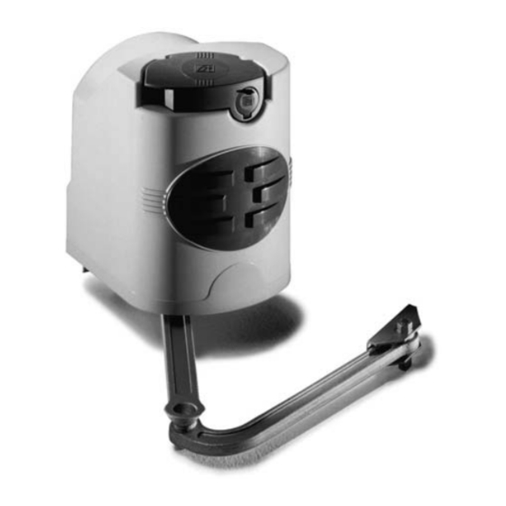
4.3 Descrizione delle parti F7024E 1) Motoriduttore 2) Staffa pilastro 3) Braccio di trasmissione snodato 4) Staffa cancello 4.4 Dimensioni e quote base Angolo di Battuta apertura d’arresto Cerniera 140÷205 0÷50 140÷195 75÷100 90° 140÷185 125÷150 140÷175 175÷200 180÷210 110°... -
Page 5: Installazione
5 Installazione L’installazione deve essere effettuata da personale qualificato ed esperto e nel pieno rispetto delle normative vigenti. 5.1 Verifiche preliminari Prima di procedere all’installazione dell’automatismo è necessario: • Prevedere adeguato dispositivo di disconnesione onnipolare, con distanza maggiore di 3 mm tra i contatti, a sezionamento dell’alimentazione;... -
Page 6: Impianto Tipo
5.3 Impianto tipo 1) Motoriduttore 2) Quadro comando 3) Scheda di frequenza 4) Antenna 5) Lampeggiatore 6) Selettore 7) Fotocellule 8) Pozzetto di derivazione collegamenti 9) Battute di arresto meccanico 10)Trasmettitore 5.4 Attrezzi e materiali Assicurarsi di avere tutti gli strumenti e il materiale necessario per effettuare l’installazione nella massima sicurezza e secondo le normative vigenti. - Page 7 5.5 Applicazione della staffa pilastro e della staffa cancello A - Fissare la staff e pilastro al pilastro con viti M8 e tasselli ø14 rispettando la quota minima di 100 mm. dalla pavimentazione. - Fissare la staff a cancello “A” (con viti M6 o saldatura) all’anta del cancello rispettando le quote della tabella a pag. 3 e i 68 mm di dislivello tra le 2 stafe.
- Page 8 Inserire il motoriduttore nella staff a pilastro in corrispondenza dei 4 fori e fi ssarlo con le due viti M8x90 e relativi dadi M8 in dotazione (4). M8x90 5.7 Applicazione del braccio snodato - Inserire e fi ssare il braccio diritto nell’albero motoriduttore compreso di spina con la vite e relativo distanziale. Lubrifi care la boccola e inserirla sul braccio dritto e unirlo con il braccio curvo utilizzando la vite, le rondelle e dado.
- Page 9 5.8 Sblocco motoriduttore Per sbloccare o bloccare il motoriduttore, servirsi della levetta posizionata sopra l’astina. SBLOCCO BLOCCO 5.9 Regolazione dei microinterruttori Regolazioni da eseguire con motoriduttore sbloccato (vedi sblocco motoriduttore). Se nell’impianto sono presenti gli arresti meccanici non bloccare le camme, altrimenti si interverviene nella registrazione delle stesse nel seguente modo: Vite di fi...
- Page 10 Regolazione dei microinterruttori con motoriduttore installato a destra (vista interna) Portare manualmente l’anta MICROINTERRUTTORE posizione di chiusura, ruotare in senso INTERRUTTORE orario la camma inferiore fi no all’ attivazione dell’interruttore del micro. Fissare la camma con la vite centrale. VITE DI FISSAGGIO CAMMA INFERIORE CAMMA INFERIORE Portare manualmente...
- Page 11 5.10 Collegamenti elettrici al quadro comando Installare il quadro comando e procedere ai collegamenti elettrici come indicato in fi gura. ZLJ24 230V 230V ADT06 ADT06 M2 N2 E2 + E - M1 N1 E1 + E - Motoriduttore montato a Motoriduttore montato a sinistra, azione ritardata in destra, azione ritardata in...
-
Page 12: Manutenzione Periodica
7 Manutenzione 7.1 Manutenzione periodica Gli interventi periodici a cura dell’utente sono: pulizia dei vetrini delle fotocellule; controllo del corretto funzionamento dei dispositivi di sicurezza; rimozione di eventuali intralci al corretto funzionamento dell’automazione. È consigliabile un controllo periodico alla lubrificazione e all’allentamento delle viti di fissaggio dell’automazione. Per controllare l’efficienza dei dispositivi di sicurezza, passare un oggetto davanti alle fotocellule durante la movimentazione in fase di chiusura. -
Page 13: Manutenzione Straordinaria
7.3 Manutenzione Registro manutenzione periodico a cura dell’utente (ogni 6 mesi) Data Annotazioni Firma 7.4 Manutenzione straordinaria La seguente tabella è destinata alla registrazione degli interventi di manutenzione straordinaria, di riparazione e di miglioramento, eseguiti da ditte esterne specializzate. N.B. Gli interventi di manutenzione straordinaria devono essere effettuati da tecnici specializzati. Registro manutenzione straordinaria Timbro installatore Nome operatore... -
Page 14: Smaltimento Dell'imballo
UNI EN ISO 14001 a garanzia del rispetto e della tutela dell’ambiente. Vi chiediamo di continuare l’opera di tutela dell’ambiente, che CAME considera uno dei fondamenti di sviluppo delle proprie strategie operative e di mercato, semplicemente osservando brevi indicazioni in materia di smaltimento: SMALTIMENTO DELL’IMBALLO... - Page 16 HU • A vállalatra, termékeire és a műszaki szervizre vonatkozó minden további információért az Ön nyelvén: HR • Za sve dodatne informacije o poduzeću, proizvodima i tehničkoj podršci: UK • Для отримання будь-якої іншої інформації про компанію, продукцію та технічну підтримку: www. came.com www. came.com CAME S.p.A.
- Page 17 AUTOMATION 119 DV1 2 EN FOR SWING GATES INSTALLATION MANUAL F7024E English...
-
Page 18: Read Carefully
• Employ this product only for the use for which it was expressly made. Any off the power supply before releasing the operator for manual openings and other use is dangerous. CAME S.p.A. is not liable for any damage caused by before any other operation, to prevent potentially hazardous situations. Read improper, wrongful and unreasonable use •... -
Page 19: Legend Of Symbols
2 Destination and conditions of use 2.1 Intended use The F7024E operator is designed to power residential and condominium swing gates with gate leaves weighing up to 300 kg. Do not install or use unless as otherwise shown in this manual. -
Page 20: Description Of Parts
4.3 Description of parts A1824 1) Operator 2) Pillar bracket 3) Articulated transmission arm 4) Gate bracket 4.4 Dimensions and basic measurements Opening angle Gate stop Hinge 140÷205 0÷50 140÷195 75÷100 90° 140÷185 125÷150 140÷175 175÷200 180÷210 110° 200÷205 D = 240 mm. max Opened to 90°... -
Page 21: Installation
5 Installation Installation must be carried out by expert qualified personnel and in full compliance with current regulations. 5.1 Preliminary checks Before installing, do the following: • Make sure you have a suitable omnipolar cut-off device with contacts more than 3 mm apart, and independent (sectioned off) power supply;... -
Page 22: Standard Installation
5.3 Standard installation 1) Gearmotor 2) Control panel 3) Frequency card 4) Antenna 5) Flashing light 6) Selector switch 7) Photocells 8) Electric cable junction box 9) Mechanical stops 10)Transmitter 5.4 Tools and materials Make sure you have all the tools and materials you will need for the installation at hand to work in total safety and compliance with the current standards and regulations. -
Page 23: Installing The Gearmotor
5.5 Applying the pillar bracket and A gate bracket - Secure the pillar bracket to the pillar using M8 screws and ø14 mould inserts making sure the minimum distance of 100 mm from the ground is met. - Fix gate bracket “A” (with M6 screws or by welding) to the gate leaf making sure the measurements mentioned in the table on page 3 and the 68 mm uneveness between the two brackets are met. - Page 24 Insert the gearmotor into the pillar bracket’s 4 holes and secure it using the two supplied M8x90 screws and relative M8 nuts. M8x90 5.7 Applying the articulated arm - Insert and secure the straight arm into the gearmotor shaft including the pin with screw and relative spacer. Lubricate the bushing and insert the straight arm, joining it to the curved arm using the screw, washers and nut.
- Page 25 5.8 Gearmotor release To release or lock the gearmotor, use the level atop the small arm. RELASING LOCKING 5.9 Adjusting the micro-switches Adjustment to be performed when gearmotor is released (see gearmotor release). If the system is fi tted with mechanical stops do not lock the cams. Contrarily adjust the cams as follows: Upper cam Lower cam securing screw microswitch...
- Page 26 SWITCH (maximum 110°), turn the upper cam counter-clockwise until the micro-switch is activated. Secure the came using the lateral screws. UPPER CAM SECURING SCREW UPPER CAM Adjusting the micro-switches with gearmotor installed on the left (inside view) Manually open the gate leaf fully MICROSWITCH (maximum 110°), turn the lower...
- Page 27 5.10 Electrical connections to the control panel Install the control panel and carry out the electrical connections as shown in the diagram. ZLJ24 230V 230V ADT06 ADT06 M2 N2 E2 + E - M1 N1 E1 + E - SX (Left) DX (Right) Gearmotor fi...
-
Page 28: Maintenance
7 Maintenance 7.1 Periodic maintenance Periodic maintenance to be carried out by the end-user is as follows: wipe clean the glass surface of the photocells; check that the safety devices work properly; remove any obstructions. We suggest checking the state of lubrication and tightness of the anchoring screws on the operator. To check the efficiency of the safety devices, move an object in front of the photocells when gate is closing. -
Page 29: Extraordinary Maintenance
7.3 Maintenance Periodic maintenance log kept by the user (every 6 months) Date Notes Signature 7.4 Extraordinary maintenance The following table is for logging any extraordinary maintenance, repairs or upgrades performed by licensed, specialised firms. N.B.: only entrust licensed, specialised firms to perform any extraordinary maintenance. Extraordinary maintenance log Installer’s stamp Technician’s name... -
Page 30: Phasing Out And Disposal
CAME S.p.A. employs a UNI EN ISO 14001 certified and compliant environmental protection system at its plants, to ensure that environmental safeguarding. We ask you to keep protecting the environment, as CAME deems it to be one of the fundamental points of its market operations strategies, by simply following these brief guidelines when disposing: DISPOSING THE PACKING MATERIALS The packing components (cardboard, plastic, etc.) are solid urban waste and may be disposed of without any particular difficulty, by... - Page 32 HU • A vállalatra, termékeire és a műszaki szervizre vonatkozó minden további információért az Ön nyelvén: HR • Za sve dodatne informacije o poduzeću, proizvodima i tehničkoj podršci: UK • Для отримання будь-якої іншої інформації про компанію, продукцію та технічну підтримку: www. came.com www. came.com CAME S.p.A.
-
Page 33: Manuel D'installation
AUTOMATISME 11 9D V1 2 F R POUR PORTAILS BATTANTS MANUEL D’INSTALLATION F7024E Français... - Page 34 Toute autre utilisation est à considérer comme d'articulation (charnières) et de frottement (glissières) doivent toujours être dangereuse. La société CAME CAME S.p.A.. décline toute responsabilité en cas lubrifi és et propres • Contrôler le bon fonctionnement des photocellules et des d'éventuels dommages provoqués par des utilisations impropres, incorrectes...
-
Page 35: Légende Des Symboles
3 Normes de référence CAME S.p.A. est une entreprise certifiée par le système de Gestion de la Qualité des Entreprises ISO 9001 et de Gestion de l’Environnement ISO 14001. Ce produit est conforme aux règlementations suivantes : voir Déclaration de conformité. -
Page 36: Description Des Parties
4.3 Description des parties A1824 1) Motoréducteur 2) Étrier pilier 3) Bras de transmission articulé 4) Étrier portail 4.4 Dimensions et cotes base Angle d’ouver- Butée d’arrêt ture Charnière 140÷205 0÷50 140÷195 75÷100 90° 140÷185 125÷150 140÷175 175÷200 180÷210 110° 200÷205 D = 240 mm. -
Page 37: Montage
5 Montage Le montage doit être effectué par du personnel qualifié et expérimenté et dans le respect des normes en vigueur. 5.1 Contrôles préliminaires Avant de procéder au montage, il est nécessaire de: • Prévoir un disjoncteur omnipolaire approprié, avec plus de 3 mm. de distance entre les contacts pour sélectionner l’alimentation; •... - Page 38 5.3 Installation Type 1) Motoréducteur 2) Armoire de commande 3) Carte de fréquence 4) Antenne 5) Clignotant de signalisation 6) Sélecteur 7) Photocellules 8) Boîte de dérivation pour connexions 9) Butée d’arrêt mécanique 10)Emetteur 5.4 Outils et matériel Assurez-vous d’avoir tous les outils et le matériel nécessaire pour effectuer le montage de l’automatisme en toute sécurité et con- formément aux normes en vigueur.
- Page 39 5.5 Application de l’étrier pilier et de l’étrier portail A - Fixez l’étrier pilier au pilier avec des vis M8 et des chevillesø14 en respectant la donnée minimale de 100 mm. du sol. - Fixez l’étrier portail ‘’A’’ (avec des vis M6 ou par soudure) à la porte du portail en respectant les données du tableau de la page 3 et les 68 mm.
- Page 40 Introduisez le motoréducteur dans la étrier pilier en face des 4 trous et fi xez-le avec les deux vis M8x90 et les écrous M8 correspon- dants fournis. M8x90 5.7 Application du bras articulé - Insérez et fi xez le bras droit dans l’arbre motoréducteur équipé de prise avec la vis et l’entretoise correspondante. Lubrifi ez la bague et introduisez-la sur le bras droit puis unissez-le au bras courbé...
- Page 41 Réglage à eff ectuer avec motoréducteur débloqué (voir déblocage motoréducteur). Si des arrêts mécaniques sont présents dans l’installation il ne faut pas bloquer les cames, sinon il faut les régler de la façon suivante : Vis de fi xage de la came Came supérieure inférieure...
- Page 42 INTERRUPTEUR 110°), tournez la came inférieure dans le sens des aiguilles d’une mon- tre jusqu’à l’activation de l’interrup- teur du micro. Fixez la came avec la vis centrale. VIS DE FIXAGE DE LA CAME INFÉRIEURE CAME INFÉRIEURE Placez manuellement le vantail en po-...
- Page 43 5.10 Connexions électriques à l’armoire de commande Installez l’armoire de commande et procédez aux connexions électriques comme sur le dessin. ZLJ24 230V 230V ADT06 ADT06 M2 N2 E2 + E - M1 N1 E1 + E - Motoréducteur monté à Motoréducteur monté...
-
Page 44: Maintenance Périodique
7 Maintenance 7.1 Maintenance périodique Les opérations périodiques à la charge de l’usager sont : nettoyage des lamelles de verre des photocellules, contrôle de l’état de marche des dispositifs de sécurité, élimination de tout ce qui peut empêcher le fonctionnement conforme de l’automatisme. Il est conseillé... - Page 45 7.3 Maintenance Registre des interventions périodiques de maintenance à la charge de l’usager (tous les six mois). Date Remarques Signature 7.4 Maintenance extraordinaire Le tableau ci-après est prévu pour l’inscription des interventions de maintenance extraordinaire, de réparation et d’amélioration, effectuées par des entreprises externes spécialisées. N.B.
-
Page 46: Élimination De L'emballage
__________________________________________________________________________________________________ 8 Démolition et élimination CAME S.p.A. dispose au sein de son établissement d’un Système de Gestion de l’Environnement certifié et conforme à la norme UNI EN ISO 14001 pour garantir le respect et la sauvegarde de l’environnement. L’usager est prié de continuer cet effort de sauvegarde de l’environnement que CAME considère comme un des facteurs de développe- ment de ses stratégies de fabrication et commerciales, en suivant ces brèves indications concernant le recyclage:... - Page 48 HU • A vállalatra, termékeire és a műszaki szervizre vonatkozó minden további információért az Ön nyelvén: HR • Za sve dodatne informacije o poduzeću, proizvodima i tehničkoj podršci: UK • Для отримання будь-якої іншої інформації про компанію, продукцію та технічну підтримку: www. came.com www. came.com CAME S.p.A.
-
Page 49: Инструкция По Монтажу
АВТОМАТИКА 119DV12RU ДЛЯ РАСПАШНЫХ ВОРОТ ИНСТРУКЦИЯ ПО МОНТАЖУ F7024E Русский... - Page 50 • Данное изделие должно использоваться исключительно по назначению. автоматической системы, местах крепления, проводке и доступных подключениях. Любое другое применение рассматривается как опасное. CAME S.p.A. снимает Следите за чистотой и смазкой механизмов движения (петель) и скольжения с себя всякую ответственность за возможный ущерб, нанесенный в результате...
-
Page 51: Условные Обозначения
2. Назначение и ограничения по применению 2.1 Назначение Привод F7024E разработан для автоматизации распашных ворот в частном секторе и кондоминиумах с массой створки до 300 кг. Запрещается использовать устройство не по назначению и устанавливать его методами, отличными от описанных в... -
Page 52: Основные Компоненты
4.3 Основные компоненты F7024E 1) Привод 2) Задний кронштейн 3) Шарнирный рычаг передачи 4) Передний кронштейн 4.4 Габаритные размеры и расстояния Угол откры- Механический вания упор Петля 140÷205 0÷50 140÷195 75÷100 90° 140÷185 125÷150 140÷175 175÷200 180÷210 110° 200÷205 D = 240 мм (макс.) -
Page 53: Предварительные Проверки
5. Монтаж Монтаж должен производиться квалифицированным персоналом в полном соответствии с требованиями действую- щих норм безопасности. 5.1 Предварительные проверки Перед началом монтажных работ выполните следующее: • Убедитесь в том, что питание блока управления осуществляется от отдельной линии с соответствующим автоматическим выключателем... - Page 54 5.3 Вариант типовой установки 1) Привод 2) Блок управления 3) Плата радиоприемника 4) Антенна 5) Сигнальная лампа 6) Ключ-выключатель 7) Фотоэлементы 8) Разветвительная коробка 9) Механические упоры 10) Брелок-передатчик 5.4 Инструменты и материалы Перед началом монтажных работ убедитесь в наличии всех необходимых инструментов и материалов, которые позволят произвести...
- Page 55 5.5 Монтаж переднего и заднего кронштейнов ворот A - Прикрепите задний кронштейн к столбу с помощью винтов ø8 и дюбелей ø14 на расстоянии не менее 100 мм над уровнем дорожного покрытия. - Прикрепите передний кронштейн A к створке ворот (с помощью болтов М6 или приварив), соблюдая расстояния, приведен- ные...
- Page 56 Установите привод в задний кронштейн, выровняв относительно 4 отверстий, и зафиксируйте с помощью двух прилагаемых винтов M8x90 и гаек M8 (4). M8x90 5.7 Крепление шарнирного рычага - Вставьте и зафиксируйте прямой рычаг в вале привода, используя штифт, винт и соответствующую дистанционную деталь. Смажьте...
- Page 57 5.8 Разблокировка привода Для блокировки или разблокировки привода необходимо использовать ручку, расположенную в верхней части. РАЗБЛОКИРОВАТЬ БЛОКИРОВАТЬ 5.9 Регулировка микровыключателей Регулировки, выполняемые после разблокировки привода (см. "Разблокировка привода") Если в системе предусмотрены механические упоры, не блокируйте кулачковые механизмы. В противном случае отрегулируй- те...
- Page 58 Регулировка концевых микровыключателей при правосторонней установке привода (вид изнутри) Закройте створку вручную, МИКРОВЫКЛЮЧАТЕЛЬ поверните по часовой стрелке ВЫКЛЮЧАТЕЛЬ нижний кулачковый механизм вплоть до срабатывания концевого микровыключателя. Закрепите кулачковый механизм с помощью центрального винта. ВИНТЫ КРЕПЛЕНИЯ НИЖНЕГО НИЖНИЙ КУЛАЧКОВЫЙ МЕХАНИЗМ КУЛАЧКОВОГО МЕХАНИЗМА Максимально...
- Page 59 5.10 Электрические подключения к блоку управления Установите блок управления и выполните электрические подключения, как показано на рисунке. ZLJ24 230V 230V ADT06 ADT06 M2 N2 E2 + E - M1 N1 E1 + E - Левый Правый Привод левосторонний с за- Привод...
-
Page 60: Техническое Обслуживание
7. Техническое обслуживание 7.1 Периодическое техническое обслуживание, осуществляемое пользователем Пользователем должны периодически выполняться следующие работы: чистка фотоэлементов, контроль за правильной работой устройств безопасности и удаление помех из зоны действия автоматической системы. Кроме того, рекомендуется периодически проверять состояние смазки и надежность крепления оборудования. Чтобы... - Page 61 7.3 Техническое обслуживание Бланк регистрации работ по периодическому техническому обслуживанию, заполняемый пользователем (каждые 6 месяцев) Дата Выполненные работы Подпись 7.4 Внеплановое техническое обслуживание Эта таблица необходима для записи внеплановых работ по обслуживанию и ремонту оборудования, выполненных спе- циализированными предприятиями. Важное примечание: ремонт оборудования должен осуществляться квалифицированными специалистами. Бланк...
-
Page 62: Утилизация Упаковки
Выполненные работы _________________________________________________________________________________ __________________________________________________________________________________________________ 8. Утилизация CAME S.p.A. имеет сертификат системы защиты окружающей среды UNI EN ISO 14001, гарантирующий экологическую безопасность на ее заводах. Мы просим, чтобы вы продолжали защищать окружающую среду. САМЕ считает одним из фундаментальных пунктов стра- тегии рыночных отношений выполнение этих кратких руководящих принципов: УТИЛИЗАЦИЯ... - Page 64 HU • A vállalatra, termékeire és a műszaki szervizre vonatkozó minden további információért az Ön nyelvén: HR • Za sve dodatne informacije o poduzeću, proizvodima i tehničkoj podršci: UK • Для отримання будь-якої іншої інформації про компанію, продукцію та технічну підтримку: www. came.com www. came.com CAME S.p.A.
Need help?
Do you have a question about the F7024E and is the answer not in the manual?
Questions and answers