
Related Manuals for CAME F7001


Summary of Contents for CAME F7001
- Page 1 AUTOMAZIONE 1 1 9 D U6 4 IT 1 1 9 D U 6 4 PER CANCELLI A BATTENTE Italiano English Français Русский MANUALE D’INSTALLAZIONE F7001 / F7001E Italiano...
- Page 2 Avvertimento (es. targa cancello). stato espressamente concepito. Ogni altro uso è da conside- Istruzioni e raccomandazioni rarsi quindi pericoloso. La CAME cancelli automatici s.p.a. non particolari per gli utenti è responsabile per eventuali danni causati da usi impropri, er- • Tenete libere da ingombri e pulite le aree di manovra del can- ronei ed irragionevoli •...
-
Page 4: Legenda Simboli
110° max 3 Riferimenti normativi Came Cancelli Automatici è una azienda certificata per il sistema di gestione della qualità aziendale ISO 9001 e di gestione ambientale ISO 14001. Came progetta e produce interamente in Italia. Il prodotto in oggetto è conforme alle seguenti normative: vedi Dichiarazione di conformità. -
Page 5: Descrizione Delle Parti
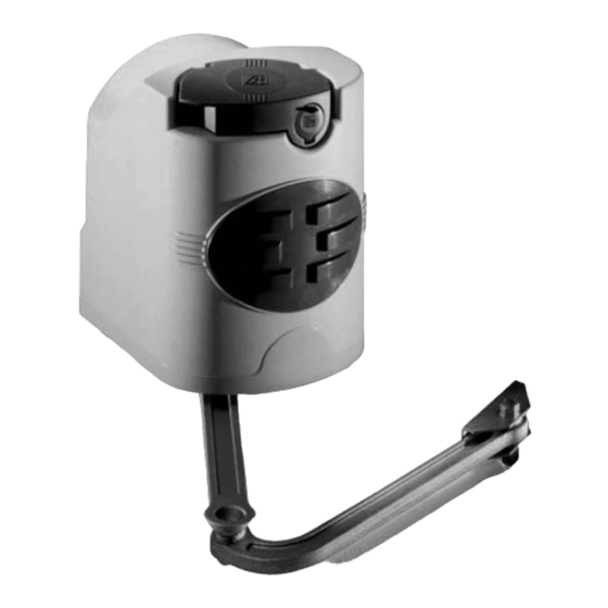
4.3 Descrizione delle parti 1) Motoriduttore 2) Staff a pilastro 3) Braccio di trasmissione snodato 4) Staff a cancello 4.4 Dimensioni e quote base Angolo di Battuta apertura Cerniera d’arresto 137÷210 137÷205 Pilastro 137÷200 137÷195 90° 137÷190 137÷185 137÷180 180÷175 180÷210 110°... -
Page 6: Installazione
5 Installazione L’installazione deve essere effettuata da personale qualificato ed esperto e nel pieno rispetto delle normative vigenti. 5.1 Verifiche preliminari Prima di procedere all’installazione dell’automatismo è necessario: • Prevedere adeguato dispositivo di disconnesione onnipolare, con distanza maggiore di 3 mm tra i contatti, a sezionamento dell’alimentazione;... -
Page 7: Impianto Tipo
5.3 Impianto tipo 1) Motoriduttore 2) Quadro comando 3) Scheda di frequenza 4) Antenna 5) Lampeggiatore di movimento 6) Selettore a chiave 7) Fotocellule di sicurezza 8) Pozzetto di derivazione collegamenti 9) Battute di arresto meccanico 10)Trasmettitore 5.4 Attrezzi e materiali Assicurarsi di avere tutti gli strumenti e il materiale necessario per effettuare l’installazione nella massima sicurezza e secondo le normative vigenti. - Page 8 5.5 Applicazione della staffa pilastro e della staffa cancello A - Fissare la staff a pilastro al pilastro con viti M8 e tasselli ø14 rispettando la quota minima di 100 mm. dalla pavimentazione. - Fissare la staff a cancello “A” (con viti M6 o saldatura) all’anta del cancello rispettando le quote della tabella a pag. 2 e i 68 mm di dislivello tra le due staff e.
- Page 9 Inserire il motoriduttore nella staff a cancello in corrispondenza dei 4 fori e fi ssarlo con le due viti M8x90 e relativi dadi M8 in dotazione (4). M8x90 5.7 Applicazione del braccio snodato - Inserire la spina Ø10x40 e il braccio diritto nell’albero del motoriduttore e fi ssarlo con la vite M10x14 e relativa rosetta Ø10x35. Lubrifi...
- Page 10 5.8 Sblocco motoriduttore Prima di cominciare le operazioni di regolazione dei microinterruttori, è necessario sbloccare il motoriduttore ruotando la relativa manopola. Manopola 5.9 Regolazione microinterruttori Microinterruttore superiore Camma superiore Microinterruttore inferiore Camma inferiore 5.9.1 Motoriduttore installato a sinistra (vista interna) STOP IN APERTURA 1) Sbloccare il motoriduttore e portare manualmente il cancello nella posizione di apertura desiderata (max.
- Page 11 STOP IN CHIUSURA Dopo aver regolato il fi necorsa in apertura, è possibile regolare il microinterruttore in chiusura. Sempre con il motoriduttore sbloccato ... 1) portare manualmente il cancello in posizione di chiusura. 2) Ruotare la CAMMA SUPERIORE in SENSO ANTIORARIO fi no all’attivazione dell’interruttore. 3) fi...
-
Page 12: Collegamenti Elettrici
STOP IN APERTURA Dopo aver regolato il fi necorsa in chiusura è possibile regolare il microinterruttore in apertura. Sempre con il motoriduttore sbloccato ... 1) Sbloccare il motoriduttore e portare manualmente il cancello nella posizione di apertura desiderata (max. 110°). 2) Ruotare la CAMMA SUPERIORE in SENSO ANTIORARIO fi... - Page 13 5.10.2 Collegamenti elettrici al quadro comando ZA3N (F7001) Installare il quadro comando e procedere ai collegamenti elettrici come indicato in fi gura. T . L . T . C . A . F U S I B I L E C E N T R A L I N A F U S .
-
Page 14: Indicazioni Di Sicurezza
6 Indicazioni di sicurezza Importanti indicazioni generali di sicurezza Questo prodotto deve essere destinato solo all’uso per il quale è stato espressamente studiato. Ogni altro uso è da considerarsi improprio e quindi pericoloso. Il costruttore non può essere considerato responsabile per eventuali danni causati da usi impropri, erronei ed irragionevoli. -
Page 15: Manutenzione Periodica
7 Manutenzione 7.1 Manutenzione periodica Gli interventi periodici a cura dell’utente sono: pulizia dei vetrini delle fotocellule; controllo del corretto funzionamento dei dispositivi di sicurezza; rimozione di eventuali intralci al corretto funzionamento dell’automazione. È consigliabile un controllo periodico alla lubrificazione e all’allentamento delle viti di fissaggio dell’automazione. Per controllare l’efficienza dei dispositivi di sicurezza, passare un oggetto davanti alle fotocellule durante la movimentazione in fase di chiusura. -
Page 16: Manutenzione Straordinaria
7.3 Manutenzione Registro manutenzione periodico a cura dell’utente (ogni 6 mesi) Data Annotazioni Firma 7.4 Manutenzione straordinaria La seguente tabella è destinata alla registrazione degli interventi di manutenzione straordinaria, di riparazione e di migliora- mento, eseguiti da ditte esterne specializzate. N.B. - Page 17 UNI EN ISO 14001 a garanzia del rispetto e della tutela dell’ambiente. Vi chiediamo di continuare l’opera di tutela dell’ambiente, che CAME considera uno dei fondamenti di sviluppo delle proprie strate- gie operative e di mercato, semplicemente osservando brevi indicazioni in materia di smaltimento: SMALTIMENTO DELL’IMBALLO...
- Page 18 HR • Za sve dodatne informacije o poduzeću, proizvodima i tehničkoj podršci: UK • Для отримання будь-якої іншої інформації про компанію, продукцію та технічну підтримку: www. came.com www. came.com CAME Cancelli Automatici S.p.a. CAME Cancelli Automatici S.p.a. Via Martiri Della Libertà, 15 31030 Dosson Di Casier...
- Page 19 AUTOMATION 11 9 DU 6 4 EN FOR SWING GATES INSTALLATION MANUAL F7001 / F7001E English...
-
Page 20: Read Carefully
Warning Sings (e.g. gate plate). (i.e. that for which it was expressly built for). Any other use is Special instructions and to be considered dangerous. Came Cancelli Automatici S.p.A. advice for users is not liable for any damage resulting from improper, wrongful •... -
Page 22: Legend Of Symbols
110° max 3 Reference Standards Came Cancelli Automatici is ISO 9001 and ISO 14001 Quality and Environmentally certified. Came entirely designs and manufactures its products in Italy. The product in question compliant to the following legislation: see Declaration of Compliance. - Page 23 4.3 Description of parts 1) Gearmotor 2) Pillar bracket 3) Articulated transmission arm 4) Gate bracket 4.4 Dimensions and basic measurements Opening angle 137÷210 137÷205 137÷200 137÷195 90° 137÷190 137÷185 137÷180 180÷175 180÷210 110° 200÷205...
-
Page 24: Preliminary Checks
5 Installation Installation must be carried out by expert qualified personnel and in full compliance with current regulations. 5.1 Preliminary checks Before installing, do the following: • Make sure you have suitable tubing and conduits for the electrical cables to pass through and be protected against mechanical damage;... -
Page 25: Standard Installation
5.3 Standard installation 1) Gearmotor 2) Control panel 3) Frequency card 4) Antenna 5) Flashing light 6) Keyswitch 7) Photocells 8) Electric cable junction box 9) Mechanical endstops 10)Transmitter 5.4 Tools and materials Make sure you have all the tools and materials you will need for the installation at hand to work in total safety and compliance with the current standards and regulations. -
Page 26: Installing The Gearmotor
5.5 Applying the pillar bracket and A gate bracket - Secure the pillar bracket to the pillar using M8 screws and ø14 mould inserts making sure the minimum distance of 100 mm from the ground is met. - Fix gate bracket “A” (with M6 screws or by welding) to the gate leaf making sure the measurements mentioned in the table on page 2 and the 68 mm uneveness between the two brackets are met. - Page 27 Insert the gearmotor into the Pillar bracket’s 4 holes and secure it with the two supplied M8x90 screws and relative M8 nuts (4). M8x90 5.7 Applying the articulated arm - Plug in the Ø10x40 plug and the straight arm into the gear motor shaft and secure it using the M10x14 screw and relative Ø10x35 washer.
- Page 28 5.8 Gearmotor release Before making any adjustments to the microswitches, you must release the gearmotor by turning the apposite handle. Handle 5.9 Adjusting microswitches Upper microswitch Upper cam Lower microswitch Lower cam 5.9.1 Motoriduttore installato a sinistra (vista interna) OPENING STOP 1) Release the gearmotor and manually lead the gate to the desired opening position (max.
- Page 29 CLOSING STOP After having adjusted the opening endpoint, you can adjust the closing microswitch. Always with the gearmotor released... 1) manually lead the gate leaf to the fully closed position. 2) turn the UPPER CAM COUNTER-CLOCKWISE until the switch is activated. 3) tighten the two screws.
-
Page 30: Electrical Connections
OPENING STOP After adjusting the closing endpoint you may adjust the opening microswitch. Always with the gearmotor released ... 1) Manually push the gate to the desired open position (max. 110°). 2) turn the UPPER CAM COUNTER-CLOCKWISE until the switch is activated. 3) tighten the two screws. - Page 31 5.10.2 Electrical connections to the ZA3N control panels (F7001) Install the control panel and carry out the electrical connections as shown in the diagram. T . L . T . C . A . F U S I B I L E C E N T R A L I N A F U S .
-
Page 32: Safety Instructions
6 Safety instructions Important safety instructions This product must only be employed for its originally intended use. Any other use is wrong and potentially dangerous. The manufacturer cannot be held liable for any damages resulting from wrongful, erroneous or negligent uses. Avoid working close to the hinges or other moving mechanical parts. -
Page 33: Periodic Maintenance
7 Maintenance 7.1 Periodic maintenance Periodic maintenance to be carried out by the end-user is as follows: wipe clean the glass surface of the photocells; check that the safety devices work properly; remove any obstructions. We suggest checking the state of lubrication and tightness of the anchoring screws on the operator. To check the efficiency of the safety devices, move an object in front of the photocells when gate is closing. -
Page 34: Extraordinary Maintenance
7.3 Maintenance Periodic maintenance log (for end-user) (every 6 moths) Date Notes Signature 7.4 Extra-ordinary maintenance The following table serves to note down any extra-ordinary maintenance, repairs or improvements performed by specialised firms. N.B.: Any extra-ordinary maintenance must be performed by specialised technicians. Extra-ordinary maintenance Installer’s stamp Technician’s name... -
Page 35: Phasing Out And Disposal
CAME cancelli automatici s.p.a. employs a UNI EN ISO 14001 certified and compliant environmental protection system at its plants, to ensure that environmental safeguarding. We ask you to keep protecting the environment, as CAME deems it to be one of the fundamental points of its market operations strategies, by simply following these brief guidelines when disposing: DISPOSING OF THE PACKING MATERIALS The packing components (cardboard, plastic, etc.) are solid urban waste and may be disposed of without any particular difficulty,... - Page 36 HR • Za sve dodatne informacije o poduzeću, proizvodima i tehničkoj podršci: UK • Для отримання будь-якої іншої інформації про компанію, продукцію та технічну підтримку: www. came.com www. came.com CAME Cancelli Automatici S.p.a. CAME Cancelli Automatici S.p.a. Via Martiri Della Libertà, 15 31030 Dosson Di Casier...
- Page 37 AUTOMATISME 11 9 D U 6 4 F R POUR PORTAILS BATTANTS MANUEL D’INSTALLATION F7001 / F7001E Français...
- Page 38 été spécifi quement conçu. Tout autre usage sera • Conservez la zone de manœuvre du portail propre et sans rien donc considéré comme dangereux. La société CAME Cancelli qui risque de l’encombrer. Retirez la végétation se trouvant dans Automatici S.p.A.
-
Page 40: Légende Des Symboles
3 Normes de référence Came Cancelli Automatici est une entreprise certifiée par le système de Gestion de la Qualité des Entreprises ISO 9001 et de Gestion de l’Environnement ISO 14001. Les produits Came sont entièrement conçus et fabriqués en Italie. -
Page 41: Description Des Éléments
4.3 Description des éléments 1) Motoréducteur 2) Étrier pilier 3) Bras de transmission articulé 4) Étrier portail 4.4 Dimensions et cotes base Angle d’ouver- ture Charnière Butée d’arrêt 137÷210 137÷205 Pilier 137÷200 137÷195 90° 137÷190 137÷185 137÷180 180÷175 180÷210 110° 200÷205 = 240 mm. -
Page 42: Contrôles Préliminaires
5 Installation Le montage doit être effectué par du personnel qualifié et expérimenté dans le respect des normes en vigueur. 5.1 Contrôles préliminaires Avant de procéder au montage, il est nécessaire de: • Prévoir un disjoncteur omnipolaire approprié, avec plus de 3 mm. de distance entre les contacts pour sélectionner l’alimentation; •... -
Page 43: Installation Type
5.3 Installation Type 1) Motoréducteur 2) Armoire de commande 3) Carte de fréquence 4) Antenne 5) Clignotant 6) Sélecteur a clé 7) Photocellules 8) Boîte de dérivation pour connexions 9) Butée d’arrêt mécanique 10)Emetteur 5.4 Outils et matériel Assurez-vous d’avoir tous les outils et le matériel nécessaire pour effectuer le montage de l’automatisme en toute sécurité et conformément aux normes en vigueur. - Page 44 5.5 Application de l’étrier pilier et de l’étrier portail A - Fixez l’étrier pilier au pilier avec des vis M8 et des chevillesø14 en respectant la donnée minimale de 100 mm. du sol. - Fixez l’étrier portail ‘’A’’ (avec des vis M6 ou par soudure) à la porte du portail en respectant les données du tableau de la page 2 et les 68 mm.
- Page 45 Introduisez le motoréducteur dans l’étrier pilier en face des 4 trous et fi xez-le avec les deux vis M8x90 et les écrous M8 corre- spondants fournis (4). M8x90 5.7 Application du bras articulé - Introduisez la prise Ø 10x40 et le bras droit dans l’arbre du motoréducteur et fi xez-le avec la vis M10x14 et la rondelle corre- spondante Ø...
- Page 46 1) Déverrouillez le motoréducteur et placez manuellement le portail dans la position d’ouverture désirée (max. 110°). 2) Tournez la CAME INFERIEURE dans LE SENS DES AIGUILLES d’une montre jusqu’à la mise en activité de l’interrupteur. 3) Fixez la vis centrale.
- Page 47 1) placez manuellement le portail en position de fermeture. 2) tournez la CAME SUPERIEURE dans LE SENS INVERSE des aiguilles d’une montre jusqu’à la mise en activité de l’interrupteur. 3) fi xez les deux vis latérales. Micro-interrupteur supérieure Came supérieure...
-
Page 48: Connexions Électriques
... 1) Placez manuellement le portail dans la position d’ouverture désirée (max. 110°). 2) Tournez la CAME SUPERIEURE dans LE SENS INVERSE des aiguilles d’une montre jusqu’à la mise en activité de l’interrupteur. 3) Fixez les deux vis latérales. - Page 49 5.10.2 Connexions électriques aux armoires de commande ZA3N (F7001) Installez l’armoire de commande et procédez aux connexions électriques comme sur le dessin. T . L . T . C . A . F U S I B I L E C E N T R A L I N A F U S .
- Page 50 6 Consignes pour la sécurité Consignes générales importantes pour la sécurité Ce produit doit être utilisé seulement pour le service pour lequel il a été spécialement conçu. Toute autre utilisation sera considérée impropre et donc dangereuse. Le constructeur décline sa responsabilité pour les dommages éventuellement causés par des utilisations inexactes, incorrectes et irrationnelles.
- Page 51 7 Maintenance 7.1 Maintenance périodique Les opérations périodiques à la charge de l’utilisateur sont : nettoyage des lamelles de verre des photocellules, contrôle de l’état de marche des dispositifs de sécurité, élimination de tout ce qui peut empêcher le fonctionnement conforme de l’automatisme. Il est conseillé...
- Page 52 7.3 Maintenance Registre des interventions périodiques de maintenece à la charge de l’usager (tous les six mois). Date Remarques Signature 7.4 Maintenance extraordinaire Ce tableau est destiné à l’enregistrement des opérations de maintenance extraordinaire, de réparation ou d’amélioration, effectuées par des entreprises externes spécialisées. N.B.
- Page 53 à la norme UNI EN ISO 14001 pour garantir le respect et la sauvegarde de l’environnement. L’usager est prié de continuer cet effort de sauvegarde de l’environnement que Came considère comme un des facteurs de déve- loppement de ses stratégies de fabrication et commerciales, en suivant ces brèves indications concernant le recyclage: ELIMINATION DE L’EMBALLAGE...
- Page 54 HR • Za sve dodatne informacije o poduzeću, proizvodima i tehničkoj podršci: UK • Для отримання будь-якої іншої інформації про компанію, продукцію та технічну підтримку: www. came.com www. came.com CAME Cancelli Automatici S.p.a. CAME Cancelli Automatici S.p.a. Via Martiri Della Libertà, 15 31030 Dosson Di Casier...
- Page 55 АВТОМАТИКА ДЛЯ РАСПАШНЫХ ВОРОТ 119DU64RU ИНСТРУКЦИЯ ПО МОНТАЖУ F7001 / F7001E Русский...
- Page 56 видном месте, где это необходимо, предупреждающие знаки (например, Любое другое применение, не предусмотренное в данной инструкции, табличку ворот). рассматривается как опасное. CAME cancelli automatici S.p.A. снимает Специальные инструкции и рекомендации с себя какую-либо ответственность за возможный ущерб, нанесенный для пользователей...
-
Page 58: Условные Обозначения
110° (макс.) 3. Нормы и стандарты CAME Cancelli Automatici имеет сертификат системы качества ISO 9001 и сертификат защиты окружающей среды ISO 14001. Came разрабатывает и производит свою продукцию исключительно в Италии. Изделие соответствует требованиям следующих стандартов: смотрите декларацию о соответствии. -
Page 59: Основные Компоненты
4.3 Основные компоненты 1) Привод 2) Задний кронштейн 3) Шарнирный рычаг передачи 4) Передний кронштейн 4.4 Габаритные размеры и расстояния (мм) Угол открыва- Механический ния Петля упор 137÷210 137÷205 Столб 137÷200 137÷195 90° 137÷190 137÷185 137÷180 180÷175 180÷210 110° 200÷205 = 240 мм... -
Page 60: Предварительные Проверки
5. Монтаж Монтаж должен производиться квалифицированным персоналом в полном соответствии с требованиями действу- ющих норм безопасности. 5.1 Предварительные проверки Перед началом монтажных работ выполните следующее: • Убедитесь в том, что питание блока управления осуществляется от отдельной линии с соответствующим автоматическим выключателем и расстояние между контактами не менее 3 мм. •... - Page 61 5.3 Вариант типовой установки 1) Привод 2) Блок управления 3) Плата радиоприемника 4) Антенна 5) Сигнальная лампа 6) Ключ-выключатель 7) Фотоэлементы безопасности 8) Разветвительная коробка 9) Механические упоры 10) Брелок-передатчик 5.4 Инструменты и материалы Перед началом монтажных работ убедитесь в наличии всех необходимых инструментов и материалов, которые по- зволят...
- Page 62 5.5 Монтаж переднего и заднего кронштейнов ворот A - Прикрепите задний кронштейн к столбу с помощью винтов ø8 и дюбелей ø14 на расстоянии не менее 100 мм над уров- нем дорожного покрытия. - Прикрепите передний кронштейн A к створке ворот (с помощью болтов М6 или приварив), соблюдая расстояния, приве- денные...
- Page 63 Установите привод в передний кронштейн, прикрепленный к створке, выровняв относительно 4 отверстий, и зафикси- руйте с помощью двух прилагаемых винтов M8x90 и гаек M8 (4). M8x90 5.7 Крепление шарнирного рычага - Вставьте штифт Ø10x40 и прямой рычаг в вал привода, закрепите его с помощью болта M10x14 и соответствующей шайбы...
- Page 64 5.8 Разблокировка привода Перед тем как приступить к регулировке концевых выключателей необходимо разблокировать привод, вращая соответ- ствующую ручку. Ручка 5.9 Регулировка концевых выключателей Верхний микровыключатель Верхний кулачковый механизм Нижний микровыключатель Нижний кулачковый механизм 5.9.1 Левосторонняя конфигурация привода (вид изнутри) РЕГУЛИРОВКА КОНЦЕВОГО ВЫКЛЮЧАТЕЛЯ ОТКРЫВАНИЯ 1) Разблокируйте...
- Page 65 РЕГУЛИРОВКА КОНЦЕВОГО ВЫКЛЮЧАТЕЛЯ ЗАКРЫВАНИЯ После регулировки концевого выключателя открывания можно отрегулировать концевой выключатель закрывания. Эти операции должны выполняться при разблокированном приводе. 1) Закройте створку ворот вручную. 2) Вращайте ВЕРХНИЙ КУЛАЧОК ПРОТИВ ЧАСОВОЙ СТРЕЛКИ до срабатывания выключателя. 3) Зафиксируйте с помощью двух боковых болтов. Верхний...
-
Page 66: Электрические Подключения
РЕГУЛИРОВКА КОНЦЕВОГО ВЫКЛЮЧАТЕЛЯ ОТКРЫВАНИЯ После регулировки концевого выключателя закрывания можно отрегулировать концевой выключатель открывания. Эти операции должны выполняться при разблокированном приводе. 1) Разблокируйте привод и откройте створку ворот вручную (до макс. 110°). 2) Вращайте ВЕРХНИЙ КУЛАЧОК ПРОТИВ ЧАСОВОЙ СТРЕЛКИ до срабатывания выключателя. 3) Зафиксируйте... - Page 67 5.10.2 Электрические подключения к блоку управления ZA3N (F7001) Установите блок управления и выполните электрические подключения, как показано на рисунке. T . L . T . C . A . F U S I B I L E C E N T R A L I N A F U S .
-
Page 68: Инструкции По Безопасности
6. Инструкции по безопасности Важные инструкции по безопасности! Это изделие должно использоваться исключительно по прямому назначению. Любое другое применение, не предусмотренное в данной инструкции, рассматривается как опасное. Фирма-изготовитель не несет никакой ответственности за ущерб, нанесенный неправильным, ошибочным или небрежным использованием изделия. Не... -
Page 69: Техническое Обслуживание
7. Техническое обслуживание 7.1 Периодическое техническое обслуживание, осуществляемое пользователем Пользователем должны периодически выполняться следующие работы: чистка фотоэлементов, контроль за правильной работой устройств безопасности и удаление помех из зоны действия автоматической системы. Кроме того, рекомендуется периодически проверять состояние смазки и надежность крепления оборудования. Чтобы... - Page 70 7.3. Техническое обслуживание Бланк регистрации работ по периодическому техническому обслуживанию, заполняемый пользователем (каждые 6 месяцев) Дата Выполненные работы Подпись 7.4 Внеплановое техническое обслуживание Эта таблица необходима для записи внеплановых работ по обслуживанию и ремонту оборудования, выполненных специализированными предприятиями. Важное примечание: ремонт оборудования должен осуществляться квалифицированными специалистами. Бланк...
- Page 71 ___________________________________________________________________________________________________ ___________________________________________________________________________________________________ 8. Утилизация В качестве гарантии защиты и охраны окружающей среды компания CAME CANCELLI AUTOMATICI S.p.A внедряет на территории своих учреждений систему управления окружающей средой, сертифицированную и полностью соответству- ющую международному стандарту UNI EN ISO 14001. Мы просим, чтобы вы продолжали защищать окружающую среду. САМЕ считает одним из фундаментальных пунктов...
- Page 72 HR • Za sve dodatne informacije o poduzeću, proizvodima i tehničkoj podršci: UK • Для отримання будь-якої іншої інформації про компанію, продукцію та технічну підтримку: www. came.com www. came.com CAME Cancelli Automatici S.p.a. CAME Cancelli Automatici S.p.a. Via Martiri Della Libertà, 15 31030 Dosson Di Casier...
Need help?
Do you have a question about the F7001 and is the answer not in the manual?
Questions and answers