Table of Contents
Advertisement
Quick Links
Advertisement
Table of Contents

Related Manuals for Pepperl+Fuchs ICA-8IO-4M4-G20-IO-P14


Summary of Contents for Pepperl+Fuchs ICA-8IO-4M4-G20-IO-P14
- Page 1 ICA-8IO-4M4-G20-IO-P14 IO-Link Motor Control Module Manual...
- Page 2 Phone: +49 621 776 - 0 E-mail: info@de.pepperl-fuchs.com North American Headquarters Pepperl+Fuchs Inc. 1600 Enterprise Parkway Twinsburg, Ohio 44087 Phone: +1 330 425-3555 E-mail: sales@us.pepperl-fuchs.com Asia Headquarters Pepperl+Fuchs Pte. Ltd. P+F Building 18 Ayer Rajah Crescent Singapore 139942 Phone: +65 6779-9091 E-mail: sales@sg.pepperl-fuchs.com https://www.pepperl-fuchs.com...
-
Page 3: Table Of Contents
ICA-8IO-4M4-G20-IO-P14 Contents Introduction........................ 4 Content of this Document ................4 Target Group, Personnel ................4 Symbols Used ....................4 General Safety Information................5 Declaration of Conformity................5 Product Description ....................7 Use and Application ..................7 Housing......................9 LED Indicators ..................... 10 Interfaces and Connections ............... -
Page 4: Introduction
ICA-8IO-4M4-G20-IO-P14 Introduction Introduction Content of this Document This document contains information required to use the product in the relevant phases of the product life cycle. This may include information on the following: • Product identification • Delivery, transport, and storage •... -
Page 5: Symbols Used
In the event of any serious errors, stop using the device. Secure the device against unintended operation. To have the device repaired, return it to your local Pepperl+Fuchs representative or your sales center. Note Disposal Electronic waste is dangerous. -
Page 6: Declaration Of Conformity
This product was developed and manufactured in line with the applicable European standards and directives. Note A declaration of conformity can be requested from the manufacturer. The product manufacturer, Pepperl+Fuchs Group, 68307 Mannheim, Germany, has a certified quality assurance system that conforms to ISO 9001. ISO9001... -
Page 7: Product Description
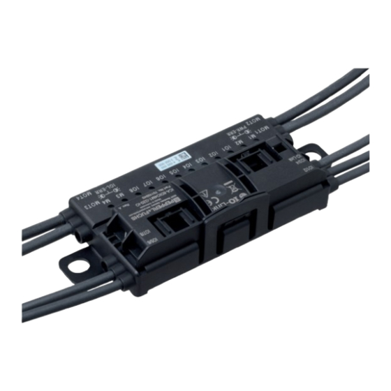
Use and Application General The ICA-8IO-4M4-G20-IO-P14 intelligent motor control module is a field module with eight combined sensor inputs or electronic digital outputs. The four outputs can be used to actuate DC roller motors with operating voltages of 24 V or 48 V. The outputs are optimized for the types: •... - Page 8 ICA-8IO-4M4-G20-IO-P14 Product Description Counters The module has a counter input for connecting an incremental rotary encoder. You can connect a single- or dual-input rotary encoder with a counting frequency of up to 10 kHz. • A single-input rotary encoder is connected to IO1.
-
Page 9: Housing
ICA-8IO-4M4-G20-IO-P14 Product Description General IO-Link Information IO-Link is a standardized point-to-point IO technology (IEC 61131-9) between an IO-Link mas- ter that controls communication and an IO-Link device that acquires or executes process val- ues at the lowest sensor/actuator level. In addition to transmitting process data, IO-Link also provides access to detailed identification, diagnostics, and parameter data of the respective IO- Link device. -
Page 10: Led Indicators
ICA-8IO-4M4-G20-IO-P14 Product Description LED Indicators IO1/2 IO5/6 IO3/4 IO7/8 IO-Link 24V / 48V Power MOT1 MOT3 MOT2 MOT4 PWR-ERR IOL-ERR Figure 2.2 LED Indicators Note The LEDs on the inputs and outputs indicate the physical state of the respective channel. You can find the invertible logical state of a channel in the process data. -
Page 11: Interfaces And Connections
ICA-8IO-4M4-G20-IO-P14 Product Description Note The LEDs MOT1, MOT2, and IO1 to IO8 are supplied from IO-Link; the LEDs MOT3 and MOT4 are supplied from PWR. Note When all LEDs are in the "off" state, a heartbeat (1.9 s off/0.1 s on) is output via all yellow motor LEDs to signal the general operational readiness of the module. -
Page 12: Interface Properties
ICA-8IO-4M4-G20-IO-P14 Product Description Plug Assignment Connection for Connectors Plug type/assignment Inputs/outputs Input: LF004-GS1-A in accordance with IEC/EN 61076-2-104 M8, 4-pin, socket, union nut, A-coded Suitable mating connector: LM004-Gx1-A or simi- 1: V+ sensor supply 2: IO2, IO4, IO6, IO8 3: V- sensor supply... -
Page 13: Braking Energy Power Feedback
ICA-8IO-4M4-G20-IO-P14 Product Description Standard/Extended The module has two different process data structures—standard (STD) and extended (EXT). Which structure is used depends on the IO-Link device ID that is set. While the standard pro- cess data image assigns 8 bytes of input data and 6 bytes of output data, the extended process data image uses 8 bytes of input data and 18 bytes of output data. -
Page 14: Installation
Retain the original packaging in case the device must be stored or shipped again at a later date. Should you have any questions, please contact Pepperl+Fuchs. Mounting Mount the device with both brackets (1) on a solid, continuous surface. - Page 15 ICA-8IO-4M4-G20-IO-P14 Installation Flat-profile cables are narrow on top (with visibly offset profile edge) and wide underneath (pro- file edge not visible). The cable guide allows the flat cables to be inserted on either side, enabling flat cables that are already laid in cable ducts to be connected flexibly. However, it is important to ensure that the profile edge always points toward the motor control module.
- Page 16 ICA-8IO-4M4-G20-IO-P14 Installation Close the cable guide. It must engage securely in the locking bracket (1). The metal piercing pins touch the finely stranded wires in the flat cable. Figure 3.2 Connecting the flat cable on the narrow side Connecting the Flat Cable on the Wide Side The profile edge is not visible from above.
- Page 17 ICA-8IO-4M4-G20-IO-P14 Installation Close the cable guide. It must engage securely in the locking bracket (1). The profile edge (2) of the flat cable is above the two reverse polarity protections. The metal piercing pins touch the finely stranded wires in the flat cable.
-
Page 18: Connecting Motors And Sensors
ICA-8IO-4M4-G20-IO-P14 Installation Flat Cable Inserted Incorrectly The figure below shows an example where the flat cable has been inserted incorrectly. The pro- file edge (2) does not point toward the motor control module, so the flat cable is inserted with reverse polarity. - Page 19 ICA-8IO-4M4-G20-IO-P14 Installation Warning! Damage to contacts Only connect or disconnect the module connections when the module is de–energized. Other- wise, the connections could be damaged.
-
Page 20: Repair And Servicing
ICA-8IO-4M4-G20-IO-P14 Repair and Servicing Repair and Servicing The device must not be repaired, changed, or manipulated. In case of failure, always replace the device with an original device. -
Page 21: Firmware Updates
ICA-8IO-4M4-G20-IO-P14 Firmware Updates Firmware Updates The device supports firmware updates via IO-Link in accordance with the standardized IO-Link firmware update profile IOLFW. The IOLFW files can be found on the detail page for your prod- uct, at www.pepperl-fuchs.com. You can use an IO-Link device tool or other software that supports firmware updates, such as PortVision DX, to perform firmware updates. -
Page 22: Appendix
ICA-8IO-4M4-G20-IO-P14 Appendix Appendix ASCII Table ASCII hex ASCII ASCII hex ASCII Space " & < >... - Page 23 Pepperl+Fuchs Quality Download our latest policy here: www.pepperl-fuchs.com/quality www.pepperl-fuchs.com © Pepperl+Fuchs · Subject to modifications / DOCT-9151...
Need help?
Do you have a question about the ICA-8IO-4M4-G20-IO-P14 and is the answer not in the manual?
Questions and answers