
Related Manuals for Pepperl+Fuchs ICA-16IO-G20-IO-P16


Summary of Contents for Pepperl+Fuchs ICA-16IO-G20-IO-P16
- Page 1 ICA-16IO-G20-IO-P16 G20 IO-Link Module for 16 Freely Configurable Digital Inputs/Outputs Manual...
- Page 2 Phone: +49 621 776 - 0 E-mail: info@de.pepperl-fuchs.com North American Headquarters Pepperl+Fuchs Inc. 1600 Enterprise Parkway Twinsburg, Ohio 44087 Phone: +1 330 425-3555 E-mail: sales@us.pepperl-fuchs.com Asia Headquarters Pepperl+Fuchs Pte. Ltd. P+F Building 18 Ayer Rajah Crescent Singapore 139942 Phone: +65 6779-9091 E-mail: sales@sg.pepperl-fuchs.com https://www.pepperl-fuchs.com...
-
Page 3: Table Of Contents
ICA-16IO-G20-IO-P16 Contents Introduction........................ 4 Content of this Document ................4 Target Group, Personnel ................4 Symbols Used ....................4 General Safety Information................5 Declaration of Conformity................5 Product Description ....................7 Use and Application ..................7 Housing......................7 LED Indicators ....................8 Interfaces and Connections ............... -
Page 4: Introduction
ICA-16IO-G20-IO-P16 Introduction Introduction Content of this Document This document contains information required to use the product in the relevant phases of the product life cycle. This may include information on the following: • Product identification • Delivery, transport, and storage •... -
Page 5: Symbols Used
ICA-16IO-G20-IO-P16 Introduction Symbols Used This document contains symbols for the identification of warning messages and of informative messages. Warning Messages You will find warning messages, whenever dangers may arise from your actions. It is mandatory that you observe these warning messages for your personal safety and in order to avoid prop- erty damage. -
Page 6: Declaration Of Conformity
In the event of any serious errors, stop using the device. Secure the device against unintended operation. To have the device repaired, return it to your local Pepperl+Fuchs representative or your sales center. Note Disposal Electronic waste is dangerous. -
Page 7: Product Description
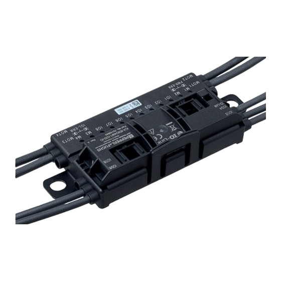
Product Description Product Description Use and Application The ICA-16IO-G20-IO-P16 is an IO-Link field module with 16 freely configurable digital inputs/outputs. The compact housing can be installed directly into support profiles or cable ducts. The module and the inputs and outputs are supplied with power via IO-Link. -
Page 8: Led Indicators
ICA-16IO-G20-IO-P16 Product Description LED Indicators IO7/8 IO9/10 IO5/6 IO11/12 IO-Link IO13/14 IO15/16 Figure 2.2 LED indicators "Left arrow" LED "Right arrow" LED Indication Mode You can select the following modes for the LED indicator: Mode 1: Automatic mode • Alternating indication of bank IO1/2... IO7/8 and bank IO9/10... IO15/16 1<Default ¬¹... - Page 9 ICA-16IO-G20-IO-P16 Product Description "Left arrow" LED The "Left arrow" LED indicates the IO ports IO1/2... IO7/8. The numbers 1... 8 above the LEDs indicate the ports. Status Function The status of ports IO9/10 to IO15/16 is indicated "Right arrow" LED is on...
-
Page 10: Interfaces And Connections
ICA-16IO-G20-IO-P16 Product Description Interfaces and Connections Input/Output Connections The sensors and actuators are connected to the module via cables with round M8 connectors: • Connection: Socket, 4-pin Plug Assignment Connection for connectors Plug type/assignment Inputs/outputs Input: LF004-GS1-A in accordance with... -
Page 11: Installation
Retain the original packaging in case the device must be stored or shipped again at a later date. Should you have any questions, please contact Pepperl+Fuchs. Mounting Mount the device with both brackets (1) on a solid, continuous surface. -
Page 12: Connecting Actuators And Sensors
ICA-16IO-G20-IO-P16 Installation Connecting Actuators and Sensors IO-Link, the inputs, and outputs are connected via standard round plug connectors. IO-Link IO1/2 ... IO15/16 IO1,3 ... 15 IO1... 16 IO2,4 ... 16 n.c. Figure 3.2 Connection wiring diagram Warning! Damage to contacts Only connect or disconnect the module connections when the module is de–energized. -
Page 13: Repair And Servicing
ICA-16IO-G20-IO-P16 Repair and Servicing Repair and Servicing The device must not be repaired, changed, or manipulated. In case of failure, always replace the device with an original device. -
Page 14: Firmware Updates
ICA-16IO-G20-IO-P16 Firmware Updates Firmware Updates The device supports firmware updates via IO-Link in accordance with the standardized IO-Link firmware update profile IOLFW. The IOLFW files can be found on the detail page for your prod- uct, at www.pepperl-fuchs.com. You can use an IO-Link device tool or other software that supports firmware updates, such as PortVision DX, to perform firmware updates. -
Page 15: Appendix
ICA-16IO-G20-IO-P16 Appendix Appendix ASCII table ASCII hex ASCII ASCII hex ASCII Space " & < >... - Page 16 Pepperl+Fuchs Quality Download our latest policy here: www.pepperl-fuchs.com/quality www.pepperl-fuchs.com © Pepperl+Fuchs · Subject to modifications / DOCT-9127...
Need help?
Do you have a question about the ICA-16IO-G20-IO-P16 and is the answer not in the manual?
Questions and answers