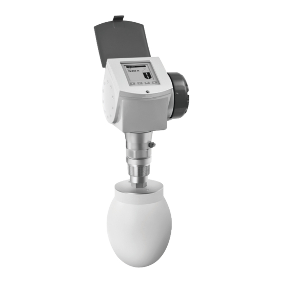
KROHNE OPTIWAVE 6300 C Quick Start Manual
Non-contact radar (fmcw) level meter for solids
Hide thumbs
Also See for OPTIWAVE 6300 C:
- Handbook (128 pages) ,
- Technical data sheet (40 pages) ,
- Supplementary instructions manual (28 pages)
Table of Contents
Advertisement
Quick Links
Advertisement
Table of Contents

Related Manuals for KROHNE OPTIWAVE 6300 C


Summary of Contents for KROHNE OPTIWAVE 6300 C
- Page 1 OPTIWAVE 6300 C OPTIWAVE 6300 C Quick Start Quick Start Quick Start Quick Start Non-contact Radar (FMCW) Level Meter for solids for distance, level, volume and mass measurement of solids © KROHNE 03/2014 - 4000331505 - QS OPTIWAVE 6300 R05 en...
-
Page 2: Table Of Contents
CONTENTS OPTIWAVE 6300 C 1 Safety instructions 2 Installation 2.1 Intended use ........................4 2.2 Scope of delivery....................... 5 2.3 Visual Check ........................6 2.4 Storage ..........................7 2.5 Transport .......................... 8 2.6 Pre-installation requirements ..................8 2.7 How to prepare the silo before you install the device ............. 9 2.7.1 Pressure and temperature ranges.................. -
Page 3: Safety Instructions
SAFETY INSTRUCTIONS OPTIWAVE 6300 C Warnings and symbols used DANGER! This information refers to the immediate danger when working with electricity. DANGER! These warnings must be observed without fail. Even partial disregard of this warning can lead to serious health problems and even death. There is also the risk of seriously damaging the device or parts of the operator's plant. -
Page 4: Installation
INSTALLATION OPTIWAVE 6300 C 2.1 Intended use This radar level transmitter measures distance, level, mass, volume and reflectivity of granulates and powders. It can be installed on silos, hoppers and bunkers. www.krohne.com 03/2014 - 4000331505 - QS OPTIWAVE 6300 R05 en... -
Page 5: Scope Of Delivery
INSTALLATION OPTIWAVE 6300 C 2.2 Scope of delivery INFORMATION! Do a check of the packing list to make sure that you have all the elements given in the order. Scope of delivery – horn antenna Figure 2-1: Scope of delivery – horn antenna... -
Page 6: Visual Check
INSTALLATION OPTIWAVE 6300 C 2.3 Visual Check WARNING! If the display screen glass is broken, do not touch. INFORMATION! Inspect the packaging carefully for damages or signs of rough handling. Report damage to the carrier and to the local office of the manufacturer. -
Page 7: Storage
INSTALLATION OPTIWAVE 6300 C 2.4 Storage WARNING! Do not keep the device in a vertical position. This will damage the antenna and the device will not measure correctly. Figure 2-5: Storage conditions 1 When you put the device into storage, do not keep it in a vertical position 2 Put the device on its side. -
Page 8: Transport
INSTALLATION OPTIWAVE 6300 C 2.5 Transport Figure 2-6: How to lift the device 1 Remove the converter before you lift the device with a hoist. WARNING! Lift the device carefully to prevent damage to the antenna. 2.6 Pre-installation requirements INFORMATION! Obey the precautions that follow to make sure that the device is correctly installed. -
Page 9: How To Prepare The Silo Before You Install The Device
INSTALLATION OPTIWAVE 6300 C 2.7 How to prepare the silo before you install the device CAUTION! To avoid measuring errors and device malfunction, obey these precautions. 2.7.1 Pressure and temperature ranges Figure 2-7: Pressure and temperature ranges 1 Flange temperature ®... -
Page 10: Recommended Mounting Position
INSTALLATION OPTIWAVE 6300 C 2.7.2 Recommended mounting position CAUTION! Follow these recommendations to make sure that the device measures correctly. Figure 2-8: Recommended nozzle position for solids 1 Position of the process fitting from the silo wall, r/2 (for DN80, DN100, DN150 or DN200 horn antennas, and DN80 or... -
Page 11: Installation Recommendations For Solids
INSTALLATION OPTIWAVE 6300 C Figure 2-9: Product inlets 1 The device is in the correct position. 2 The device is too near to the product inlet. Figure 2-10: More than 1 FMCW radar level meter can be operated in a silo More than 1 FMCW radar level meter can be operated in a silo. -
Page 12: How To Install The Device On The Silo
INSTALLATION OPTIWAVE 6300 C Figure 2-11: General installation recommendations 1 The level transmitter can continue to measure to the bottom of the silo if you tilt the device as shown in the illustration (a 2° slanted flange option is available for all antennas) 2 We recommend that you do an empty spectrum recording if there are too many obstacles in the radar beam. -
Page 13: How To Install A Device With A Threaded Connection
INSTALLATION OPTIWAVE 6300 C • Make sure the flange on the nozzle is level. • Make sure that you use the applicable gasket for the flange dimensions and the process. • Align the gasket correctly on the flange facing of the nozzle. -
Page 14: How To Attach Antenna Extensions
INSTALLATION OPTIWAVE 6300 C 2.9.3 How to attach antenna extensions Horn antenna - antenna extensions Figure 2-14: Horn antenna - how to attach antenna extensions Equipment needed: • 3 mm Allen wrench (not supplied) For more data, refer to the handbook. -
Page 15: How To Turn Or Remove The Signal Converter
INSTALLATION OPTIWAVE 6300 C 2.9.4 How to turn or remove the signal converter INFORMATION! The converter turns 360 . The converter can be removed from the process connection assembly ° under process conditions. Figure 2-16: How to turn or remove the signal converter... -
Page 16: How To Attach The Weather Protection To The Device
INSTALLATION OPTIWAVE 6300 C 2.9.5 How to attach the weather protection to the device Equipment needed: • Device. • Weather protection (option). • 10 mm wrench (not supplied). The overall dimensions of the weather protection are in "Dimensions and weight" in the handbook. -
Page 17: How To Open The Weather Protection
INSTALLATION OPTIWAVE 6300 C 2.9.6 How to open the weather protection Equipment needed: • Weather protection attached to the device. • Large slotted tip screwdriver (not supplied). Figure 2-18: How to open the weather protection 1 Weather protection in its closed position 2 Weather protection in its open position. -
Page 18: Electrical Connections
ELECTRICAL CONNECTIONS OPTIWAVE 6300 C 3.1 Safety instructions DANGER! All work on the electrical connections may only be carried out with the power disconnected. Take note of the voltage data on the nameplate! DANGER! Observe the national regulations for electrical installations! DANGER! For devices used in hazardous areas, additional safety notes apply;... -
Page 19: Non-Ex Devices
ELECTRICAL CONNECTIONS OPTIWAVE 6300 C Procedure: • Remove the housing terminal compartment cover 1. • Connect the wires to the device. Obey the national electrical codes. • Make sure that the polarity of the wires is correct. • Attach the ground to 4 or 7. Both terminals are technically equivalent. -
Page 20: Protection Category
ELECTRICAL CONNECTIONS OPTIWAVE 6300 C 3.3 Protection category INFORMATION! The device fulfils all requirements per protection category IP 66/67. It also fulfils all requirements per NEMA type 4X (housing) and type 6P (antenna). DANGER! Make sure that the cable gland is watertight. -
Page 21: Technical Data
TECHNICAL DATA OPTIWAVE 6300 C 4.1 Technical data INFORMATION! • The following data is provided for general applications. If you require data that is more relevant to your specific application, please contact us or your local sales office. Additional information (certificates, special tools, software,...) and complete product •... - Page 22 TECHNICAL DATA OPTIWAVE 6300 C Measurement accuracy Resolution 1 mm / 0.04¨ Repeatability ±1 mm / ±0.04¨ Accuracy ±3 mm / ±0.12¨, when distance < 10 m / 33 ft; ±0.03% of measured distance, when distance > 10 m / 33 ft Reference conditions acc.
- Page 23 TECHNICAL DATA OPTIWAVE 6300 C Installation conditions Process connection size The nominal diameter (DN) should be equal to or larger than the antenna diameter. If the nominal diameter (DN) is smaller than the antenna, either: – provide the means to adapt the device to a larger process connection on the silo (for example, a plate with a slot), or –...
- Page 24 TECHNICAL DATA OPTIWAVE 6300 C Electrical connections Terminals output 1 – Non-Ex / Ex i: Power supply Terminals output 1 Terminals output 1 Terminals output 1 Non-Ex / Ex i: Non-Ex / Ex i: Non-Ex / Ex i: 14…30 VDC; min./max. value for an output of 22 mA at the terminal Terminals output 1 Terminals output 1 –...
- Page 25 TECHNICAL DATA OPTIWAVE 6300 C CSA – Dual Seal-approved CEC Section 18 (Zone ratings) CEC Section 18 (Zone ratings) CEC Section 18 (Zone ratings) CEC Section 18 (Zone ratings) Cl. I, Zone 1, Ex d, IIC (Antenna: Zone 0) T6;...
-
Page 26: Notes
NOTES OPTIWAVE 6300 C www.krohne.com 03/2014 - 4000331505 - QS OPTIWAVE 6300 R05 en... - Page 27 NOTES OPTIWAVE 6300 C 03/2014 - 4000331505 - QS OPTIWAVE 6300 R05 en www.krohne.com...
- Page 28 Measuring systems for the marine industry Head Office KROHNE Messtechnik GmbH Ludwig-Krohne-Str. 5 47058 Duisburg (Germany) Tel.:+49 203 301 0 Fax:+49 203 301 103 89 info@krohne.com The current list of all KROHNE contacts and addresses can be found at: www.krohne.com...
Need help?
Do you have a question about the OPTIWAVE 6300 C and is the answer not in the manual?
Questions and answers