KROHNE OPTISONIC 6300 Quick Start
Ultrasonic clamp-on c
Hide thumbs
Also See for OPTISONIC 6300:
- Handbook (212 pages) ,
- Manual (60 pages) ,
- Quick start manual (56 pages)
Advertisement
Quick Start
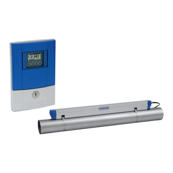
OPTISONIC 6300
Ultrasonic clamp-on flowmeter
Installation, assembly, start-up and maintenance may only be performed by appropriately trained
personnel.
For use in hazardous areas, special codes and regulations are applicable which are supplied in a
separate document that describes all hazardous area relevant information.
The responsibility as to the suitability, intended use and corrosion resistance of the used materials
against the measured fluid of this device rests solely with the operator.
For complete documentation (manuals, supplementary manuals, data sheets and certificates) please
refer to:
www.krohne.com/Downloads
Diameter range and rail versions
Small
DN15...100 / 0.5...4"
Small
Medium
DN50...400 / 2...16"
Preferred measuring modes
10/2020 - 4007758002 - OPTISONIC 6300 R02 en
General
System Configuration
1 Electrical connection
Medium
DN200...1250 / 8...50"
Large
DN200...4000 / 8...160"
For initial set up, we strongly recommend the use of the relevant manuals in addition!
Check the device nameplate to ensure that the device is
delivered according to your order.
All work on the electrical connections may only be carried out with the power disconnected.
Take note of the voltage data on the nameplate! Observe the national regulations for electrical installations!
Observe without fail the local occupational health and safety regulations.
Any work done on the electrical components of the measuring device may only be carried out by properly
trained specialists.
Electrical connections signal converter
2 3
1
1
2
Device nameplate
Power supply - grounding
3
2
100...230VAC (-15% / +10%), 22VA
24VDC (-55% / +30%), 12W
24VAC/DC (AC: -15% / +10%; DC: -25% / +30%),
22VA or 12W
The device must be grounded in accordance with
regulations in order to protect personnel against
electric shocks.
3
For devices used in hazardous areas, additional
safety notes apply; please refer to the Ex
documentation.
Refer to the manual for connection of Ex (/i ) acc. to
NAMUR
1
Sensor cable connections
2
I/O connections
3
Mains supply connection
1
Advertisement
Table of Contents

Related Manuals for KROHNE OPTISONIC 6300


Summary of Contents for KROHNE OPTISONIC 6300
- Page 1 Large Refer to the manual for connection of Ex (/i ) acc. to Medium NAMUR DN50...400 / 2...16" DN200...4000 / 8...160" Sensor cable connections I/O connections Preferred measuring modes Mains supply connection 10/2020 - 4007758002 - OPTISONIC 6300 R02 en...
- Page 2 ≥ 20 × ∅ 120 ° Installation position Pump, control valve - open feed / discharge Check the OPTISONIC 6300 manual for more details on installation options (e.g. Large version installation) * Change the position of the transducer General configuration instructions Go through menu X1...X5...
- Page 3 A6 GDC IR interface X9.6 Tc calibration no. ↑ ↓ ↑ ↓ ↑ ↓ ↑ ↓ ↑ ↓ ↑ ↓ ↑ ↓ ↑ ↓ 1 shows when configuring a 2 pipe installation 10/2020 - 4007758002 - OPTISONIC 6300 R02 en...
- Page 4 Control input active Ca, (modular I/O) Contact Current output passive Ip (modular/Ex i I/O) Control input passive Cp, (modular/Ex i I/O) To view all KROHNE locations and contact details visit: www.krohne.com Control input active CN to NAMUR, (modular I/O) Pulse/frequency output active Pa (modular I/O) Then “Select your country“...
Need help?
Do you have a question about the OPTISONIC 6300 and is the answer not in the manual?
Questions and answers