Table of Contents
Advertisement
Quick Links
Advertisement
Table of Contents

Related Manuals for CET PMC-53M-E


Summary of Contents for CET PMC-53M-E
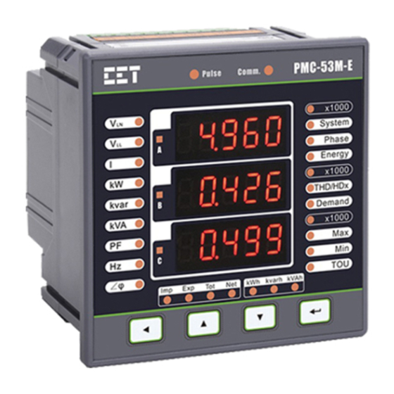
- Page 1 PMC-53M-E Digital Multifunction Meter User Manual Version: V1.1A July 6, 2021...
- Page 2 The information contained in this manual is believed to be accurate at the time of publication; however, CET assumes no responsibility for any errors which may appear here and reserves the right to make changes without notice. Please consult CET or your local representative for the latest product specifications.
- Page 3 CET Electric Technology DANGER Failure to observe the following instructions may result in severe injury or death and/or equipment damage. ➢ Installation, operation and maintenance of the meter should only be performed by qualified, competent personnel that have the appropriate training and experience with high voltage and current devices.
- Page 4 This warranty is on a return to factory for repair basis. ➢ CET does not accept liability for any damage caused by meter malfunctions. CET accepts no responsibility for the suitability of the meter to the application for which it was purchased.
-
Page 5: Table Of Contents
Table of Contents Chapter 1 Introduction ..........................7 1.1 Overview ............................ 7 1.2 Features ............................7 1.3 PMC-53M-E application in Power and Energy Management Systems ........9 1.4 Getting more information ......................9 Chapter 2 Installation ..........................10 2.1 Appearance ..........................10 2.2 Unit Dimensions ........................ - Page 6 CET Electric Technology 4.5.2 Max. Demand Log ......................36 4.5.3 SOE Log ......................... 36 4.6 Diagnostics ..........................36 Chapter 5 Modbus Register Map ......................38 5.1 Basic Measurements ........................ 38 5.2 Energy Measurements ......................40 5.2.1 3-Phase Total Energy Measurements ................40 5.2.2 Phase A (L1) Energy Measurements ................
-
Page 7: Chapter 1 Introduction
This manual explains how to use the PMC-53M-E Digital Multifunction Meter. Throughout the manual the term “meter” generally refers to all models. This chapter provides an overview of the PMC-53M-E meter and summarizes many of its key features. 1.1 Overview The PMC-53M-E Digital Multifunction Meter is CET’s latest offer for the low-cost digital power/energy... - Page 8 ▪ Equipped with a battery-backed Real-Time Clock with 25ppm accuracy (<2s per day) System Integration ▪ Supported by CET’s PecStar® iEMS and iEEM ▪ Easy integration into 3 -party Energy Management, Automation or SCADA or BMS systems via Modbus RTU...
-
Page 9: Pmc-53M-E Application In Power And Energy Management Systems
CET Electric Technology 1.3 PMC-53M-E application in Power and Energy Management Systems The PMC-53M-E can be used to monitor Wye or Delta connected power system. Modbus communications allow real-time data, DI status and other information to be transmitted across a RS485 network to an Integrated Energy Management system such as PecStar®. -
Page 10: Chapter 2 Installation
Chapter 2 Installation Caution Installation of the PMC-53M-E should only be performed by qualified and competent personnel who have the appropriate training and experience with high voltage and current devices. The meter must be installed in accordance with all local and national electrical codes. -
Page 11: Unit Dimensions
(14AWG - 22AWG) (12 lb-in) Table 2-1 Terminal Dimensions 2.4 Mounting The PMC-53M-E should be installed in a dry environment with no dust and kept away from heat, radiation and electrical noise source. Installation steps: ▪ Remove the installation clips from the meter ▪... -
Page 12: Wiring Connections
Figure 2-4 Panel Cutout Mounting 2.5 Wiring connections PMC-53M-E can satisfy almost any three phase power systems. Please read this section carefully before installation and choose the correct wiring method for your power system. The following Wiring Modes are supported: ▪... -
Page 13: 3-Phase 4-Wire (3P4W) Wye Direct Connection With 3Cts
CET Electric Technology 2.5.1 3-Phase 4-Wire (3P4W) Wye Direct Connection with 3CTs Please consult the serial number label to ensure that the rated system phase voltage is less than or equal to the meter’s rated phase voltage input specification. Set the Wiring Mode to 3P4W. -
Page 14: 3-Phase 3-Wire (3P3W) Direct Delta Connection With 3Cts
CET Electric Technology 2.5.3 3-Phase 3-Wire (3P3W) Direct Delta Connection with 3CTs Please consult the serial number label to ensure that the rated system line voltage is less than or equal the meter’s specification rated line voltage input . Set the Wiring Mode to 3P3W. -
Page 15: 3-Phase 3-Wire (3P3W) Delta With 2Pts And 3Cts
CET Electric Technology 2.5.5 3-Phase 3-Wire (3P3W) Delta with 2PTs and 3CTs Please consult the serial number label to ensure that the rated PT secondary voltage is less than or equal to the meter’s rated phase voltage input specification. Set the Wiring Mode to 3P3W. -
Page 16: 1-Phase 3-Wire (1P3W) Direct Connection With 2Cts
CET Electric Technology 2.5.7 1-Phase 3-Wire (1P3W) Direct Connection with 2CTs Please consult the Serial Number Label to ensure that the rated system phase voltage is less than or equal to the meter’s rated phase voltage input specification. Set the Wiring Mode to 1P3W. -
Page 17: 1-Phase 2-Wire, Ull (1P2W-Ull) Direct Connection With 1Ct
The following figure illustrates the RS-485 communications connections on the PMC-53M-E: Figure 2-14 Communications Connections The PMC-53M-E provides one standard RS-485 port which supports the Modbus RTU protocol. Up to 32 devices can be connected on a RS-485 bus. The overall length of the RS-485 cable connecting all devices should not exceed 1200m. -
Page 18: Digital Input Wiring
CET Electric Technology 2.7 Digital Input Wiring The following figure illustrates the Digital Input connections on the PMC-53M-E: Figure 2-15 DI Connections 2.8 Digital Output Wiring The following figure illustrates the Digital Output connections on the PMC-53M-E: Figure 2-16 DO Connections 2.9 Power Supply Wiring... -
Page 19: Chapter 3 Front Panel
CET Electric Technology Chapter 3 Front Panel The PMC-53M-E has a High-contrast LED display with four buttons for data display and meter configuration. This chapter introduces the front panel operations. Figure 3-1 Front Panel 3.1 Display 3.1.1 LED Testing Pressing and holding both the < > and the < > buttons simultaneously enters the LED Testing mode. -
Page 20: Using The Front Panel Buttons
CET Electric Technology 3.2 Using the Front Panel Buttons The button definitions under Display Mode and Setup Mode are explained in the following table. The default password is 0. Buttons Data Display Mode Setup Configuration Mode • Before parameter selected... -
Page 21: System
CET Electric Technology 3.3.1 System Figure 3-2 provides an example for the default Display Screen, and Table 3-3 illustrates all the Display Screens under the <System> menu. Figure 3-2 System Display Example Menu Display Screens Display 1 (Default) I avg... -
Page 22: Energy
CET Electric Technology Display 3 1,2,3 Display 4 1,2,3 Display 5 kvara kvarb kvarc 1,2,3 Display 6 kVAa kVAb kVAc 1,2,3 Display 7 2,3,4 Display 8 Ua Angle Ub Angle Uc Angle Display 9 Ia Angle Ib Angle Ic Angle... -
Page 23: Demand
CET Electric Technology Figure 3-5 THD/HDx Display Example Menu Display Screens Display 1 Display 2 TOHD Display 3 TEHD <Ua/Uab> Display 4 HD02 Display 5~32 … Display 33 HD31 Display 1 Display 2 TOHD Display 3 TEHD <Ub/Ubc> Display 4... -
Page 24: Max./Min
CET Electric Technology Figure 3-6 Demand Display Example Menu Display Screens Display 1 Display 2 Display 3 Display 4 Display 5 kvar Display 6 <Demand> Display 1 Display 2 Display 3 <Max> Display 4 Display 5 kvar Display 6 Table 3-7 Demand Display... -
Page 25: Setup Configuration Via The Front Panel
CET Electric Technology Display 10 Display 11 Display 12 I avg Display 13 Display 14 Display 15 Display 16 kW Total Display 17 kvara Display 18 kvarb Display 19 kvarc Display 20 kvar Total Display 21 kVAa Display 22 kVAb... -
Page 26: Setup Menu
CET Electric Technology 3.4.2 Setup Menu Figure 3-2 Setup Menu... -
Page 27: Configuration
CET Electric Technology 3.4.3 Configuration The Setup Configuration mode provides access to the following setup parameters: Label Parameters Description Range Default Menu Main PROG Programming Setup Configuration PASS Password Enter Password 0 to 9999 Enter Sub Menu to change PASS SET... - Page 28 CET Electric Technology Clear Max./Min. Log of This MA/MN Max./Min. Logs YES/NO Month (Since Last Reset) RUN TIM Run Time Clear Device Operating Time YES/NO PULSE DI Counter Clear DI Counters YES/NO Clear SOE logs YES/NO ALL DATA All data...
- Page 29 CET Electric Technology Figure 3-3 P.F. Convention 3) There are two ways to calculate kVA: Mode V (Vector method): Mode S (Scalar method): 4) There are two ways to calculate THD: THDf (based on Fundamental): where I represents the RMS value for the n...
-
Page 30: Chapter 4 Applications
Please refer to Section 4.4 for a detailed description. Since there are multiple ways to trigger the Digital Outputs on the PMC-53M-E, a prioritized scheme has been developed to avoid conflicts between different applications. In general, Front Panel Control has the highest priority and can override other control schemes. -
Page 31: Power And Energy
Ia, Ib, Ic, kW Total, kvar Total and kVA Total. Predicted Demand is typically used for pre-alarming and to help users reduce power consumption using a Setpoint to warn that the Demand limit may be exceeded. The PMC-53M-E provides the following setup parameters which can be programmed via the Front Panel or via communication:... -
Page 32: Power Quality
The PMC-53M-E provides the following PQ parameters: 4.3.2.1 Harmonics The PMC-53M-E provides harmonic analysis for THD, TOHD, TEHD and individual harmonics up to the order. All harmonic parameters are available on the front panel and through communications. In addition, the PMC-53M-E also provides TDD, K-factor and Crest-factor measurements for current. -
Page 33: Setpoints
The Voltage and Current Unbalance measurements are only available via communications. 4.4 Setpoints The PMC-53M-E comes standard with 9 user programmable setpoints which provide extensive control by allowing a user to initiate an action in response to a specific condition. Typical setpoint applications... - Page 34 CET Electric Technology Figure 4-1 Over Setpoint Figure 4-2 Under Setpoint Setpoints can be programmed via the Front Panel or through communications and have the following setup parameters: Setup Parameter Definition Options/Default* 0=Disabled* Setpoint Type Disabled, Over or Under Setpoint.
-
Page 35: Logging
4.5 Logging 4.5.1 Max./Min. Log The PMC-53M-E records the Max. Log and Min. Log of This Month (Since Last Reset) and Last Month (Before Last Reset) with timestamp for 44 parameters. Each log includes the relevant parameter value and its timestamp. The recorded data is stored in non-volatile memory and will not suffer any loss in the event of a power failure. -
Page 36: Max. Demand Log
Table 4-10 Max. Demand Log 4.5.3 SOE Log The PMC-53M-E’s SOE Log can store up to 64 events such as Power-on, Power-off, Digital Input status changes, Digital Output status changes, Setup changes and Setpoint events in its non-volatile memory. Each event record includes the event classification, its relevant parameter values and a timestamp in ±1 ms resolution. - Page 37 CET Electric Technology Negative kWa may be abnormal (3P4W only) Negative kWb may be abnormal (3P4W only) Negative kWc may be abnormal (3P4W only) CTa polarity may be reversed (3P4W only) CTb polarity may be reversed (3P4W only) CTc polarity may be reversed (3P4W only)
-
Page 38: Chapter 5 Modbus Register Map
2) Force Single Coil (Function Code 0x05) 3) Preset Multiple Registers (Function Code 0x10) The following table provides a description of the different data formats used for the Modbus registers. The PMC-53M-E uses the Big Endian byte ordering system. Format Description... - Page 39 Table 5-3 Wiring Diagnostic Status Register 6) The PMC-53M-E has one SOE Log. The SOE log has a Log Pointer that indicates its current logging position. The range of the Log Pointer is between 0 and 0xFFFFFFFF, and it is incremented by one for every new log generated and will roll over to 0 if its current value is 0xFFFFFFFF.
-
Page 40: Energy Measurements
CET Electric Technology 5.2 Energy Measurements The Energy registers have a maximum value of 1,000,000,000 and will roll over to zero automatically when it is reached. The actual energy value is 0.1 times of the register value. 5.2.1 3-Phase Total Energy Measurements... -
Page 41: Di Pulse Counters (Optional)
CET Electric Technology 0870 kvarh Export INT32 0872 kvarh Net INT32 0874 kvarh Total INT32 0876 kVAh INT32 kVAh 0878 kvarh Q1 INT32 0880 kvarh Q2 INT32 kvarh 0882 kvarh Q3 INT32 0884 kvarh Q4 INT32 Table 5-7 Phase C Energy Measurements 5.3 DI Pulse Counters (Optional) -
Page 42: Voltage Harmonic Measurements
CET Electric Technology 1592 Ia HD31 Float 1594 Ib HD31 Float 1596 Ic HD31 Float Table 5-10 Current Harmonic Measurements Notes: 1) When the Wiring Mode is 1P2W L-N or 1P2W L-L, the Ib/Ic THD/TOHD/TEHD/HDxx have no meaning, and their registers are reserved. -
Page 43: Max. Demand Log Of This Month (Since Last Reset)
CET Electric Technology 3204 Float 3206 kW Total Float 3208 kvar Total Float 3210 kVA Total Float Table 5-13 Predicted Demand Measurements Notes: 1) When the Wiring Mode is 1P2W L-N or 1P2W L-L, the Ib/Ic Predicted Demand have no meaning, and their registers are reserved. -
Page 44: Min. Log Of This Month (Since Last Reset)
CET Electric Technology 4006~4011 Max./Min. Log Structure 4012~4017 4018~4023 Uln Average 4024~4029 4030~4035 4036~4041 4042~4047 Ull Average 4048~4053 4054~4059 4060~4065 4066~4071 I Average 4072~4077 4078~4083 4084~4089 4090~4095 kW Total 4096~4101 kvara 4102~4107 kvarb 4108~4113 kvarc 4114~4119 kvar Total 4120~4125 kVAa... -
Page 45: Max. Log Of Last Month (Before Last Reset)
CET Electric Technology 4366~4371 I Average 4372~4377 4378~4383 4384~4389 4390~4395 kW Total 4396~4401 kvara 4402~4407 kvarb 4408~4413 kvarc 4414~4419 kvar Total 4420~4425 kVAa 4426~4431 kVAb 4432~4437 kVAc 4438~4443 kVA Total 4444~4449 4450~4455 4456~4461 4462~4467 PF Total 4468~4473 Frequency 4474~4479 In (Calculated) -
Page 46: Min. Log Of Last Month (Before Last Reset)
CET Electric Technology 4726~4731 kVAb 4732~4737 kVAc 4738~4743 kVA Total 4744~4749 4750~4755 4756~4761 4762~4767 PF Total 4768~4773 Frequency 4774~4779 In (Calculated) 4780~4785 Uan/Uab THD 4786~4791 Ubn/Ubc THD 4792~4797 Ucn/Uca THD 4798~4803 Ia THD 4804~4809 Ib THD 4810~4815 Ic THD 4816~4821... -
Page 47: Max./Min. Log Structure
CET Electric Technology 5086~5091 Ubn/Ubc THD 5092~5097 Ucn/Uca THD 5098~5103 Ia THD 5104~5109 Ib THD 5110~5115 Ic THD 5116~5121 Ia K-factor 5122~5127 Ib K-factor 5128~5133 Ic K-factor 5134~5139 Ia Crest-factor 5140~5145 Ib Crest-factor 5146~5151 Ic Crest-factor 5152~5157 Voltage Unbalance 5158~5163 Current Unbalance Table 5-20 Min. - Page 48 CET Electric Technology Record Time: Day 1 to 31 Record Time: Hour 0 to 23 Record Time: Minute 0 to 59 Record Time: Second 0 to 59 Record Time: Millisecond 0 to 999 High-order Byte: Reserved Low-order Byte: Status +6 to +7...
- Page 49 CET Electric Technology 1 / 0 Under kvar Total Setpoint Active/Return 1 / 0 Under kVA Total Setpoint Active/Return 1 / 0 Under PF Total Setpoint Active/Return Under kW Total Present Demand Setpoint 1 / 0 Active/Return Under kvar Total Present Demand Setpoint...
-
Page 50: Device Setup
CET Electric Technology Setup Changes via Communication Preset Energy Value via Communication Table 5-24 SOE Event Classification 3) Clear All Data via Front Panel or Communication means to clear 3-Phase Total Energy registers, Phase A/B/C Energy registers, All Max. Demands, All Max./Min. Logs, Device Operating Time, SOE Log and All DI Pulse Counters. -
Page 51: I/O Setup (Optional)
0 to 6000 (x0.1s), 10* 6237 DO2 Pulse Width UINT16 (0 = Latch Mode) Table 5-26 I/O Setup Parameters Notes: 1) The DI/DO Setup registers are available only when the PMC-53M-E is equipped corresponding options. 5.8.3 Communication Setup Parameters Register Property Description Format... -
Page 52: Time
5.9 Time There are two sets of Time registers supported by the PMC-53M-E – Year / Month / Day / Hour / Minute / Second (Registers # 60000 to 60002) and UNIX Time (Register # 60004). When sending time to the PMC-53M-E over Modbus communications, care should be taken to only write one of the two Time register sets. -
Page 53: Remote Control
Only”. The DO Status register 0098 should be read instead to determine the current DO status. The PMC-53M-E adopts the ARM before EXECUTE operation for the remote control of its Digital Outputs if this function is enabled through the Arm Before Execute Enable Setup register (6032), which is disabled by default. -
Page 54: Meter Information
Bit 8 to Bit 15: Reserved Table 5-34 Meter Information Notes: 1) The Meter Model appears from registers 60200 to 60219 and contains the ASCII encoding of the string “PMC-53M-E” as shown in the following table. Register Value(Hex) ASCII 60200... -
Page 55: Appendix A Technical Specifications
CET Electric Technology Appendix A Technical Specifications Voltage Inputs (V1, V2, V3, VN) 400ULN/690ULL* Range 10V to 1.2xUn Overload 1.2xUn continuous, 2xUn for 1s Burden <0.02VA per phase Measurement Category CAT III up to 600VLL Frequency 45-65Hz Current Inputs (I11, I12, I21, I22, I31, I32) -
Page 56: Appendix B Standards Compliance
CET Electric Technology Appendix B Standards Compliance Safety Requirements CE LVD 2014 / 35 / EU EN61010-1: 2010, EN61010-2-030: 2010 UL 61010-1 Ed. 3 cULus Listed CAN/CSA C22.2 NO. 61010-1-12 Ed. 3 UL 61010-2-030 Ed. 2 CSA C22.2 NO. 61010-2-030: 18 Ed. 2 UL 61010-2-201 Ed. -
Page 57: Appendix C Maintenance
CET Electric Technology Appendix C Maintenance Overview Caution Do not open the meter case. Do not attempt to repair any components of the meter. Failure to follow these instructions can result in equipment damage. The meter does not contain any user-serviceable parts. If the meter requires service, contact your local representative. - Page 58 Select whether to create a desktop icon and click Next to continue. Click Install to start the installation. Click Finish to complete the installation Use the Serial to USB line to connect the PMC-53M-E’s COM Port with PC. Double click the desktop icon to open the PMC-Upgrader and select Serial connection.
- Page 59 Click to choose the firmware upgraded package. After clicking Upgrade, the connection with the PMC-53M-E will be established and then the parameters backup will be processed automatically. The entire firmware upgrade process may take about two minutes, please do not...
- Page 60 CET Electric Technology Press < > for two seconds to enter Setup Configuration mode, and the LED displays PROG. Press < > advance to the Password page. Press < > or < > to scroll through the list of sub-menus Press <...
-
Page 61: Appendix D Ordering Guide
CET Electric Technology Appendix D Ordering Guide... -
Page 62: Contact Us
CET Electric Technology Contact us CET Electric Technology Inc. Email: support@cet-global.com Web: www.cet-global.com...
Need help?
Do you have a question about the PMC-53M-E and is the answer not in the manual?
Questions and answers