Table of Contents
Advertisement
Quick Links
Advertisement
Table of Contents

Related Manuals for CET PMC-592


Summary of Contents for CET PMC-592
- Page 1 PMC-592 Multi Circuit Power Monitor User Manual Version: V1.1 November 21, 2018...
- Page 2 The information contained in this Manual is believed to be accurate at the time of publication; however, CET assumes no responsibility for any errors which may appear here and reserves the right to make changes without notice. Please consult CET or your local representative for latest product specifications.
- Page 3 CET Electric Technology DANGER Failure to observe the following instructions may result in severe injury or death and/or equipment damage. Installation, operation and maintenance of the meter should only be performed by qualified, competent personnel that have the appropriate training and experience with high voltage and current devices.
- Page 4 This warranty is on a return to factory for repair basis. CET does not accept liability for any damage caused by meter malfunctions. CET accepts no responsibility for the suitability of the meter to the application for which it was purchased.
-
Page 5: Table Of Contents
2.5.1 Ethernet Port (10/100BaseT) ..................42 2.5.2 P1/HMI (RS485/RS422/RS232) Wiring ................42 2.5.3 P2 (RS485) Wiring ......................43 2.5.4 PMC-592 External DI Module Wiring ................43 2.6 Digital Input Wiring ........................44 2.7 Digital Output Wiring ....................... 44 2.8 RTD Input Wiring ........................44 2.9 Main Unit Power Supply Wiring .................... - Page 6 3.2 Web Interface ........................... 46 3.2.1 Setting PC's IP Address ....................46 3.2.2 Configure PMC-592's IP Address using the Touch-Screen HMI ........47 3.2.3 Accessing PMC-592’s Web Interface via Mobile Devices ..........47 3.2.4 Accessing PMC-592’s Web Interface ................48 3.3 HMI Display (Optional) ......................
- Page 7 CET Electric Technology 4.7.4 Waveform Recorder (WFR) ..................104 4.7.5 Data Recorder (DR) ..................... 105 4.8 Communications ........................106 4.8.1 Modbus TCP ........................ 106 4.8.2 HTTP ..........................106 4.8.3 SNMP (Simple Network Management Protocol) ............106 4.8.4 SNTP (Simple Network Time protocol)................ 110 4.8.5 SMTP (Simple Mail Transfer Protocol) .................
- Page 8 Appendix D - Accuracy Specifications ....................165 Appendix E - Standards Compliance ..................... 166 Appendix F – Firmware Upgrade ......................167 Appendix G - PMC-592 Firmware and HMI Version Compatibility ............171 Appendix H - FAQ ..........................172 Contact us ............................. 176...
-
Page 9: Glossary
CET Electric Technology Glossary = Automatic Transfer Switch = CET Electric Technology = Digital Input = Present Demand = Digital Output FIFO = First In First Out Fund. = Fundamental = Giga Byte = Human Machine Interface = nth order Harmonic, integer multiple (n) of the Fundamental Frequency (50Hz or 60Hz) -
Page 10: Chapter 1 Introduction
This chapter provides an overview of the PMC-592 and summarizes many of its key features. 1.1 Overview The PMC-592 MCPM is the ultimate solution for PDU, LVDB and Load Center application that require multi circuit monitoring. Housed in a compact metal enclosure, the PMC-592 is perfectly suited for applications that require high density metering. - Page 11 CET Electric Technology Flexible Configuration Programmable CT Ratio, CT Polarity, Sub-Meter (SM) Reference Voltage for each SM Configurable CT Strip Orientation (Sequential or Crossover) and CT Strip Direction (Top or Bottom) Configurable 2-Ø & 3-Ø SM Ordering based on out-of-sequence 1-Ø SM ...
- Page 12 Digital Inputs 2 standard or 4 optional* DI channels, volts free dry contact, 24VDC internally wetted Support up to 4 External DI Modules from CET (e.g. PMC-521D) via Port 2 (RS-485) 1000Hz sampling for status monitoring with programmable debounce...
-
Page 13: Getting More Information
Time Synchronization via SNTP protocol System Integration PecStar iEMS The PMC-592 is supported by CET’s PecStar iEMS. It can also be easily integrated into other 3rd party systems with its support of multiple communications ports and different industry standard protocols. Party System Integration ... -
Page 14: Chapter 2 Installation
Chapter 2 Installation Caution Installation of the PMC-592 should only be performed by qualified, competent personnel that have the appropriate training and experience with high voltage and current devices. The device must be installed in accordance with all local and national electrical codes. -
Page 15: Hmi And Lcd Display (Optional)
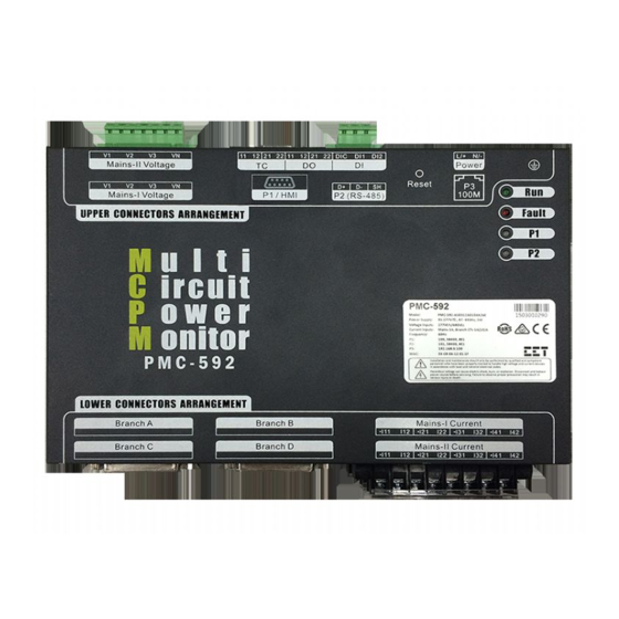
CET Electric Technology Figure 2-4 Lower Connector’s Arrangement 2.1.2 HMI and LCD Display (Optional) Figure 2-5 7” Touch Screen HMI and Basic LCD Display 2.1.3 Accessories Branch SCCT Adapter Board CT Strips Figure 2-6 CT Strips and Branch SCCT Adapter Board... -
Page 16: Dimensions
CET Electric Technology 2.2 Dimensions 2.2.1 Main Unit Front View Side View Figure 2-9 Main Unit Dimensions 2.2.2 HMI (Optional) The following sections provide dimensions for the three HMI models: TK6070iH, TK6070iQ and TK6071iQ. 2.2.2.1 TK6070iH Figure 2-10 TK6070iH Dimensions... -
Page 17: 21-Ct Strip With ¾ " Spacing
CET Electric Technology 2.2.2.2 TK6070iQ and TK6071iQ Figure 2-11 TK6070iQ and TK6071iQ Dimensions 2.2.3 21-CT Strip with ¾ " Spacing Top View Side View ¾ Figure 2-12 Dimensions of the 21 CT Strip with ” Spacing 2.2.4 21-CT Strip with 1" Spacing... -
Page 18: 12-Ct Strip With ¾ " Spacing
CET Electric Technology 2.2.5 12-CT Strip with ¾ " Spacing Top View Side View Figure 2-14 Dimensions of the 12-CT Strip with ¾ " Spacing 2.2.6 CT Strip’s Solid-Core CT Figure 2-15 Dimensions of the CT Strip’s Solid-Core CT 2.2.7 SCCT Adapter Board... -
Page 19: Mains Scct
CET Electric Technology 2.2.8 Mains SCCT Figure 2-17 Mains SCCT Dimensions There are four Mains SCCT models: PMC-SCCT-400A-1A-A, PMC-SCCT-600A-1A-A, PMC-SCCT-800A-1A- A and PMC-SCCT-1000A-1A-A. The dimensions are described below. Mode PMC-SCCT-400A-1A-A 52.5 67.5 PMC-SCCT-600A-1A-A 52.5 67.5 PMC-SCCT-800A-1A-A 52.5 67.5 PMC-SCCT-1000A-1A-A 52.5 67.5... - Page 20 CET Electric Technology 2.2.9.2 200A/40mA SCCT Figure 2-19 Dimensions of 200A/40mA SCCT 2.2.9.3 400A/40mA SCCT Figure 2-20 Dimensions of 400A/40mA SCCT 2.2.9.4 800A/40mA SCCT Figure 2-21 Dimensions of 800A/40mA SCCT...
-
Page 21: Mounting
CET Electric Technology 2.3 Mounting The PMC-592 should be installed in a dry environment without dust and kept away from heat, radiation and electrical noise sources. The PMC-592 is usually installed inside the PDU cabinet. Please reserve enough room for other accessories and make it convenient for future maintenance. - Page 22 CET Electric Technology CT Strip Type Surface Mounting Diagram 21-CT Strip with ¾ " spacing between CTs 21-CT Strip with 1" spacing between CTs 12-CT Strip with ¾ " spacing between CTs Table 2-2 Surface Mounting of CT Strip DIN-Rail Mounting ...
- Page 23 CET Electric Technology 21 CTs Strip with 1" spacing between 12 CTs Strip with ¾ " spacing between Table 2-3 DIN-Rail Mounting of CT Strip 2.3.2.2 Mounting the Branch SCCT Adapter Board Surface Mounting Pre-drill the mounting holes based on the mounting diagrams below.
- Page 24 1. If SCCTs are used for the Mains Current Inputs, please ensure to select the 1A Mains Current Input option for the PMC-592. Before installing the Mains SCCTs, please ensure that SCCT’s contact surface is clean and without contaminants for best accuracy performance.
- Page 25 CET Electric Technology Figure 2-26 Mounting the Mains SCCT Figure 2-27 Setting the Mains CT’s Ratio and Polarity via Web or HMI 2.3.2.4 Installing Branch SCCTs The following instructions and figures describe the installation of the Branch SCCTs. 1. Before installing Branch SCCT, please ensure that the SCCT’s contact surface is clean and without contaminants for best accuracy performance.
-
Page 26: Mounting The Optional 7" Touch-Screen Hmi
CET Electric Technology Figure 2-28 Connecting the Branch SCCT’s output wires to the Adapter Board Figure 2-29 Installing the Branch Cable 2.3.3 Mounting the Optional 7” Touch-Screen HMI The HMI should be mounted on the cabinet door with a minimum clearance of 105mm from the door to the inside components. -
Page 27: Mounting The Optional Lcd Display
CET Electric Technology Figure 2-30 Mounting the Optional 7” Touch-Screen HMI Mounting Dimensions (Unit: mm) HMI Model TK-6070iH 41.8 TK6070iQ, TK6071iQ Table 2-4 Mounting Optional HMI Dimensions 2.3.4 Mounting the Optional LCD Display The following instructions and figures describe the installation of LCD Display. -
Page 28: Wiring Connections
Under no circumstances should the CT secondary be open when the CT primary is energized. CT shorting blocks should be installed to allow for easy maintenance. The PMC-592 supports six Panel Modes. Please read this section carefully before installation and choose the correct wiring method for your panel. - Page 29 CET Electric Technology Application: This configuration applies to systems with Two Mains that are controlled by an ATS (Automatic Transfer Switch) or STS (Static Transfer Switch) such that only one Mains is active at a time. V1 = Mains-I Voltage Inputs...
- Page 30 ● ○ ○ Application: This configuration allows a single PMC-592 to monitor two independent PDU panels simultaneously and makes the PMC-592 the most economical product in the market. V1 = Mains-I Voltage Inputs I1 = Mains-I Current Inputs V2 = Mains-II Voltage Inputs...
- Page 31 Typical Application Mode III Application: This configuration allows a single PMC-592 to monitor one or two independent PDU panels simultaneously. Users have the flexibility to pair any Branch Input (A, B, C or D) with any Mains Input Custom Panel Mode (Mains-I/II) using any Wiring Mode.
- Page 32 CET Electric Technology 2.4.1.1 Single Panel Mode I 2.4.1.1.1 Single Panel Mode I with One Mains Only (Wye) Optional Optional Notes: Please consult the Serial Number Label to ensure that the voltage to be measured is less than or equal to the meter’s rated Voltage Input specification.
- Page 33 CET Electric Technology 2.4.1.1.2 Single Panel Mode I with One Mains Only (Delta) Optional Figure 2-34 Single Panel Mode I with One Mains Only (Delta) Notes: Please consult the Serial Number Label to ensure that the voltage to be measured is less than or equal to the meter’s rated Voltage Input specification.
- Page 34 CET Electric Technology 2.4.1.1.3 Single Panel Mode I with Two Mains (Wye) Optional Optional Notes: Please consult the Serial Number Label to ensure that the voltage to be measured is less than or equal to the meter’s rated Voltage Input specification.
- Page 35 CET Electric Technology 2.4.1.1.4 Single Panel Mode I with Two Mains (Delta) Notes: Please consult the Serial Number Label to ensure that the voltage to be measured is less than or equal to the meter’s rated Voltage Input specification. The spare Mains-II Voltage terminals should be connected to Ground.
- Page 36 CET Electric Technology 2.4.1.2 Single Panel Mode II (Mains-I = Wye, Mains-II = Delta) Optional Optional Notes: Please consult the Serial Number Label to ensure that the voltage to be measured is less than or equal to the meter’s rated Voltage Input specification.
- Page 37 CET Electric Technology 2.4.1.3 Dual Panel Mode I (Mains-I/II = Wye, Optional Voltage-II = Delta Only) Optional Optional Optional Optional Notes: Please consult the Serial Number Label to ensure that the voltage to be measured is less than or equal to the meter’s rated Voltage Input specification.
- Page 38 CET Electric Technology 2.4.1.4 Dual Panel Mode II 2.4.1.4.1 Dual Panel Mode II (Mains-I/II = Wye) Optional Optional Optional Notes: Please consult the Serial Number Label to ensure that the voltage to be measured is less than or equal to the meter’s rated Voltage Input specification.
- Page 39 CET Electric Technology 2.4.1.4.2 Dual Panel Mode II (Mains-I/II = Delta) Optional Notes: Please consult the Serial Number Label to ensure that the voltage to be measured is less than or equal to the meter’s rated Voltage Input specification. All spare Voltage and Current terminals that are not used should be connected to ground.
-
Page 40: Wiring For 5A/10A Ct Strip With External Cts
PMC-592. Please refer to the Wiring Diagrams in Sections 2.4.1.1, 2.4.1.2, 2.4.1.3 and 2.4.1.4 for more information on how to connect the PMC-592 in Wye, Delta or 1P3W wiring modes. 2.4.2 Wiring for 5A/10A CT Strip with External CTs The PMC-592 has been designed for Data Center’s PDU monitoring where the Branch Circuits are... -
Page 41: Branch Circuit Wiring And Sub Meter Assignment
CET Electric Technology interface with external CTs with 5A output. The PMC-592 also supports the ability to configure individual CT Ratio for each Branch Circuit, thus allowing the users to connect various load types with different Primary Currents to the PMC-592’s Branch Circuits. Please refer to the following diagram on how to connect external CTs with 5A output to PMC-592’s 5A CT Strip. - Page 42 Table 2-8 Sequential Mode III 2.4.3.2 Cross-over Installation Mode The PMC-592 supports three Cross-over installation modes. The following diagrams illustrate the details. Note: The CT Strips are located next to the breakers, and the spacing between CTs and breakers should be consistent.
-
Page 43: Communications Wiring
Table 2-12 RJ45 Connector Pin Description for 10/100BaseT Applications 2.5.2 P1/HMI (RS485/RS422/RS232) Wiring The P1/HMI port of PMC-592 is a DB9 Female connector since Hardware V1.01.00 and can be used as a RS-232/422/485 port since Firmware V1.00.04. It is typically used to work with one of two optional Display Modules: a 7”... -
Page 44: P2 (Rs485) Wiring
Figure 2-43 Display Cable’s Internal Wiring 2.5.3 P2 (RS485) Wiring The PMC-592 provides a second RS485 port (P2). Up to 32 devices can be connected on a RS485 bus where the overall length of the RS485 cable connecting all devices should not exceed 1200m. -
Page 45: Digital Input Wiring
CET Electric Technology 2.6 Digital Input Wiring The following figure illustrates the Digital Input connections on the PMC-592: Figure 2-46 DI Connections 2.7 Digital Output Wiring The following figure illustrates the Digital Output connections on the PMC-592: Figure 2-47 DO Connections 2.8 RTD Input Wiring... -
Page 46: Hmi Power Supply Wiring
CET Electric Technology 2.10 HMI Power Supply Wiring For DC supply, connect the positive wire to the L/+ terminal and the negative wire to the N/- terminal. Please be reminded that the HMI requires a 24VDC power supply. Figure 2-50 HMI Power Supply Connection 2.11 Chassis Ground Wiring... -
Page 47: Chapter 3 User Interface
3.2 Web Interface The default IP Address of the PMC-592’s Ethernet Port (P3) is 192.168.0.100. Please make sure to configure the IP Addresses and Subnet Mask for the PMC-592 and the PC so that they are in the same subnet. -
Page 48: Configure Pmc-592'S Ip Address Using The Touch-Screen Hmi
Android Devices. Before browsing the PMC-592’s web interface via mobile devices, a basic LAN (Local Area Network) should be set up where the PMC-592 is connected to a wireless access point or router with the correct IP Address and Subnet Mask. A simple network structure providing wireless access to the PMC-592 is illustrated below. -
Page 49: Accessing Pmc-592'S Web Interface
Figure 3-5 Mobile Device Web Interfaces 3.2.4 Accessing PMC-592’s Web Interface Enter the IP Address of the PMC-592 in the Address area of your Internet Explorer and then press <Enter>. The PMC-592’s Web Interface appears. There are six Main Menu items on the left-hand pane –... - Page 50 CET Electric Technology Figure 3-7 Status Interface 3.2.4.2 Metering Click on the Arrow icon besides Metering to expand its sub-menu, which includes Real Time, Energy, Demand, Harmonics, Max/Min and I/O. The following sections provide a quick overview of the information available under Metering.
- Page 51 CET Electric Technology Figure 3-9 1-Ø (1-42) and Virtual Meter Real-Time Interface 3.2.4.2.2 Energy Click Energy on the left-hand pane and the following pages appear on the right-hand pane: Mains, 1- Phase (1-42), 1-Phase (43-84), 2-Phase, 3-Phase, Virtual Meter, T1 and T2.
- Page 52 CET Electric Technology Figure 3-11 1-Ø (1-42) and Virtual Meter Energy Interface Figure 3-12 T1 and T2 Energy Interface 3.2.4.2.3 Demand Click Demand on the left-hand pane and the following pages appear on the right-hand pane: Mains, 1- Phase (1-42), 1-Phase (43-84), 2-Phase, 3-Phase and Temperature. The Demand drop box at the upper...
- Page 53 CET Electric Technology Figure 3-13 Demand Interface Figure 3-14 Temperature Demand 3.2.4.2.4 Harmonics Click Harmonics on the left-hand pane and the following pages appear on the right-hand pane: Mains and Branches. Function There are two drop boxes on the upper left-hand corner.
- Page 54 CET Electric Technology Figure 3-15 Harmonics Interface 3.2.4.2.5 Max/Min Click Max/Min on the left-hand pane and the following pages appear on the right-hand pane: Mains, 1-Phase (1-42), 1-Phase (43-84), 2-Phase, 3-Phase, Mains PQ and Branches PQ. The Max/Min drop box at the upper left-hand corner of the right-hand pane provides the following options: Historical Max, Historical Min, Max of This Month, Max of Last Month, Min of This Month, and Min of Last Month.
- Page 55 DI Status, DO Status and DI Module 1 to DI Module 4 Status if connected. The DI3 and DI4 status only appear when the PMC-592 is equipped with the 4xDIs option, and DI Module 1 to DI Module 4 Status are supported since Firmware V1.00.03.
- Page 56 CET Electric Technology Figure 3-19 Instantaneous Alarm Interface 3.2.4.3.2 Latched Alarm The Latched Alarm page has two tabs: Mains and Branches. Function Displays the Latched Alarm status for Global Alarm, Mains-I Alarm, Mains-II Alarm, as well as the following parameters for each of the two Mains: Voltage, Frequency, Current, Current Demands, kW, kvar, kVA, PF, kW Demand, kvar Demand, kVA Demand, U &...
- Page 57 CET Electric Technology Figure 3-21 Alarm Counter Interface 3.2.4.4 Log 3.2.4.4.1 SOE Click SOE on the left-hand pane and the following screen appears on the right-hand pane. Click the Clear All icon at the upper right-hand corner and beside the Refresh icon to clear the SOE Log. Caution should be exercised when taking this action.
- Page 58 CET Electric Technology Figure 3-24 SOE Channel Interface 3.2.4.4.2 Waveform Click Waveform on the left-hand pane and the following screen appears on the right-hand pane where the Waveform files in COMTRADE format (.CFG and .DAT) can be downloaded, and click Waveform to show the recorded waveforms in details.
- Page 59 CET Electric Technology Figure 3-26 Color Setup Dialog Box 3.2.4.5 Setup Click the Arrow icon beside Setup on the left-hand pane to expand its sub-menu, which includes Basic Setup, Panel Name Setup, Branch Setup, Virtual Meter Setup, Breaker Rating Setup, Alarm Setup, Communication, Record Setup, Clock Setup, Password Setup and Clear &...
- Page 60 CET Electric Technology English* Traditional Chinese IEC* Specifies the Power Factor Convention. Please refer to IEEE PF Convention Section 5.8.1 System Parameters more –IEEE information. Specifies the kVA Calculation method. Please refer to Vector*...
- Page 61 CET Electric Technology Parameter Description Value Device Name Specifies the device name. Default: PMC-592 MCPM Mains-I Name Specifies the Mains-I panel name. Default: MCPM Panel #1 Mains-II Name Specifies the Mains-II panel name. Default: MCPM Panel #2 Table 3-12 Panel Name Setup Description Figure 3-28 Panel Name Setup Interface 3.2.4.5.3 Branch Setup...
- Page 62 CET Electric Technology Solid Split Specifies the CT Strip’s Polarity (direction of current flow). The ------(Not Used) Diagram in the web page will update accordingly based on the Normal CT Polarity selection. Please refer to Section 2.4.3 Branch Circuit Wiring ...
- Page 63 CET Electric Technology According to Figure 3-30 above, I and I are connected to 1-Ø SM#1, 1-Ø SM#2 and 1-Ø SM#3, respectively. Figure 3-31 below illustrates the CT Phase (Voltage Phase) configuration for correctly calculating the total power for a Delta- connected Branch Circuit.
- Page 64 CET Electric Technology Figure 3-32 Virtual Meter Setup Interface 3.2.4.5.5 Breaker Rating Setup Click Breaker Rating Setup on the left-hand pane and the following screen appears on the right-hand pane where the Breaker Ratings for the Mains and Branches can be configured. The Breaker Ratings are used for calculating the % Loading Factors for the corresponding channels.
- Page 65 CET Electric Technology Global Alarm Settings, Current and Current Demand Alarm Parameter Description Range/Default* Global Alarm Setting Universal Hysteresis The hysteresis rate for calculating the Return Threshold for all Alarms Range: 0.0 to 10.0%, 2.0%* Disabled* Current OFF Alarm Specifies if the Current L or LL Alarms will continue to be Active when ...
- Page 66 CET Electric Technology Figure 3-35 Voltage Alarm Setup Interface Power Alarm Parameter Description Value Power Alarm Enable Specifies if the Power Alarm is enabled. Mains-I, Mains-II Specifies the threshold for the following Alarm Levels for kW, kvar and kVA: Threshold Range: 0 to 100% High and Low.
- Page 67 Range: 0 to 9999s Specifies if the DI1, DI2, DI3 or DI4 Alarms are enabled. Alarm Mode DI3 Alarm and DI4 Alarm are only valid when the PMC-592 is equipped with DI1, DI2, DI3, DI4 the 4xDIs option. Time Delay Specifies the time delay for the DI1 and DI2 Alarms.
- Page 68 CET Electric Technology Figure 3-38 Misc. Alarm Setup Interface 3.2.4.5.7 Communication Setup Click Communication Setup on the left-hand pane and the following screen appears on the right-hand pane where the P1/P2/P3 communication parameters, Email settings and SNMP settings can be configured.
- Page 69 CET Electric Technology Figure 3-39 Communication Setup Interface 3.2.4.5.8 Record Setup Click Record Setup on the left-hand pane and the following screen appears on the right-hand pane where the Waveform Recorder (WFR), Interval Energy Recorder (IER) and Data Recorder (DR) settings can be configured.
- Page 70 CET Electric Technology Recording Interval Specify the recording interval for the selected Data Recorder. 60 to 345600s, 600s* Offset Time Specify the offset time for the selected Data Recorder. 0* to 43200s See Section 5.8.11 Data Recorder Variable Setup Specify the parameters to record for the selected Data Recorder.
- Page 71 CET Electric Technology hand pane. 1. Enter the Old Password, New Password and Confirm New Password. 2. Click Submit to save your changes or click Cancel to cancel your changes. Figure 3-42 Password Setup Interface 3.2.4.5.11 Clear & Reset Click Clear & Reset on the left-hand pane and the following screen appears on the right-hand pane.
- Page 72 CET Electric Technology Figure 3-44 About Interface 3.2.4.6.2 Maintenance Click Maintenance on the left-hand pane and the following screen appears on the right-hand pane. The table below illustrates each page’s function. Function Backup & Restore Backup or restore the device configuration.
-
Page 73: Hmi Display (Optional)
CET Electric Technology 3.3 HMI Display (Optional) The PMC-592 may be equipped with an optional 7” touch-screen HMI. The following figure illustrates the Main Display of the HMI. Figure 3-47 HMI’s Main Display 3.3.1 Display Hierarchy and Menu Tree Topic... -
Page 74: Hmi
Current Phase as well as Left and Right Arrows to display additional information. The following table provides an overview of the GUI’s hierarchy. Please note that the PMC-592 features implemented in later firmware versions may not be supported on the HMI with older firmware versions. - Page 75 CET Electric Technology Category > Topic Pages Voltage Current Mains Meter > Real-time Power & PF Unbalance & TC Mains Meter > Energy/Demand Energy Demand Mains Meter > Current Voltage Harmonics TDD (Available in Firmware V1.00.05 or later)
- Page 76 CET Electric Technology Current Branch Meters > Realtime kvar Loading Branch Meters > Energy kvarh Branch Meters > Demand & Harmonics Demand Harmonics Alarm > Summary Summary Details...
- Page 77 CET Electric Technology Trend & Wiring Diagram Trend Wiring Diagram Mains Max Demand Mains Max/Min Max/Min Branch Max Demand Branch Max Events Events Login Basic Setup Setup Panel Name Setup Breaker Rating Setup...
- Page 78 CET Electric Technology Virtual Meter Setup Alarm Setup Communication Setup Record Setup Clock Setup Change Password HMI Setup Clear & Reset Clear & Reset About Overview Diagnostics Table 3-24 Display Hierarchy...
-
Page 79: Chapter 4 Applications
PMC-521D) may be connected where each PMC-521D can be used for monitoring 21 breaker status of each Branch Input. The breaker status is read by the PMC-592 over RS485 (P2) when the P2 Operation Mode is set to External DI Module. Each DI Module has the following setup parameters which can be... -
Page 80: Digital Outputs
Figure 4-2 Programming the On-Board DI or External DI Modules via the HMI 4.1.2 Digital Outputs The PMC-592 comes standard with two Form A Electrometrical Relays. Digital Outputs are normally used for Setpoints alarming and manual control. DOs on the PMC-592 can be programmed to be triggered by the following options: ... -
Page 81: Energy Measurements
○ ● ○ ● Table 4-4 Energy Measurements The PMC-592 with Firmware V1.00.10 or later provides the following Tariff (T1/T2) energy measurements for Mains-I/II and VMs if the Tariff Switch is enabled. kWh Import kWh Export kvarh Import kvarh Export... -
Page 82: Demands
PMC-592 provides present demand for Mains, SMs and Temperature measurements. In addition, the PMC-592 records the Max Demand for This Month, Last Month and Historical which are stored in non- volatile memory and will not suffer any loss in the event of a power failure. -
Page 83: Alarm Counters
DI4 Alarm Counter* Increment by 1 when DI4 has an alarm * Only valid when the PMC-592 is equipped with 4xDIs option and is available in Firmware V1.00.08 or later. Table 4-9 Alarm Counters 4.3.3 Universal Hysteresis and Current ON/OFF Status The Universal Hysteresis is a global parameter that is valid for all alarms except Dip/Swell and Interruption alarms, which have their own Hysteresis parameters. - Page 84 Current OFF Limit = Current ON Limit x (1 - Universal Hysteresis) The PMC-592 provides an internal Current ON/OFF status for each Current channel to indicate whether the channel is ON (Loaded) or OFF (No Load). If the channel status is OFF and has never been ON, it means that the channel has no load and would prevent the Low and Low-Low alarms from activating.
-
Page 85: Current Alarms
4.3.4 Current Alarms PMC-592 provides four Current alarm levels (High-High, High, Low, Low-Low) for the Mains and Branch Currents as well as the associated Current Demands with Time Delay parameters. It should be noted that the Alarm Limit is calculated based on the Breaker Rating parameters. Therefore, it’s critical to set the Breaker Rating correctly for each Current channel for the Current Alarms to work... - Page 86 CET Electric Technology Current Demand H Alarm Threshold (%) Current Demand H Alarm Threshold 0 to 100% Current Demand H Alarm Time Delay (s) Current Demand H Alarm Time Delay 0 to 9999 (s) Current Demand L Alarm Threshold (%)
-
Page 87: Voltage Alarm
Figure 4-12 Current LL Alarm Logic Diagram 4.3.5 Voltage Alarm PMC-592 provides an internal Voltage On/OFF status as well as two Voltage Alarm levels (High and Low) for the Mains-I/II ULN and ULL. The Voltage H/L Alarms will only be evaluated if it’s determined... - Page 88 CET Electric Technology It should be noted that the Voltage ON and Voltage Alarm Limits are calculated based on Nominal Voltage, which is defined as the a) Nominal ULN Voltage (Modbus Register 6001) in Firmware V1.00.09 or before. b) Mains-I/II PT Secondary (ULL) (Modbus Registers 6043 and 6046, respectively) in Firmware V1.00.10 or later, replacing Nominal ULN Voltage in pervious Firmware versions.
-
Page 89: Power And Power Factor Alarms
4.3.6 Power and Power Factor Alarms PMC-592 provides an internal Power On/OFF status as well as two Power Alarm levels (High and Low). The Power H/L Alarms will only be evaluated if it’s determined that the Power ON status is TRUE. The Power and Power Factor Alarms only apply to the Mains Inputs. - Page 90 CET Electric Technology Bit 0 = Mains-I, Bit 1 = Mains-II 0 = Disabled Power Demand Alarm Enable Bits 2 - 15 = Reserved 1 = Enabled kW Total Demand H Alarm Threshold (%) kW Total Demand H Alarm Threshold...
-
Page 91: Frequency Alarm
Figure 4-22 PF L Alarm Logic Diagram 4.3.7 Frequency Alarm Since PMC-592 measures its frequency based on Uan/Uab of Mains-I only, the Frequency Alarm is activated when Mains-I’s Uan/Uab Voltage ON Status = TRUE. The following table illustrates the Frequency Alarm parameters. -
Page 92: Unbalance Alarm
CET Electric Technology Figure 4-24 FREQ L Alarm Logic Diagram 4.3.8 Unbalance Alarm The following table illustrates the Unbalance Alarm parameters. Parameters Description Range Default Value Bit 0 = Current-I, Bit 1 = Current-II 0 = Disabled I Unb. Alarm Enable... -
Page 93: Temperature Alarm
CET Electric Technology Figure 4-26 Harmonic Distortion Alarm Logic Diagram 4.3.10 Temperature Alarm The following table illustrates the Temperature Alarm parameters. Parameters Description Range Default Value RTD1 HH Alarm Limit (°C) RTD1 Temp. HH Alarm Limit 0 to 200°C RTD1 HH Alarm Time Delay (s) RTD1 Temp. -
Page 94: Dip, Swell And Interruption Alarm
DI4 Alarm Time Delay 0 to 9999(s) * Only valid when the PMC-592 is equipped with the 4xDIs option and is available in Firmware v1.00.08 or later. Table 4-18 DI Alarm Parameters The logic diagram of DI Closed Alarm is illustrated in Figure 4-29. - Page 95 CET Electric Technology and Mains-II Dip/Swell/Interruption Alarms will be evaluated against their respective Mains- I/II PT Secondary (ULL) values. Also, the Nominal Voltage will be adjusted internally for Wye and Delta modes accordingly, where ULL-I/II Nominal Voltage = Mains-I/II PT Secondary and √...
-
Page 96: Phase Reversal And Phase Loss Alarm
Figure 4-34 Dip/Swell Triggered Waveform 4.3.13 Phase Reversal and Phase Loss Alarm The PMC-592 supports the Phase Reversal and Phase Loss Alarms since Firmware V1.00.05. The following table illustrates the Phase Reversal and Phase Loss Alarm parameters and their respective default values. -
Page 97: Power Quality Parameters
CET Electric Technology 4.4 Power Quality Parameters 4.4.1 Unbalance The PMC-592 measures the Voltage and Current Unbalances based on the following: Where U₁ is Positive Sequence Voltage and U₂ is Negative Sequence Voltage. I₁ is Positive Sequence Current and I₂ is Negative Sequence Current. - Page 98 CET Electric Technology … … Uan/Ubn/Ucn HD31 (WYE) Uan/Ubn/Ucn HD31 (WYE) Uab/Ubc/Uca HD31 (Delta) Uab/Ubc/Uca HD31 (Delta) Ia/Ib/Ic THD Ia/Ib/Ic THD Ia/Ib/Ic TEHD Ia/Ib/Ic TEHD Ia/Ib/Ic TOHD Ia/Ib/Ic TOHD Ia/Ib/Ic TDD Ia/Ib/Ic TDD Ia/Ib/Ic TEDD Ia/Ib/Ic TEDD Harmonics-Current Ia/Ib/Ic TODD...
-
Page 99: Supply Voltage Dips/Swells And Interruptions
Figure 4-36 Harmonics Measurements 4.4.3 Supply Voltage Dips/Swells and Interruptions The PMC-592 supports the detection of the Supply Voltage Dip/Swell and Interruption using a method that is in accordance with Section 5.4 of IEC 61000-4-30 Power Quality Standard for Class A performance since Firmware V1.00.05. - Page 100 CET Electric Technology Table 4-22 SM Assignment in Sequential Installation Mode 1-Ø 2-Ø 3-Ø 1-Ø 2-Ø 3-Ø 1-Ø 2-Ø 3-Ø 1-Ø 2-Ø 3-Ø Table 4-23 SM Assignment in Cross-over Installation Mode For applications that require 12-CT Strips, it is not recommended to assign SM from 1 to 48 (with 4x12- CT Strips).
- Page 101 2-Ø 3-Ø Table 4-25 12-CT SM Assignment in Top Installation & Cross-over Mode The PMC-592 provides the following measurements for 1-Ø , 2-Ø and 3-Ø SMs: Real-time: Current, kW, kvar, kVA, PF, Loading Factor, ON/OFF Status Demands and Max Demands:...
-
Page 102: Flexible Configuration For 2-Ø And 3-Ø Sm Grouping
If a 3-Ø circuit is installed with SM6, SM7 and SM8, it will be impossible for the PMC-592 with Firmware V1.00.05 or earlier to provide 3-Ø SM readings because the wiring does not follow the pre-determined 3-Ø SM grouping. The only way to solve this problem would be with Virtual Meters (VM). -
Page 103: Virtual Meters (Vm)
The Breaker Rating range for Mains and Branch Inputs is between 1 and 10,000A. Figure 4-41 Breaker Rating Setup page The PMC-592 with Firmware V1.00.10 or later supports of customizing 2-Ø and 3-Ø SMs via the optional HMI (Firmware V1.02.01 or V1.03.05) via Setup => Basic Setup (Page 5). -
Page 104: Data Logging
4.7 Data Logging 4.7.1 SOE Recorder The PMC-592’s SOE Log can store up to 1000 events such as Power-On, Power-Off, Alarms, Relay actions, Digital Input status changes, Diagnostics and Setup changes in non-volatile memory. Each event includes a cause, its relevant parameter values and a timestamp in 1ms resolution. -
Page 105: Interval Energy Recorder (Ier)
4.7.4 Waveform Recorder (WFR) The PMC-592’s WFR has a log capacity of 16 entries organized in a FIFO basis, with the newest log replacing the oldest one. The WFR Log is stored in non-volatile memory and will not suffer any loss in the event of power failure. -
Page 106: Data Recorder (Dr)
Figure 4-45 Waveform Recording displayed in PecStar® 4.7.5 Data Recorder (DR) PMC-592’s DR records the real-time measurement for Mains-I, Mains-II, SMs and VMs since Firmware V1.00.04. There are 10 DRs of 64 parameters each that can be individually programmed to record different parameters at different time intervals, which may vary from 60 to 345600 seconds. -
Page 107: Communications
The PMC-592 supports the Modbus TCP protocol with a configurable IP Port No. that has a default value of 502, which is the standard IP Port No. for Modbus TCP. PMC-592 supports up to a maximum of 10 simultaneous Modbus TCP connections, which means that up to 10 Modbus TCP Master can communicate with the PMC-592 over Modbus TCP simultaneously. - Page 108 PecStar iEMS as the NMS software. It’s assumed that the reader is somewhat familiar with SNMP. Figure 4-46 Using SNMP with PMC-592 Before communicating with PMC-592 via SNMP, users need to install a custom MIB file browser (e.g. MG-SOFT MIB Browser) to view the MIB file downloaded from the PMC-592. Please execute the steps below to communicate with the PMC-592 using the SNMP protocol.
- Page 109 CET Electric Technology Setup PecStar iEMS to communicate with the PMC-592 using SNMP Add a SNMP site and then a SNMP device. Figure 4-48 Add SNMP Site and SNMP Device b. Use the MIB Browser software to browse what SNMP parameters are provided by the PMC- 592.
- Page 110 CET Electric Technology Figure 4-50 Edit INF File Edit and then “Import SNF File” based on the latest INF file. Please refer to the PecStar User Manual for more information. Figure 4-51 Edit SNF File d. Save the configuration. Retrieve the SNMP data via PecSCADA.
-
Page 111: Sntp (Simple Network Time Protocol)
Interface and the optional HMI. Please refer to Sections 3.2.4.5.9 and 3.3.2 for more information. 4.8.5 SMTP (Simple Mail Transfer Protocol) The PMC-592 supports a SMTP Client which enables it to send an alarm Email to a designated Receiver. The programming of the SMTP setup parameters is supported over communications, the Web Interface and the optional HMI. -
Page 112: Ftp (File Transfer Protocol)
Figure 4-56 Test Page 4.8.6 FTP (File Transfer Protocol) The PMC-592 can function as an FTP server where one can export certain data files. This section provides instructions on how to connect to PMC-592’s FTP server and introduces its Folder structure. - Page 113 Click Home and input cmd, then press <Enter>. Type “ipconfig” and then press <Enter>. Figure 4-58 ipconfig window Configure the PMC-592’s IP Address via the Web Interface or optional HMI and make sure that it’s in the same subnet as the PC.
- Page 114 CET Electric Technology Figure 4-59 Communication setup 4.8.6.2 FTP Folder Structure 1. Open Internet Explorer or My Computer. Type ftp://ip address in the address bar such as ftp://192.168.1.238. Figure 4-60 FTP Directory In order to download files via FTP, the user needs to first login to the FTP server by right-clicking on a blank area and select Login As.
-
Page 115: Chapter 5 Modbus Register Map
1) For the DI Status register, the bit values of Bit 0 to Bit 3 represent the states of DI1 to DI4, respectively, with “1” meaning Active (Closed) and “0” meaning Inactive (Open). If the PMC-592 is not equipped with the optional DI3 and DI4, their values have no meaning and their bits are reserved. -
Page 116: Instantaneous Alarm
0 if its current value is 0xFFFFFFFF. The SOE Log capacity is relatively small with only 1000 events in the PMC-592, and it can be reset to zero and then immediately incremented by one with a new ”Clear SOE via Front Panel” or “Clear SOE via Communications”... -
Page 117: Latched Alarm
CET Electric Technology 0073 Mains-II, Ucn Harmonic Alarm 0074 Mains-I, Ia Harmonic Alarm 0075 Mains-I, Ib Harmonic Alarm 0076 Mains-I, Ic Harmonic Alarm 0077 Mains-II, Ia Harmonic Alarm 0078 Mains-II, Ib Harmonic Alarm 0079 Mains-II, Ic Harmonic Alarm 0080 RTD1 Alarm... -
Page 118: Alarm Counter
CET Electric Technology 0215 Mains-I, kvar Demand Alarm 0216 Mains-I, kVA Demand Alarm 0217 Mains-II, kW Alarm 0218 Mains-II, kvar Alarm 0219 Mains-II, kVA Alarm 0220 Mains-II, PF Alarm 0221 Mains-II, kW Demand Alarm 0222 Mains-II, kvar Demand Alarm 0223... -
Page 119: External Digital Input Module Status
Writing “0” to the register clear the counter. It is invalid to write any value other than 0 to the register. The register value is non-volatile. This is only meaningful when the PMC-592 is equipped with the 4xDIs option. 5.1.5 External Digital Input Module Status The support for up to 4 External Digital Input Modules (PMC-521D) with the following status registers have been added since Firmware V1.00.03. - Page 120 CET Electric Technology 0516 Mains-II, Uan UINT32 0518 Mains-II, Ubn UINT32 0520 Mains-II, Ucn UINT32 0522 Mains-II, ULN average UINT32 0524 Mains-II, Uab UINT32 0526 Mains-II, Ubc UINT32 0528 Mains-II, Uca UINT32 0530 Mains-II, ULL average UINT32 0532 System Freq (Mains-I, Uan/Uab)
-
Page 121: Sm Measurements
CET Electric Technology 0645 TC2 Resistance Value UINT16 Table 5-9 Mains Measurements Notes: “×100, V” indicates the value returned in the register is 100 times the actual engineering value with the unit V (voltage). For example, if a register contains a value 22003, the actual value is 22003/100 = 220.03V. -
Page 122: Energy Measurements
CET Electric Technology 1884 1-Ø SM2 PF INT32 …. …. 2048 1-Ø SM84 PF INT32 2050 2-Ø SM1 PF Total INT32 2052 2-Ø SM2 PF Total INT32 …. …. 2132 2-Ø SM42 PF Total INT32 2134 3-Ø SM1 PF Total... -
Page 123: Mains Tariff Energy
CET Electric Technology …. …. 2994 1-Ø SM84 kvarh UINT32 2996 2-Ø SM1 kvarh UINT32 2998 2-Ø SM2 kvarh UINT32 …. …. 3078 2-Ø SM42 kvarh UINT32 3080 3-Ø SM1 kvarh UINT32 3082 3-Ø SM2 kvarh UINT32 …. …. 3134 3-Ø... - Page 124 CET Electric Technology 3466 Mains-II, Ic Demand UINT32 3468 Mains-II, kW Total Demand INT32 x1000 3470 Mains-II, kvar Total Demand INT32 x1000 kvar 3472 Mains-II, kVA Total Demand INT32 x1000 Table 5-14 Mains Present Demand 5.4.1.2 SM Present Demand Register...
-
Page 125: Max Demand Log
CET Electric Technology 4707 RTD 2 Temperature INT16 Table 5-16 Present Temperature Demand 5.4.2 Max Demand Log 5.4.2.1 Mains Max Demand Register Property Description Format 20000-20047 Historical Max Demand 20048-20095 Max Demand of This Month Section 5.4.2.2 Mains Max Demand Data Structure... - Page 126 CET Electric Technology +612 3-Ø SM28 Current +616 1-Ø SM1 kW +620 1-Ø SM2 kW ..…. +948 1-Ø SM84 kW +952 2-Ø SM1 kW +956 2-Ø SM2 kW x1000 ..…. +1116 2-Ø SM42 kW +1120 3-Ø SM1 kW +1124 3-Ø...
-
Page 127: Harmonics Measurements
CET Electric Technology 5.4.2.6 Temperature Max Demand Data Structure Offset Property Description Format Scale Unit RTD 1 MAX16 °С RTD 2 MAX16 Table 5-26 Temperature Max Demand Data Structure Notes: MAX16 means a signed 16-bit Max Demand Log, the log data structure is illustrated in the following table. -
Page 128: Branch Thd Measurements
CET Electric Technology 5046-5075 Mains-II, Ubn/Ubc Individual Harmonic Distortion 5076-5105 Mains-II, Ucn/Uca Individual Harmonic Distortion Table 5-28 Mains Harmonic Measurements Notes: Mains-II Line-to-neutral Voltages THD/TOHD/TEHD Max/Min and line-to-line Voltages THD/TOHD/TEHD Max/Min share the same register as these two options are mutually exclusive. -
Page 129: Log Register
CET Electric Technology 5221 Mains-I, Ia TODD UINT16 5222 Mains-I, Ia TEDD UINT16 5223 Mains-I, Ib TDD UINT16 5224 Mains-I, Ib TODD UINT16 5225 Mains-I, Ib TEDD UINT16 5226 Mains-I, Ic TDD UINT16 5227 Mains-I, Ic TODD UINT16 5228 Mains-I, Ic TEDD... - Page 130 CET Electric Technology Mains-I, Ubn Mains-I, Ucn Mains-I, ULN Average Mains-I, Uab Mains-I, Ubc Mains-I, Uca Mains-I, ULL Average Mains-II, Uan Mains-II, Ubn Mains-II, Ucn Mains-II, ULN Average Mains-II, Uab Mains-II, Ubc Mains-II, Uca Mains-II, ULL Average Freq x100 Mains-I, Ia...
- Page 131 CET Electric Technology +268 Mains-I, I Unbalance +272 Mains-II, I Unbalance MM32U x100 +276 Mains-I, U Unbalance +280 Mains-II, U Unbalance +284 RTD1 Temp. ℃ +287 RTD2 Temp. +290 Mains-I, Ia THD +293 Mains-I, Ia TOHD +296 Mains-I, Ia TEHD...
- Page 132 CET Electric Technology 5.6.2.2 Branch Max Recorder (MXR) Log Register Property Description Format 35000-38947 Historical Max 38948-42895 Max of This Month Table 5-42 Branch MXR Log Data Structure 42896-46843 Max of Last Month Table 5-41 Branch MXR Log Offset Property...
-
Page 133: Data Recorder Log
Notes: The PMC-592’ ten Data Recorders share same registers. Writing a value X between 1 and 10 to the DR Log Index register and a value N between 0 and 65535 to the DR Log #X Pointer register to retrieve the Data Recorder log. The valid DR Log #X Pointer is determined by setting of Recording Depth (See Section 5.8.11 Data Recorder Setup) and Data Recorder #X Log... -
Page 134: Vm Data
CET Electric Technology Log X Pointer register will generate an exception response with the Illegal Data Value error code (0xFF) as defined by the Modbus protocol. 5.7 VM Data 5.7.1 VM kW Measurements Register Property Description Format Scale Unit 5300... -
Page 135: Setup Parameters
CET Electric Technology … UINT32 52954 VM10 T1 kWh UINT32 52956 VM10 T1 kvarh UINT32 kvarh 52958 VM10 T1 kVAh UINT32 kVAh 52960 VM1 T2 kWh UINT32 52962 VM1 T2 kvarh UINT32 kvarh 52964 VM1 T2 kVAh UINT32 kVAh 52966... - Page 136 CET Electric Technology 16 = DI4 Instantaneous Alarm 0 = WYE*, 1 = 1P3W 6020 Mains-I Wiring Mode UINT16 2 = Demo, 3 = Delta^ 6021 Self-Read Time UINT16 0* to 2823, 0xFFFF 0 = YYYY/MM/DD* 6022 Date Format UINT16...
- Page 137 GMT-7:00 GMT+3:00 GMT+9:00 GMT-6:00 GMT+3:30 GMT+9:30 GMT-5:00 GMT+4:00 GMT+10:00 GMT-4:00 GMT+4:30 GMT+11:00 GMT-3:30 GMT+5:00 GMT+12:00 GMT-3:00 GMT+5:30 GMT+13:00 Table 5-52 Time Zones DI 3 and DI 4 Instantaneous Alarm are valid only if the PMC-592 is equipped with 4xDIs options.
-
Page 138: Communications Setup
Blue Table 5-53 Phase Color If the PMC-592 isn’t equipped with the optional DI3 and DI4, the DI3 and DI4 Debounce registers will be reserved. The value of [PT Primary/PT Secondary] cannot exceed 10000. The Branch CT’s Mains is only meaningful when the Panel Mode is set to Custom. The table below illustrates the details of the Branch CT’s Mains with 0 and 1 meaning Mains-I and Mains-II, respectively. -
Page 139: Sm Name Setup
… 52180-52199 VM3 Name UINT16x20 Table 5-58 SM Name Register Notes: The Meter Model appears in registers 6050 to 6069 and contains the ASCII encoding of the string “PMC-592” as shown in the following table. Register Value(Hex) ANSCII 6050 0x50... -
Page 140: Breakers Rating Setup
CET Electric Technology 6057-6569 0x20 <Null> Table 5-59 ASCII Encoding of “PMC-592” 5.8.4 Breakers Rating Setup Register Property Description Format Range/Default* 6150 Mains-I Breaker Rating UINT16 6151 Mains-I I4 Current Rating UINT16 1 to 10,000A 500A* 6152 Mains-II Breaker Rating... - Page 141 CET Electric Technology 6445 I Demand HH Alarm Threshold UINT16 0* to 1000 (x0.1) 6446 I Demand HH Alarm Time Delay UINT16 0* to 9999 (s) 6447 I Demand H Alarm Threshold UINT16 0* to 1000 (x0.1) 6448 I Demand H Alarm Time Delay...
- Page 142 CET Electric Technology 2 = DI4 Closed Trigger 6504 DI4~ Alarm Time Delay UINT16 0* to 9999 (s) # Available in Firmware V1.00.05 or later. ~ Available in Firmware V1.00.08 or later. ^ Available in Firmware V1.00.10 or later Table 5-61 Alarm Setup Parameters...
-
Page 143: Branch Setup Parameters
Mains-I Table 5-70 Phase loss Alarm Enabled (Reg. # 6499) DI3 and DI4 Alarm setup parameters are only meaningful when the PMC-592 is equipped with the 4xDIs option. 5.8.6 Branch Setup Parameters 5.8.6.1 CT Strip Mode, Polarity, Installation Direction and Phase Setup... -
Page 144: Vm (Virtual Meter) Setup
CET Electric Technology 6885 SM2 CT Polarity UINT16 1 = Reversed 6889 SM3 CT Polarity UINT16 6887 SM4 CT Polarity UINT16 … … 6967 SM84 CT Polarity UINT16 Table 5-73 SM CT Setup 5.8.6.4 2-Ø and 3-Ø SM Customization Setup... - Page 145 CET Electric Technology Bit 15 Bit 14 Bit 13 … Bit 2 Bit 1 Bit 0 SM48 SM47 SM46 … SM35 SM34 SM33 Table 5-79 VM Configuration 3 Bit 15 Bit 14 Bit 13 … Bit 2 Bit 1 Bit 0...
-
Page 146: Wfr Setup
CET Electric Technology Bit 6 to Bit 15 Bit 5 Bit 4 Bit 3 Bit 2 Bit 1 Bit 0 Reserved Mains-II Mains-I SM84 SM83 SM82 SM81 Table 5-90 VM Sign Configuration 6 5.8.8 WFR Setup 5.8.8.1 WFR Setup Parameters... - Page 147 2) When the current time meets or exceeds the Start Time, the IER starts to record. 5.8.9.2 IER Log Control Modbus Holding Register 7120 is used to specify which IER Log to read from the PMC-592 where the high-order byte represents the Meter Type and the low-order byte represents the Meter Number of a particular Meter Type as illustrated in the following two tables.
-
Page 148: Control Setup
5.8.10 Control Setup 5.8.10.1 DO Control The PMC-592 adopts the ARM before EXECUTE operation for the remote control of its Digital Outputs. Before executing an OPEN or CLOSE command on a Digital Output, it must be “Armed” first. This is achieved by writing the value 0xFF00 to the appropriate register to “Arm”... - Page 149 CET Electric Technology 5.8.10.2 Clear/Reset Control Register Property Description Format Note Writing “0xFF00” to the register clears all the 7200 Clear All Latched Alarms UINT16 Latched Alarms Writing “0xFF00” to the register clears all the 7201 Clear All Alarm Counters...
- Page 150 Table 5-102 Clear Max Demand Logs Register Values The Test Sending Email register is used to test whether the SMTP setup is correct. PMC-592 will send a test email to the specified receiver email address when the value 0xFF00 is written to this register.
-
Page 151: Data Recorder Setup
Year/Month/Day/Hour/Minute/Second (Register # 60000 to 60004) and UTC Time (Reg. # 9000 to 9004). When sending time to the PMC-592 over Modbus communications, care should be taken to only write one of the two Time register sets. All registers within a Time register set must be written in a single transaction. -
Page 152: Meter Information
60201 9801 0x4D 60202 9802 0x43 60203 9803 0x2D 60204 9804 0x35 60205 9805 0x39 60206 9806 0x32 60207 9807 0x20 <Null> 60208-60219 9808-9819 0x20 <Null> Table 5-106 ASCII Encoding of “PMC-592” 2) The PMC-592 provides the following feature code:... - Page 153 CET Electric Technology Description Value Meaning Disabled Bit 0 Max Demand Enable Enabled Disabled Bit 1 Max/Min Enable Enabled Disabled Bit 2 Power Quality Enable Enabled Disabled Bit 3 WFR Enable Enabled Disabled Bit 4 IER Enable Enabled Disabled Bit 5...
-
Page 154: Appendix A - Soe Event Classification
CET Electric Technology Appendix A - SOE Event Classification Event Sub- Event Value Channel Description Classification Classification Range/Option/Scale DI1 Close/DI1 Open DI2 Close/DI2 Open 1-21 External DI Module #1 DI Close/Open 1-21 External DI Module #2 DI Close/Open 1-21 External DI Module #3 DI Close/Open... - Page 155 CET Electric Technology Return Value (x1000) Mains kvar Total H Alarm Return Return Value (x1000) Mains kvar Total L Alarm Return Return Value (x1000) Mains kVA Total H Alarm Return Return Value (x1000) Mains kVA Total L Alarm Return Return Value (x1000)
- Page 156 CET Electric Technology Disk Fault A/D Fault CT Strip Installation Fault Internal Power Fault Reserved DSP Fault System Parameters Fault SM Name Parameters Fault Communication Parameters Fault Breaker Parameters Fault Alarm Parameters Fault Branch Parameters Fault Total VM Parameters Fault...
-
Page 157: Appendix B - Dr Parameter And Default Dr Setting
CET Electric Technology Appendix B – DR Parameter and Default DR Setting Mains-I/Mains-II Real-time and Demand Measurement Description Description Description Voltage-I Ua Mains-I kVAc Mains-II Iavg Voltage-I Ub Mains-I kVA Total Mains-II Ia Loading Factor Voltage-I Uc Mains-I PFa Mains-II Ib Loading Factor... - Page 158 CET Electric Technology 1-Ø SM11 1-Ø SM39 1-Ø SM67 1-Ø SM12 1-Ø SM40 1-Ø SM68 1-Ø SM13 1-Ø SM41 1-Ø SM69 1-Ø SM14 1-Ø SM42 1-Ø SM70 1-Ø SM15 1-Ø SM43 1-Ø SM71 1-Ø SM16 1-Ø SM44 1-Ø SM72 1-Ø SM17 1-Ø...
- Page 159 CET Electric Technology 1752 1-Ø SM3 THD 1780 1-Ø SM31 THD 1808 1-Ø SM59 THD 1753 1-Ø SM4 THD 1781 1-Ø SM32 THD 1809 1-Ø SM60 THD 1754 1-Ø SM5 THD 1782 1-Ø SM33 THD 1810 1-Ø SM61 THD 1755 1-Ø...
- Page 160 CET Electric Technology 2032 1-Ø SM8 kvarh 2201 1-Ø SM64 kVAh 2370 2-Ø SM37 kWh 2033 1-Ø SM8 kVAh 2202 1-Ø SM65 kWh 2371 2-Ø SM37 kvarh 2034 1-Ø SM9 kWh 2203 1-Ø SM65 kvarh 2372 2-Ø SM37 kVAh 2035 1-Ø...
- Page 161 CET Electric Technology 2098 1-Ø SM30 kvarh 2267 2-Ø SM2 kVAh 2436 3-Ø SM17 kWh 2099 1-Ø SM30 kVAh 2268 2-Ø SM3 kWh 2437 3-Ø SM17 kvarh 2100 1-Ø SM31 kWh 2269 2-Ø SM3 kvarh 2438 3-Ø SM17 kVAh 2101 1-Ø...
- Page 162 VM10 T2 kVAh 2528 VM2 T1 kWh 2555 VM6 T2 kWh DR Default Settings PMC-592 with firmware V1.00.07 or later has included the default configuration for the Data Recorders as follows: Parameter DR 1 DR 2 DR 3 DR 4...
- Page 163 CET Electric Technology Parameter 19 Mains-I kWc Mains-II ΣkW 1-Ø SM19 Current 1-Ø SM83 Current 1-Ø SM63 PF Parameter 20 Mains-I ΣkW Mains-II kvara 1-Ø SM20 Current 1-Ø SM84 Current 1-Ø SM64 PF Parameter 21 Mains-I kvara Mains-II kvarb 1-Ø SM21 Current 1-Ø...
- Page 164 CET Electric Technology Parameter 15 1-Ø SM39 THD 1-Ø SM19 I Dmd 1-Ø SM83 I Dmd 1-Ø SM63 kW 1-Ø SM43 kvar Parameter 16 1-Ø SM40 THD 1-Ø SM20 I Dmd 1-Ø SM84 I Dmd 1-Ø SM64 kW 1-Ø SM44 kvar Parameter 17 1-Ø...
-
Page 165: Appendix C - Technical Specifications
CET Electric Technology Appendix C - Technical Specifications Main Voltage Inputs (V1, V2, V3, VN) Standard (Un) 277VLN / 480VLL Range 10% to 120% Un PT Ratio Mains I/II-Primary 1-1,000,000V Mains I/II-Secondary 1-480V Overload 2xUn continuous, 4xUn for 1s Burden <... -
Page 166: Appendix D - Accuracy Specifications
CET Electric Technology Appendix D - Accuracy Specifications Parameters Accuracy Resolution Mains Voltage ±0.2% 0.01V Mains I1 - I4 ±0.2% 0.001A kW, kVA IEC 62053-22 Class 0.5S for Mains 0.001k IEC 62053-21 Class 1 for Branches kWh, kVAh 0.1kXh kvar, kvarh IEC 62053-23 Class 2 0.1kvar/kvarh... -
Page 167: Appendix E - Standards Compliance
CET Electric Technology Appendix E - Standards Compliance Safety Requirements LVD Directive 2006 / 95 / EC EN61010-1: 2010 EN 61010-2-030: 2010 Insulation AC Voltage 3.5kV @ 1 minute Insulation resistance >100MΩ Impulse voltage 6kV, 1.2/50µs Electromagnetic Compatibility EMC Directive 2004 / 108 / EC (EN 61326: 2006) -
Page 168: Appendix F - Firmware Upgrade
Before upgrading, please make sure that the new Firmware file is already on your computer and that the PMC-592 is on the same IP network as the computer that is being used to perform the upgrade. Contact CET Technical Support at support@cet-global.com... - Page 169 CET Electric Technology 2) Select the destination folder where the file will be saved and give the backup file a meaningful name with the .ini extension. Click Save. 5. Upgrade firmware. Click Diagnostics => Maintenance => Firmware Upgrade and the following screen appears on the right-hand pane.
- Page 170 6. Check the Firmware Version by following Step 3 above to confirm that the upgrade is successful. 7. Restore the Factory Defaults Settings if the PMC-592 is upgraded from V1.00.09 or earlier to V1.00.11 or later due to some minor incompatibilities for the features enhancement in V1.00.11.
- Page 171 CET Electric Technology PMC-592 will then be restored with the configuration saved in the selected .ini file.
-
Page 172: Appendix G - Pmc-592 Firmware And Hmi Version Compatibility
HMI with the corresponding versions that are listed on the above. Otherwise, a HMI with a lower firmware version may not display the new PMC-592 features in a higher Firmware version. For example, a HMI (TK6070iQ) with V2.04 firmware cannot display and configure new setup parameters in PMC-592 Firmware V1.00.10. -
Page 173: Appendix H - Faq
Appendix H - FAQ 1. The Fault LED indicator is blinking after power on Is the Branch Cable securely connected to both the CT Strips and the PMC-592 Base Unit? If not, please fix the connection. Is the number of CT Strips connected consistent with configuration? For example, the default number of SM is 84 (4 CT Strips), but only two CT Strips are connected. - Page 174 If the PMC-592’s Ethernet configuration are correct, please check to make sure that the PC’s IP address is on the same subnet. If confirmed, please try to Ping the PMC-592’s IP address and other “known” network nodes from inside a Command Shell of the PC to make sure that the PC’s Ethernet configuration is correct.
- Page 175 NTP service is accessible from the outside world. Coding: Name Port Protocol Direction SNTP Timebase 2) If there are other gateways or firewall devices between SNTP Server and PMC-592, please check to make sure that all these network devices allow SNTP service to pass through.
- Page 176 CET Electric Technology 7. Failed to send Alarm Email Please check if the SMTP parameters have been configured correctly. Check SMTP configuration via the Web Interface. Cannot access to Email server Check Email server parameter through sending test email on the Web.
-
Page 177: Contact Us
Contact us CET Electric Technology Headquarters 8/F, Westside, Building 201, Terra Industrial & Tradepark, Che Gong Miao, Shenzhen, Guangdong, P.R.China 518040 Tel: +86.755.8341.5187 Fax: +86.755.8341.0291 Email: Sales@cet-global.com Web: www.cet-global.com...
Need help?
Do you have a question about the PMC-592 and is the answer not in the manual?
Questions and answers