Table of Contents
Advertisement
Advertisement
Table of Contents

Subscribe to Our Youtube Channel
Related Manuals for CET PMC-512-A


Summary of Contents for CET PMC-512-A
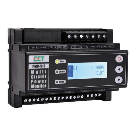
- Page 1 PMC-512-A AC Multi-Circuit Power Monitor User Manual Version: V1.1 July 4, 2018...
- Page 2 The information contained in this manual is believed to be accurate at the time of publication; however, CET assumes no responsibility for any errors which may appear here and reserves the right to make changes without notice. Please consult CET or your local representative for the latest product specifications.
- Page 3 CET Electric Technology DANGER Failure to observe the following instructions may result in severe injury or death and/or equipment damage. Installation, operation and maintenance of the meter should only be performed by qualified, competent personnel that have the appropriate training and experience with high voltage and current devices.
- Page 4 Limited warranty CET offers the customer a minimum of 12-month functional warranty on the meter for faulty parts or workmanship from the date of dispatch from the distributor. This warranty is on a return to factory for repair basis.
-
Page 5: Table Of Contents
Glossary ..............................7 Chapter 1 Introduction ..........................8 1.1 Overview ............................ 8 1.2 Features ............................8 1.3 PMC-512-A’ application in Monitoring Management Systems ..........10 1.4 Getting more information ......................10 Chapter 2 Installation ..........................11 2.1 Appearance ..........................11 2.2 Unit Dimensions ........................ - Page 6 CET Electric Technology 4.1 Inputs and Outputs ........................33 4.1.1 Digital Inputs ......................... 33 4.1.2 Analog Input ........................33 4.1.3 Energy Pulse Outputs ....................33 4.2 Power, Energy and Demand ..................... 34 4.2.1 Basic Measurements ..................... 34 4.2.2 Energy Measurements ....................34 4.2.3 Interval Energy Measurements ..................
- Page 7 CET Electric Technology 5.3.3 kWh and kvarh Energy Measurements for SMs and VMs ..........56 5.3.4 Interval Energy Measurements ..................56 5.4 DI Pulse Counter ........................57 5.5 Demands ..........................57 5.5.1 Present Demands ......................57 5.5.2 Peak Demand Log of This Month (Since Last Reset) ............. 58 5.5.3 Peak Demand Log of Last Month (Before Last Reset) ...........
-
Page 8: Glossary
CET Electric Technology Glossary = Cet Electric Technology 1-Ø = Single Phase 3-Ø = Three Phase = Sub Meter = Virtual Meter = Liquid Crystal Display = Present Demand = Power Quality Fund. = Fundamental = Total Harmonic Distortion TOHD... -
Page 9: Chapter 1 Introduction
Utility Substation Multi-Circuit Monitoring Power Quality Monitoring Maximum Demand Indicator The above are just a few of the many applications. Contact CET Technical Support should you require further assistance with your application. 1.2 Features Ease of use ... - Page 10 CET Electric Technology o Operating Time (Run Hour) 4x3-Ø SM o I per phase, I average and In (Calculated) o I Unbalance o Frequency o kW/kvar/kVA Total and PF total o kWh/kvarh Import/Export/Total and kVAh Total o kW/kvar/kVA Total Demand and Max. Demand with Timestamp...
-
Page 11: Pmc-512-A' Application In Monitoring Management Systems
Baud rate @ 1,200 to 57,600 System Integration The PMC-512-A is supported by CET’s PecStar iEMS. In addition, it can be easily integrated into other 3rd party Automation, Energy Management or SCADA systems because of its support of multiple communications ports and Modbus RTU protocol. -
Page 12: Chapter 2 Installation
Chapter 2 Installation Caution Installation of the PMC-512-A should only be performed by qualified, competent personnel that have the appropriate training and experience with high voltage and current devices. The meter must be installed in accordance with all local and national electrical codes. -
Page 13: Unit Dimensions
CET Electric Technology 2.2 Unit Dimensions 2.2.1 Main Unit Figure 2-3 Main Unit Dimension 2.2.1 HMI Front View Side View Figure 2-4 HMI Dimensions... -
Page 14: Overall Setup
Figure 2-6 Overall Installation 2.4 Mounting The PMC-512-A should be installed in a dry environment without dust and kept away from heat, radiation and electrical noise sources. The PMC-512-A is usually installed inside the PDU cabinet. Please reserve enough room for other accessories and make it convenient for future maintenance. -
Page 15: Branch Cts And Other Accessories
Move the installation clips at the back of the PMC-512-A downward to the “unlock” position. Align the top of the mounting channel at the back of the PMC-512-A at an angle against the top of the DIN rail as shown in figure below. - Page 16 CET Electric Technology 2.4.2.2 PMC-CT-250A-40mA-A (Solid-Core 1-Phase 250A CT) Figure 2-9 PMC-CT-250A-40mA-A Dimensions 2.4.2.3 PMC-CT-400A-40mA-A (Solid-Core 1-Phase 400A CT) Figure 2-10 PMC-CT-400A-40mA-A Dimensions 2.4.2.4 PMC-CT-800A-40mA-A (Solid-Core 1-Phase 800A CT) Figure 2-11 PMC-CT-800A-40mA-A Dimensions...
- Page 17 CET Electric Technology 2.4.2.5 PMC-SCCT-5A-1.667mA-10-A (Split-Core 1-Phase 5A CT) Figure 2-12 PMC-SCCT-5A-1.667mA-10-A Dimensions 2.4.2.6 PMC-SCCT-100A-40mA-16-A (Split-Core 1-Phase 100A CT) Figure 2-13 PMC-SCCT-100A-40mA-16-A Dimensions 2.4.2.7 PMC-SCCT-200A-40mA-24-A (Split-Core 1-Phase 200A CT) Figure 2-14 PMC-SCCT-200A-40mA-24-A Dimensions...
-
Page 18: Mounting The Hmi
CET Electric Technology 2.4.2.8 PMC-SCCT-400A-40mA-35-A (Split-Core 1-Phase 400A CT) Figure 2-15 PMC-SCCT-400A-40mA-35-A Dimensions 2.4.2.9 PMC-SCCT-800A-40mA-A (Split-Core 1-Phase 800A CT) Front View Side View Figure 2-16 PMC-SCCT-800A-40mA-A Dimensions 2.4.2.10 PMC-BCC-3CT (3-Phase Termination Connector) P1 Side PMC-512-A 1# S1 (+) I1 or I4 or I7 or I10... -
Page 19: Wiring Connections
Figure 2-17 Mounting the HMI 2.5 Wiring Connections The PMC-512-A provides 12 Current Inputs which can be configured as 12x1-Ø SM, 4x3-Ø SM or a combination of 1-Ø SMs or 3-Ø SMs. Regardless of the Wiring Mode, the PMC-512-A always relies on the relationship illustrated in Table 2-2 between Voltage Inputs (V1, V2, V3) and Current Inputs (I1 –... - Page 20 CET Electric Technology 4-Wire Wye (3P4W) Wiring with or without VG, 4-Wire Wye (3P4W) Wiring with VG and PTs 2.5.1.1 Single Phase (1P2W) Wiring Figure 2-18 1P2W with VG Figure 2-19 1P2W without VG 2.5.1.2 3-Wire Delta (3P3W) Wiring...
-
Page 21: Typical Application Wiring
1. The Molded-Case 3-Ø 100A CT comes standard with a 2m cable with a RJ12 connector. 2. Connect the RJ12 connector to the appropriate Current Inputs of the PMC-512-A. 3. Put the 3-phase primary conductors through the hole of the Solid-Core CT. - Page 22 Termination Adapter using a 0.5 to 1.0 mm wire (not included). 3. Connect the RJ12 connector to the appropriate Current Inputs of the PMC-512-A. 4. Re-install the CT’s output terminal cover. 5. Put the primary conductor through the hole of the Solid-Core CT.
-
Page 23: Communications Wiring
CET Electric Technology 2.5.4 Communications Wiring The PMC-512-A provides two standard RS485 ports and supports the Modbus RTU protocol. Up to 32 devices can be connected on each RS485 bus. The overall length of the RS485 cable connecting all devices should not exceed 1200m. -
Page 24: Digital Output Wiring
CET Electric Technology 2.5.7 Digital Output Wiring The following figure illustrates the Digital Output connections on the PMC-512-A: Figure 2-32 DO Wiring 2.5.8 PMC-512-A Power Supply Wiring For AC supply, connect the live wire to the L/+ terminal and the neutral wire to the N/- terminal. -
Page 25: Chapter 3 Front Panel
CET Electric Technology Chapter 3 Front Panel The PMC-512-A has an easy to read LCD display and three buttons for both data display and setup configuration purposes. Figure 3-1 Front Panel 3.1 Front Panel LED Indicators There are three LED indicators on the PMC-512-A’s front panel as described in the following table. -
Page 26: Data Display
Table 3-2 Buttons Description 3.3 Data Display The PMC-512-A’s LCD defaults to an Auto-Scroll display mode where measurements in each of the selected Parameter Categories illustrated in Table 3-3 below are automatically scrolled through at a fixed 5-second interval. If the user wishes to see all the available parameters, one can manually do so by entering the Main Menu by pressing the <... -
Page 27: Metering
Table 3-6 DI/DO Status Display Pages 3.3.5 SOE Log The PMC-512-A supports the display of the SOE Log with its relevant parameter values and its >. timestamp. The users can scroll through the SOE Log by pressing < > or <... -
Page 28: Information
CET Electric Technology Figure 3-2 Examples of Event Log Display 3.3.6 Information Menu Description Parameters Info Meter Information Firmware Firmware Version Modbus Modbus Protocol Version Ver. Date Firmware Version Date Serial Number Diagnostics A/D Diagnostics FRAM FRAM Diagnostics FLASH FLASH Diagnostics Setup Param. -
Page 29: Setup Menu
CET Electric Technology Also, the Setup Configuration Mode will be automatically exited if there is a period of inactivity of 5 minutes or longer. 3.4.2 Setup Menu Figure 3-3 Setup Menu... -
Page 30: Configuration
CET Electric Technology 3.4.3 Configuration The Setup Configuration Mode provides access to the following setup parameters: Label Menu Description Range Default Setup Basic Nom. Freq. Nominal Frequency 50Hz/60Hz 50Hz 3P4W/3P3W/ Wiring Mode Meter’s Wiring Connection 3PH4W 1P2W/DEMO U Primary PT Primary... - Page 31 CET Electric Technology None Enable Ull Alarm Enable U12/U23/U31 HH Limit Ull HH Alarm Threshold 0~500.0 (V) HH Delay Ull HH Alarm Delay 0~9999 (s) H Limit Ull H Alarm Threshold 0~500.0 (V) H Delay Ull H Alarm Delay 0~9999 (s)
-
Page 32: Maintenance
CET Electric Technology CT Type CT Type Solid/Split Solid VM Setup (1-6) Select SM1-SM6 to be included 1 2 3 4 5 6 Enable 1-6 □□□□□□ in a VM’s aggregation Select SM7-SM12 to be included 7 8 9 10 11 12 Enable 7-12 □□□□□□... - Page 33 Auto-Scroll Setup allows users to select which 1-Ø SM, 3-Ø SM or VM would be displayed in Auto-Scroll Mode. For example, if the PMC-512-A is used to monitor three 3-Ø circuits with I1 to I9, three 1-Ø circuits with I10 to I12 and without any virtual metering, the 1-Ø...
-
Page 34: Chapter 4 Applications
4.1 Inputs and Outputs 4.1.1 Digital Inputs The PMC-512-A is equipped with 12 wet contact Digital Inputs (DIs) that can be used for the status monitoring which can help if a circuit is energized, detect breaker status or prevent misoperation to equipment. -
Page 35: Power, Energy And Demand
CT is 100A, then it is recommended to set the Energy Pulse Constant to 400 imp/kxh. 4.2 Power, Energy and Demand 4.2.1 Basic Measurements The PMC-512-A provides the following basic measurements which can be accessed via the Front Panel or through the communication: Parameter 1-Ø... -
Page 36: Demands
Table 4-5 Demand Setup 4.3 Alarm Setpoints The PMC-512-A provides powerful alarming functions for the 1-Ø SMs, 3-Ø SMs as well as for different parameters. Each Alarm Type can be independently enabled, and a particular alarm within each Alarm Type may also be disabled individually by setting its Alarm Threshold to 0. -
Page 37: Universal Hysteresis And Current On/Off Status
Return Threshold = Alarm Threshold x (1 + Universal Hysteresis) The PMC-512-A provides the ON/OFF status for each Current channel to indicate whether the channel is ON (Loaded) or OFF (No Load). If the Channel status is OFF, it means that the channel has no load and would prevent the Low and Low-Low alarms from activating. -
Page 38: Current Alarms
Figure 4-4 Current ON/OFF Status 4.3.3 Current Alarms PMC-512-A provides the Current On/OFF status as well as four Current Alarm Levels (High-High, High, Low and Low-Low) for the 12x1-Ø SM. The Current Alarms will only be evaluated if it’s determined that the Current ON status is true. -
Page 39: Voltage Alarm
CET Electric Technology The logic diagram of the Current HH Alarm is illustrated in Figure 4-5. Figure 4-5 Current HH Alarm Logic Diagram The logic diagram of the Current H Alarm is illustrated in Figure 4-6. Figure 4-6 Current H Alarm Logic Diagram The logic diagram of Current L Alarm is illustrated in Figure 4-7. -
Page 40: Frequency Alarm
Figure 4-9 Voltage HH/H Alarm Logic Diagram The logic diagram of Voltage L/LL Alarm is illustrated in Figure 4-10. Figure 4-10 Voltage L/LL Alarm Logic Diagram 4.3.5 Frequency Alarm PMC-512-A provides two Frequency Alarm levels (High, Low). Since PMC-512-A measures its frequency... -
Page 41: Unbalance Alarm
The logic diagram of FREQ L Alarm is illustrated in Figure 4-12. Figure 4-12 FREQ L Alarm Logic Diagram 4.3.6 Unbalance Alarm The PMC-512-A provides Current Unbalance Alarm for 4x3-Ø SMs. The following table illustrates the Unbalance Alarm parameters. Parameters... -
Page 42: Phase Reversal Alarm
The logic diagram of Unbalance Alarm is illustrated in Figure 4-13. Figure 4-13 Unbalance Alarm Logic Diagram 4.3.7 Phase Reversal Alarm The PMC-512-A supports Phase Reversal Setpoint Alarms for 4x3-Ø SM. The following table illustrates the Phase Reversal Alarm parameters and their respective default values. Parameters... -
Page 43: Ai Alarm
The logic diagram of Phase Loss Alarm is illustrated in Figure 4-15. Figure 4-15 Phase Loss Alarm Logic Diagram 4.3.9 AI Alarm PMC-512-A provides four AI Alarm Levels (High-High, High, Low, Low-Low). The following table illustrates the AI Alarm parameters. Parameters... -
Page 44: Di Alarm
4.4 Power Quality 4.4.1 Phase Angles The PMC-512-A provides Voltage and Current Phase Angle measurements for 1-Ø SMs and 3-Ø SMs. Phase analysis is used to identify the angle relationship between voltages and currents. For WYE connected systems, the per phase difference of the current and voltage angles should correspond to the per phase PF. -
Page 45: Harmonics
Table 4-15 Harmonics Measurements 4.5 Sub-Meters (SM) The PMC-512-A provides 12 Current Inputs which can be configured as 12x1-Ø SM, 4x3-Ø SM or a combination of 1-Ø SMs or 3-Ø SMs. The SM assignment principle is illustrated in Tables 4-16. -
Page 46: Virtual Meters (Vm)
4.6 Virtual Meters (VM) The PMC-512-A supports up to four Virtual Meters, VM1 to VM4, which can be used to perform arbitrary aggregation from any of the 12 individual 1-Ø SMs, please refer to Section 5.8.7 VM Setup for more information. -
Page 47: Soe Log
4.7.3 Daily Freeze Log The PMC-512-A provides a Daily Freeze Log of Current, Power and Energy parameters for 1-Ø SMs, 3-Ø SMs and VMs for the last 1000 days. The Daily Freeze Log is stored in the meter’s non-volatile memory and will not suffer any loss in the event of power failure, and they are stored on a First-In-First-Out (FIFO) basis where the newest log will overwrite the oldest. - Page 48 CET Electric Technology The programming of the DR is only supported over communications. The DR provides the following setup parameters: Setup Parameters Value/Option Default Trigger Mode 0=Disabled / 1=Enabled Recording Mode 0=Stop-When-Full / 1=First-In-First-Out Recording Depth 1 to 5000 (entry)
-
Page 49: Chapter 5 Modbus Register Map
This chapter provides a complete description of the Modbus register map (Protocol Versions 2.1) for the PMC-512-A to facilitate the development of 3 party communications driver for accessing information on the PMC-512-A. For a complete Modbus Protocol Specification, please visit www.modbus.org. The PMC-512-A supports the following Modbus functions:... -
Page 50: Instantaneous Alarms
CET Electric Technology where Log Depth = 512 for SOE Log, 1000 for Daily Freeze Log, 24 for Monthly Freeze Log and DR’s Recording Depth for the DR Log. 5.1.2 Instantaneous Alarms Register Property Description Format Note 0030 Instantaneous Alarm Status #1... -
Page 51: Latched Alarms
CET Electric Technology Bit 15 Bit 14 Bit 13 Bit 12 Status Reserved Ung HH Ung H Phase Loss Table 5-8 Instantaneous Alarm Status #5 (Register 0034) Bit 3 Bit 2 Bit 1 Bit 0 3-Ø SM2 3-Ø SM2 3-Ø SM1 3-Ø... -
Page 52: Basic Measurements
CET Electric Technology Status 1-Ø SM10 I LL 1-Ø SM10 I HH 1-Ø SM10 I L 1-Ø SM10 I H Bit 11 Bit 10 Bit 9 Bit 8 Status 1-Ø SM11 I LL 1-Ø SM11 I HH 1-Ø SM11 I L 1-Ø... - Page 53 CET Electric Technology 0522 U1 Angle FP32 0524 U2 Angle FP32 0526 U3 Angle FP32 ° 0528 U12 Angle FP32 0530 U23 Angle FP32 0532 U31 Angle FP32 0534 1-Ø SM1 Current FP32 0536 1-Ø SM2 Current FP32 … …...
-
Page 54: Measurements For Hmi
CET Electric Technology 0766 VM1 kVA FP32 0768 VM2 kVA FP32 0770 VM3 kVA FP32 0772 VM4 kVA FP32 0774 AI (Raw) UINT16 x0.01 0775 AI (Scaled) FP32 Table 5-19 Real-time Measurements 5.2.2 Measurements for HMI Register Property Description Format... -
Page 55: Operating Time
CET Electric Technology 5.2.3 Operating Time Register Property Description Format Scale Unit 1500 1-Ø SM1 Operating Time UINT32 1502 1-Ø SM2 Operating Time UINT32 … UINT32 1522 1-Ø SM12 Operating Time UINT32 x0.1 Hour 1524 3-Ø SM1 Operating Time UINT32 1526 3-Ø... -
Page 56: Complete Energy Measurements Based On Sms And Vms
CET Electric Technology 2176 VM1 kWh Import INT32 2178 VM2 kWh Import INT32 2180 VM3 kWh Import INT32 2182 VM4 kWh Import INT32 x0.01 2184 VM1 kWh Export INT32 2186 VM2 kWh Export INT32 2188 VM3 kWh Export INT32 2190... -
Page 57: Kwh And Kvarh Energy Measurements For Sms And Vms
CET Electric Technology 2506 VM4 kWh Import INT32 x0.01 2508 VM4 kWh Export INT32 2510 VM4 kvarh Import INT32 x0.01 kvarh 2512 VM4 kvarh Export INT32 2514 VM4 kVAh INT32 x0.01 kVAh Table 5-23 Complete Energy Measurement based on SMs and VMs 5.3.3 kWh and kvarh Energy Measurements for SMs and VMs... -
Page 58: Di Pulse Counter
CET Electric Technology 3292 VM2 kvarh Export INT32 3294 VM2 kVAh INT32 x0.01 kVAh 3296 VM3 kWh Import INT32 x0.01 3298 VM3 kWh Export INT32 3300 VM3 kvarh Import INT32 x0.01 kvarh 3302 VM3 kvarh Export INT32 3304 VM3 kVAh INT32 x0.01... -
Page 59: Peak Demand Log Of This Month (Since Last Reset)
CET Electric Technology 3614 3-Ø SM2 kVA FP32 3616 3-Ø SM3 kVA FP32 3618 3-Ø SM4 kVA FP32 3620 VM1 kW FP32 3622 VM2 kW FP32 3624 VM3 kW FP32 3626 VM4 kW FP32 3628 VM1 kvar FP32 3630 VM2 kvar... -
Page 60: Peak Demand Log Of Last Month (Before Last Reset)
CET Electric Technology 4228 3-Ø SM2 kVA FP32 4230 Timestamp UINT32 4232 3-Ø SM3 kVA FP32 4234 Timestamp UINT32 4236 3-Ø SM4 kVA FP32 4238 Timestamp UINT32 4240 VM1 kW FP32 4242 Timestamp UINT32 4244 VM2 kW FP32 4246 Timestamp... -
Page 61: Harmonics Measurements
CET Electric Technology 4486 Timestamp UINT32 4488 3-Ø SM3 kW FP32 4490 Timestamp UINT32 4492 3-Ø SM4 kW FP32 4494 Timestamp UINT32 4496 3-Ø SM1 kvar FP32 4498 Timestamp UINT32 4500 3-Ø SM2 kvar FP32 4502 Timestamp UINT32 4504 3-Ø SM3 kvar... -
Page 62: Current Thd Measurements
CET Electric Technology 5.6.2 Current THD Measurements Register Property Description Format Scale Unit 4718 1-Ø SM1 THD FP32 4720 1-Ø SM1 TOHD FP32 4722 1-Ø SM1 TEHD FP32 4724 1-Ø SM2 THD FP32 4726 1-Ø SM2 TOHD FP32 4728 1-Ø SM2 TEHD... -
Page 63: Log Register
CET Electric Technology HD03 FP32 x100, % HD04 FP32 x100, % HD05 FP32 x100, % … … … FP32 … HD29 FP32 x100, % HD30 FP32 x100, % HD31 FP32 x100, % Table 5-33 HD Data Structure 5.7 Log Register 5.7.1 SOE Log... - Page 64 CET Electric Technology 20214 1-Ø SM12 kWh Export INT32 x0.01 20216 1-Ø SM12 kvarh Import INT32 x0.01 kvarh 20218 1-Ø SM12 kvarh Export INT32 x0.01 kvarh 20220 1-Ø SM12 kVAh INT32 x0.01 kVAh 20222 3-Ø SM1 kW FP32 20224 3-Ø SM1 kvar...
-
Page 65: Monthly Freeze Log
CET Electric Technology 5.7.3 Monthly Freeze Log Register Property Description Format Scale Unit 2700 Index UINT16 0 to 24 High-order Byte: Year (0-99) 2701 UINT16 Low-order Byte: Month (1-12) Time Stamp High-order Byte: Day (1-31) 2702 UINT16 (20YY/MM/DD Low-order Byte: Hour (0-23) -
Page 66: Data Recorder Log
CET Electric Technology 5.7.4 Data Recorder Log Register Property Description Format 21000 DR Log x Index UINT32 High-order Byte: Year (0-99) 21002 UINT16 Low-order Byte: Month (1-12) High-order Byte: Day (1-31) 21003 UINT16 Low-order Byte: Hour (0-23) High-order Byte: Minute (0-59) -
Page 67: Ai Setup
CET Electric Technology Notes: The value of [PT Primary/PT Secondary] cannot exceed 10000. The Self-Read Time applies to both the Peak Demand Log as well as the Monthly Freeze Log and supports the following two options: A zero value means that the Self-Read will take place at 00:00 of the first day of each month. -
Page 68: Alarm Setup
CET Electric Technology 5.8.5 Alarm Setup Register Property Description Format Range, Default* 6400 Universal Hysteresis UINT16 0 to 100 (x0.1%), 20* 6401 Current ON Threshold UINT16 0 to 100 (x0.1%), 50* 6402 Current ON Time Delay UINT16 0 to 9999 (s), 10s*... - Page 69 CET Electric Technology 2 = DI1 Open Trigger 6458 DI1 Alarm Time Delay UINT16 0* to 9999 (s) 6459 DI1 Alarm Trigger Bitmap 0*~0x0003 … … 0 = Disabled* 6490 DI12 Alarm Configuration UINT16 1 = DI12 Closed Trigger 2 = DI12 Open Trigger...
-
Page 70: 1-Ø Sms Setup Parameters
CET Electric Technology Reserved 3-Ø SM4 Table 5-49 I Unbalance Alarm Enabled Register The following table illustrates the details of the Phase Reversal Alarm Enable register with a bit value of 1 meaning enabled and 0 meaning disabled. Bit 2... -
Page 71: Vm Setup
5.9 Time Registers There are two sets of Time registers supported by the PMC-PMC-512-A – Year / Month / Day / Hour / Minute / Second (Registers # 60000 to 60002) and UNIX Time (Register # 60004). When sending time to the PMC-512-A over Modbus communications, care should be taken to only write one of the two Time register sets. -
Page 72: Clear/Reset Control
The DO Control registers are implemented as both “Write-Only” Modbus Coil Registers (0XXXXX) and Modbus Holding Registers (4XXXXX), which can be controlled with the Force Single Coil command (Function Code 0x05) or the Preset Multiple Hold Registers (Function Code 0x10). The PMC-512-A does... -
Page 73: Meter Information
Read Coils command (Function Code 0x01) because DO Control registers are “Write- Only”. The PMC-512-A adopts the ARM before EXECUTE operation for the remote control of its Digital Outputs if this function is enabled through the Arm Before Execute Enable Setup register (6014), which is disabled by default. - Page 74 CET Electric Technology 60205 9805 0x31 60206 9806 0x32 60207 9807 0x2D 60208 9808 0x41 60209-60219 9809-9819 0x20 <Null> Table 5-62 ASCII Encoding of “PMC-512-A”...
-
Page 75: Appendix A - Soe Event Classification
CET Electric Technology Appendix A - SOE Event Classification Event Sub- Channel Event Value Description Classification Classification DI1 Close/DI1 Open DI2 Close/DI2 Open DI3 Close/DI3 Open DI4 Close/DI4 Open DI5 Close/DI5 Open DI6 Close/DI6 Open DI7 Close/DI7 Open DI8 Close/DI8 Open... - Page 76 CET Electric Technology Configuration First Power On A/D Fault Internal Power Fault FRAM Fault FLASH Fault System Parameters Fault Internal Parameters Fault Notes: 1) The following table provides a detailed description of the Channel Number. Channel Number Description Channel Number Description 3-Ø...
-
Page 77: Appendix B - Data Recorder Parameters
CET Electric Technology Appendix B - Data Recorder Parameters 1-Ø SMs Real-time and Demand Measurements Description Description 1~10 1-Ø SM 1 61~70 1-Ø SM 7 11~20 1-Ø SM 2 71~80 1-Ø SM 8 21~30 1-Ø SM 3 81~90 1-Ø SM 9 31~40 1-Ø... - Page 78 CET Electric Technology VM Group Structure Offset Description kW Total kvar Total kVA Total kW Total Demand kvar Total Demand kVA Total Demand Harmonic Measurements U Harmonic Measurements Description Description U1 THD U2 TEHD U1 TOHD 370~383 U2 HD2~ HD15...
- Page 79 CET Electric Technology 3-Ø SM Energy Measurements Description Description 714~719 3-Ø SM1 726~731 3-Ø SM3 720~725 3-Ø SM2 732~737 3-Ø SM4 3-Ø SM Energy Group Structure Offset Description kvarh Total kWh Import Total kWh Export Total kvarh Import Total kvarh Export Total...
-
Page 80: Appendix C - Data Recorder Default Settings
CET Electric Technology Appendix C - Data Recorder Default Settings Register Property Description Format Range/Options Default 0=Disabled, 6900 Trigger Mode UINT16 1=Enabled 0=Stop-When-Full 6901 Recording Mode UINT16 1=First In First Out 1=First In First Out 6902 Recording Depth UINT16 0 to 5000... - Page 81 CET Electric Technology 6961 Parameter 55 UINT16 1-Ø SM 12 Current Demand 6962 Parameter 56 UINT16 None 6963 Parameter 57 UINT16 None 6964 Parameter 58 UINT16 None 6965 Parameter 59 UINT16 None 6966 Parameter 60 UINT16 None...
-
Page 82: Appendix D - Mains Circuit Ct
CET Electric Technology Appendix D - Mains Circuit CT Ordering Guide Specification PMC-CT-100A-40mA-3P-A Operating Temperature -40°C~+85°C Storage Temperature -40°C to +85°C Environment Humidity ≤95% Atmospheric Pressure 80-110kpa Primary Current (In) Magnitude Nonlinearity ≤0.1% Secondary Current Phase Nonlinearity ≤10' Linearity Range... - Page 83 CET Electric Technology PMC-CT-250A-40mA-A Operating Temperature -40°C~+85°C Storage Temperature -40°C to +85°C Environment Humidity ≤95% Atmospheric Pressure 80-110kpa Primary Current (In) 250A Magnitude Nonlinearity ≤0.2% Secondary Current 40mA Phase Nonlinearity ≤15' Linearity Range 5%In-120xIn Internal DC Resistance 365±40Ω (20°C)
- Page 84 CET Electric Technology PMC-SCCT-5A-1.667mA-10-A Operating Temperature -20°C~+50°C Storage Temperature -40°C to +85°C Environment Humidity ≤85% Atmospheric Pressure 70-106kpa Primary Current (In) Magnitude Error ±0.8% Secondary Current 1.667mA Phase Error 90±15' Max. Current (Imax) 10A, continuous Rated Load 200Ω Technical...
- Page 85 CET Electric Technology PMC-SCCT-400A-40mA-35-A Operating Temperature -20°C~+50°C Storage Temperature -40°C to +85°C Environment Humidity ≤85% Atmospheric Pressure 70-106kpa Primary Current (In) 400A Magnitude Error ±0.5% Secondary Current 40mA Phase Angle 10±10' Max. Current (Imax) 480A, continuous Rated Load 10Ω...
-
Page 86: Appendix E - Technical Specifications
CET Electric Technology Appendix E - Technical Specifications Voltage Inputs (V1, V2, V3, VN) 240VLN/415VLL Range 10V to 1.2Un Start Voltage Overload 1.2xUn continuous, 2xUn for 10s Burden <0.05VA per phase Range 0~5V Frequency 45-65Hz Current Inputs (I11, I12, I21, I22, I31, I32) -
Page 87: Appendix F - Accuracy Specifications
CET Electric Technology Appendix F - Accuracy Specifications Parameters Accuracy Resolution Voltage ±0.5% 0.01V Current ±0.5% 0.001A Phase Angle ±1° 0.1° kW, kvar, kVA ±1.0% 0.001kX IEC 62053-21: 2003 Class 1 0.01kWh kvarh IEC 62053-22: 2003 Class 2 0.001kvar ±1.0% P.F. -
Page 88: Appendix G - Standards Compliance
CET Electric Technology Appendix G - Standards Compliance Safety Requirements CE LVD 2014 / 35 / EU EN 61010-1: 2010, EN 61010-2-030: 2010 Electrical safety in low voltage distribution systems up to 1000Vac IEC 61557-12: 2008 and 1500 Vdc Dielectric test: Insulation... -
Page 89: Appendix H - Ordering Guide
CET Electric Technology Appendix H - Ordering Guide... -
Page 90: Contact Us
Contact us CET Inc. 8/F, Westside, Building 201, Terra Industrial & Trade park, Che Gong Miao, Shenzhen, Guangdong, P.R.China 518040 Tel: +86.755.8341.5187 Fax: +86.755.8341.0291 Email: sales@cet-global.com Web: www.cet-global.com...
Need help?
Do you have a question about the PMC-512-A and is the answer not in the manual?
Questions and answers