
Subscribe to Our Youtube Channel
Related Manuals for CET PMC-53 Series


Summary of Contents for CET PMC-53 Series
- Page 1 PMC-53 Series Intelligent Multifunction Meter User Manual Version: V5.2A 02/07/2012 Ceiec Electric Technology...
- Page 2 The information contained in this manual is believed to be accurate at the time of publication; however, CET assumes no responsibility for any errors which may appear here and reserves the right to make changes without notice. Please consult CET or your local representative for the latest product specifications.
- Page 3 Ceiec Electric Technology DANGER Failure to observe the following instructions may result in severe injury or death and/or equipment damage. Installation, operation and maintenance of the meter should only be performed by qualified, competent personnel that have the appropriate training and experience with high voltage and current devices.
- Page 4 CET does not accept liability for any damage caused by meter malfunctions. CET accepts no responsibility for the suitability of the meter to the application for which it was purchased. Failure to install, set up or operate the meter according to the instructions herein will void the warranty.
-
Page 5: Table Of Contents
Chapter 1 Introduction ..........................7 1.1 Overview ............................ 7 1.2 Features ............................7 1.3 PMC-53 series’ application in Power and Energy Management Systems ........9 1.4 Getting more information ......................10 Chapter 2 Installation ..........................11 2.1 Appearance ..........................11 2.2 Unit Dimensions ........................ - Page 6 Ceiec Electric Technology 4.1.5 Temperature Input ......................32 4.2 Power and Energy ........................32 4.2.1 Voltage and Current Phase Angles ................32 4.2.2 Energy ........................... 32 4.2.3 Demands ........................33 4.3 Setpoints ..........................33 4.3.1 Control Setpoints ......................33 4.3.2 Digital Input Setpoints....................34 4.3.3 I residual Setpoints ......................
-
Page 7: Chapter 1 Introduction
This manual explains how to use the PMC-53 Series Intelligent Multifunction Meter. Throughout the manual the term “meter” generally refers to all models. Differences between the models are indicated with the appropriate model number. This chapter provides an overview of the PMC-53 series meter and summarizes many of its key features. 1.1 Overview The PMC-53 Series Intelligent Multifunction Meter is CET’s latest offer for the low-cost digital... - Page 8 Ceiec Electric Technology Ease of use Large, backlit, easy to read, 5-line LCD display with wide viewing angle Password-protected setup via front panel or free PMC Setup software Easy installation with mounting clips, no tools required Built in alarm buzzer for optional I residual and Temperature alarms Setpoints ...
-
Page 9: Pmc-53 Series' Application In Power And Energy Management Systems
RTD Temperature Input DO or SS Relay * Available in Firmware Version V1.20.01 or later 1.3 PMC-53 series’ application in Power and Energy Management Systems The PMC-53 can be used to monitor Wye or Delta connected power system. Modbus communications allow real-time data, events, DI status and other information to be transmitted across... -
Page 10: Getting More Information
Ceiec Electric Technology 1.4 Getting more information Additional information is available from CET via the following sources: Visit www.ceiec-electric.com Contact your local representative Contact CET directly via email or telephone... -
Page 11: Chapter 2 Installation
Ceiec Electric Technology Chapter 2 Installation Caution Installation of the PMC-53 should only be performed by qualified, competent personnel that have the appropriate training and experience with high voltage and current devices. The meter must be installed in accordance with all local and national electrical codes. During the operation of the meter, hazardous voltages are present at the input terminals. -
Page 12: Unit Dimensions
Ceiec Electric Technology 2.2 Unit Dimensions Figure 2-2 Dimensions 2.3 Mounting The PMC-53 series meter should be installed in a dry environment with no dust and kept away from heat, radiation and electrical noise source. Installation steps: Remove the installation clips from the meter ... -
Page 13: Wiring Connections
Ceiec Electric Technology 2.4 Wiring connections PMC-53 can satisfy almost any three phase power systems. Please read this section carefully before installation and choose the correct wiring method for your power system. The following Wiring Modes are supported: 3-phase 4-wire Wye Direct Connection ... -
Page 14: 3-Phase 4-Wire Wye With 3Pts And 3Cts
Ceiec Electric Technology 2.4.2 3-phase 4-wire Wye with 3PTs and 3CTs Please consult the serial number label to ensure that the rated PT secondary voltage is less than or equal to the meter’s voltage input specification. Set the Wiring Mode to Wye. Figure 2-5 4-Wire Wye, 3PTs, 3CTs 2.4.3 3-phase 3-wire Open Delta Direct Connection Please consult the serial number label to ensure that the rated PT secondary voltage is less than or... -
Page 15: 3-Phase 3-Wire Open Delta With 2Pts And 3Cts
Ceiec Electric Technology 2.4.4 3-phase 3-wire Open Delta with 2PTs and 3CTs Please consult the serial number label to ensure that the rated PT secondary voltage is less than or equal to the meter’s voltage input specification. Set the Wiring Mode to Delta. Figure 2-7 3-Wire DELTA, 2PTs, 3CTs 2.4.5 3-phase 3-wire Open Delta with 2PTs and 2CTs Please consult the serial number label to ensure that the rated PT secondary voltage is less than or... -
Page 16: Communications Wiring
Ceiec Electric Technology 2.5 Communications Wiring The following figure illustrates the RS485 communications connections on the PMC-53: Figure 2-9 Communications Connections The PMC-53 provides one RS485 port and supports the Modbus RTU protocol. Up to 32 devices can be connected on a RS485 bus. The overall length of the RS485 cable connecting all devices should not exceed 1200m. -
Page 17: Pulse Output Wiring
Ceiec Electric Technology 2.8 Pulse Output Wiring The following figure illustrates the Pulse Output connections on the PMC-53: Figure 2-12 Pulse Output Connections 2.9 I residual Input Wiring The following figure illustrates the I residual connections on the PMC-53: Figure 2-13 I residual Connections 2.10 Temperature Input Wiring The following figure illustrates the Temperature Input connections on the PMC-53: Figure 2-14 Temperature Input Connections... -
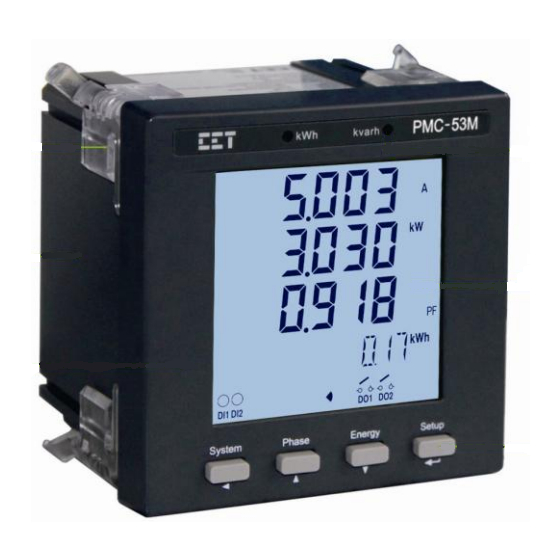
Page 18: Chapter 3 Front Panel
Ceiec Electric Technology Chapter 3 Front Panel The PMC-53 series meter has a large, easy to read LCD display with backlight and four buttons for data display and meter configuration. This chapter introduces the front panel operations. Figure 3-1 Front Panel 3.1 LCD Display... - Page 19 Ceiec Electric Technology C: Displays the indicators for DI status, DO status, Harmonic Distortion (HD), Unbalance (unb), PF Quadrant and Alarm status D: Displays Measurement values E: Displays Measurement Units Figure 3-3 LCD Display The following table shows the special LCD display symbols: Area Segments Symbol Description...
-
Page 20: Peak Demand Display
Ceiec Electric Technology 3.1.3 Peak Demand Display The following special arrangements have been made for the display of the Peak Demand value and its timestamp with the appropriate units displayed in the Measurement Units area. Peak Demand Indicator - Ia, Ib, Ic, kW Import, kvar Import, kVA Total Peak Demand value Date portion of the Peak Demand timestamp Time portion of the Peak Demand timestamp... -
Page 21: Default Screen
Ceiec Electric Technology 3.3.1 Default Screen There is a default display screen for the PMC-53M as illustrated in Figures 3-5. If there is no activity for 3 minutes, the display will automatically return to the default display screen. Figure 3-5 PMC-53M Default Display 3.3.2 Data Display The following tables illustrate the display screens for the different PMC-53 models. -
Page 22: Setup Configuration Via The Front Panel
Ceiec Electric Technology Display 3 Display 4 Display 5 kvara kvarb kvarc Display 6 kVAa kVAb kVAc Display 7 P.F.a P.F.b P.F.c Display 8* dP.F.a dP.F.b dP.F.c Display 9* Va THD Vb THD Vc THD Display 10* Ia THD Ib THD Ic THD Display 11* Ia K-Factor... -
Page 23: Reset The Alarm Led And Buzzer
Ceiec Electric Technology <Phase>: Before a parameter is selected for modification, pressing this button advances to the next parameter in the menu. If a parameter is already selected, pressing this button increments a numeric value or advances to the next value in the selection list. <Energy>: Before a parameter is selected for modification, pressing this button goes back to the last parameter in the menu. -
Page 24: Setup Menu
Ceiec Electric Technology 3.4.3 Setup Menu Figure 3-6 Setup Menu... -
Page 25: Configuration
Ceiec Electric Technology 3.4.4 Configuration The Setup Configuration mode provides access to the following setup parameters: Label PMC-53 Model Parameters Description Option(value) Default Menu Setup PROGRAMMING Configuration ■ ■ ■ Mode PASSWORD Password Enter Password “0” ■ ■ ■ Change SET PASS YES/NO ■... - Page 26 Ceiec Electric Technology Enable Temperature ALM TMP Temperature ON/OFF ■ ALARM ALARM Temperature TMP SP Temperature 55 -140(°C) ■ ALARM SP ALARM Setpoint Temperature TMP DLY Temperature 0 - 400(x0.1s) ■ ALARM Delay ALARM Delay Temperature Temperature TMP DO1 ON/OFF ■...
- Page 27 Ceiec Electric Technology 1k(1000)/3.2k(3200)/ EN CONST Pulse Constant Pulse Constant 5k(5000)/6.4k(6400)/ ■ 12.8k(12800) Clear kWh, CLR ENGY Clear Energy YES/NO ■ kvarh and kVAh Clear Peak CLR DMD* Clear Demand YES/NO ■ Demands CLR SOE Clear SOE Clear SOE Log YES/NO ■...
- Page 28 Ceiec Electric Technology Power Factor Convention Figure 3-7 P.F. Convention There are two ways to calculate kVA: kvar Mode V (Vector method): total total total Mode S (Scalar method): total This menu only appears if the PMC-53 is equipped with the I residual and Temperature Inputs.
- Page 29 Ceiec Electric Technology The PMC-53M provides the following pulse constant configurations for different input ratings: PMC-53M Configurations Pulse Constant Options (imp/kWh, imp/kvarh) Default 57.75VLN/100VLL, 1A 1000/3200/5000/6400/12800 1000 57.75VLN/100VLL, 5A 1000/3200/5000/6400/12800 1000 220VLN/380VLL, 1A 1000/3200/5000/6400/12800 1000 220VLN/380VLL, 5A 1000/3200/5000 1000 Table 3-7 Pulse Constant...
-
Page 30: Chapter 4 Applications
Ceiec Electric Technology Chapter 4 Applications 4.1 Inputs and Outputs 4.1.1 Digital Inputs The PMC-53 optionally provides two self-excited Digital Inputs that are internally wetted at 24 VDC. Digital Inputs are typically used for monitoring external status which can help prevent equipment damage, improve maintenance, and track security breaches. -
Page 31: Energy Pulse Outputs
Ceiec Electric Technology Control has the highest priority and can override any other applications. Next in the priority list is Remote Control. I residual Setpoints, Temperature Setpoint and Digital Input Setpoints share the same priority, meaning that they can all be programmed to control the same Digital Output. This scheme is equivalent to having an implicit Logical OR operation for the control of a Digital Output and may be useful in providing a generic alarm output signal. -
Page 32: Temperature Input
Ceiec Electric Technology Figure 4-1 I Residual Connections 4.1.5 Temperature Input The PMC-53 optionally provides a RTD Temperature Input along with an external RTD Temperature Sensor (see Appendix C) to provide temperature measurement. The outputs of the Temperature Sensor are connected to the Temperature Input of the PMC-53 if so equipped. The Temperature Input provides accurate temperature monitoring and is mainly used for measuring the temperature of the Neutral Conductor, Transformer or other equipment that requires temperature monitoring. -
Page 33: Demands
Ceiec Electric Technology Active Energy kWh Import kWh Export Reactive Energy kvarh Import kvarh Export Apparent Energy kVAh Total Table 4-1 Energy 4.2.3 Demands Demand is defined as the average power consumption over a fixed interval (usually 15 minutes). The PMC-53 supports the sliding window demand calculation for Ia, Ib, Ic, kW Total, kvar Total and kVA Total. -
Page 34: Digital Input Setpoints
Ceiec Electric Technology Setpoint Limit: Specifies the value that the setpoint parameter must exceed for Over Setpoint or go below for Under Setpoint for the setpoint to become active. The Setpoint Return Limit is 0.95xSetpoint Limit for Over Setpoint and 1.05xSetpoint Limit for Under Setpoint. Setpoint Delay: Specifies the minimum duration in seconds that the setpoint condition must be met before the setpoint becomes active. -
Page 35: I Residual Setpoints
Ceiec Electric Technology holding down the <System> open 1 second later. button for 3 seconds or via communications. Table 4-4 Digital Input Setpoint Details 4.3.3 I residual Setpoints The I residual Setpoints can be used to monitor residual current and provide alarming and control capability if the residual current exceeds a pre-determined level. -
Page 36: Temperature Setpoint
Ceiec Electric Technology enabled) must be reset manually by holding down the <System> button for 3 seconds or via communications after the I residual ALARM has become inactive. Table 4-5 I Residual ALARM and TRIP Setpoints 4.3.4 Temperature Setpoint The Temperature Setpoint can be used to monitor equipment temperature and provide alarming and control capability if the temperature measurement exceeds a pre-determined level. -
Page 37: Power Quality
Ceiec Electric Technology front panel or via communications. 4.5 Power Quality 4.5.1 Harmonics The PMC-53 provides harmonic analysis for THD. All harmonic parameters are available through communications as well as the front panel LCD display. The PMC-53 provides the following Harmonic measurements: Va THD Vb THD Vc THD... -
Page 38: Chapter 5 Modbus Register Map
Chapter 5 Modbus Register Map This chapter provides a complete description of the Modbus register map (Protocol Version 6.0) for the PMC-53 series power meter to facilitate the development of 3 party communications driver for accessing information on the PMC-53. In general, the registers on the PMC-53 are implemented as Modbus Holding Registers (4XXXXX) with the exception of the DO Control registers, which are implemented as “Write Only”... - Page 39 Ceiec Electric Technology 40048 INT16 ×1000 ■ 40049 INT16 ×1000 ■ 40050 INT16 ×1000 ■ 40051 ∑PF INT16 ×1000 ■ 40052 FREQ UINT16 ×100, HZ ■ ■ 40053 UINT32 x1000, A ■ Voltage 40055 UINT16 x1000 ■ Unbalance* Current 40056 UINT16 x1000 ■...
-
Page 40: Energy Measurements
Ceiec Electric Technology When the residual current sensor is not connected, the value in register 40078 is 0x7FFF. When the temperature sensor was broken or not connected, the value in register 40079 is 30000. When the temperature is below -40°C, the value in register 40079 is -400. The Alarm register indicates the various alarm states with a bit value of 1 meaning active and 0 meaning inactive. -
Page 41: Peak Demands
Ceiec Electric Technology 40108 kvarh Export UINT32 X0.1kvarh ■ 40110 Reserved 40112 kVAh UINT32 X0.1kVAh ■ Table 5-3 Energy Measurements Note: The Energy registers have a maximum value of 999,999,999 in units of 0.1 kXh and will roll over to zero automatically when it is reached. 5.3 Peak Demands The value of the Peak Demand register is 1000 times the actual value. -
Page 42: Setup Parameters
Ceiec Electric Technology 5.5 Setup Parameters PMC-53 Model Register Property Description Format Range/Unit I residual 30 to 1000 (mA) 41000 ALARM UINT16 ■ (Default = 500) Setpoint I residual 0 to 600 (x0.1s) 41001 UINT16 ■ ALARM Delay (Default = 20) I residual TRIP 0 to 600 (x0.1s) 41002... - Page 43 Ceiec Electric Technology kvarh and kVAh registers. Writing “0xFF00” to the 41020 Clear SOE UINT16 register resets the SOE ■ ■ ■ Pointer to “0” DO1 Pulse 41021 UINT16 0 to 6000 (x0.1s) Width 0 = Latch Mode ■ ■ ■...
-
Page 44: Soe Log
Ceiec Electric Technology Sliding Windows 41225 Reserved Writing ”0xFF00” to the Clear Peak 41226 UINT16 register resets the Peak ■ Demands Demand to “0” Available in Firmware Version V1.20.01 and Protocol Version V6.0 or later *Default Table5-7 Setup Parameters Notes: Registers 41000-41002, 41004 and 41006 are valid only if the meter is equipped with the I residual Input. - Page 45 Ceiec Electric Technology Mode Register Property Description Format 42000-42006 Event 1 ■ ■ ■ 42007-42013 Event 2 ■ ■ ■ 42014-42020 Event 3 ■ ■ ■ 42021-42027 Event 4 ■ ■ ■ 42028-42034 Event 5 ■ ■ ■ 42035-42041 Event 6 ■...
-
Page 46: Time
Ceiec Electric Technology Value Temperature ALARM Meaning Ir ALARM Active Ir TRIP Active Ir ALARM Inactive Active Value 56-59 Temperature ALARM Over VLN Setppoint Over VLL Meaning Reserved Inactive Active Setpoint Active Value Over Current Over kW Total Over kvar Total Under VLN Meaning Setpoint Active... -
Page 47: Do Control
Ceiec Electric Technology of seconds since 00:00:00 January 1, 1970 * Available in Firmware Version V1.20.01 and Protocol Version V6.0 or later Table 5-13 Time Registers 5.8 DO Control The DO Control registers are implemented as “Write-Only” Modbus Coil Registers (0XXXXX) and can be controlled with the Force Single Coil command (Function Code 0x05). - Page 48 Ceiec Electric Technology XX(Year-2000) - XX(Month) - this meter was the 1895 XX(Lot Number) - meter manufactured in Lot XXXX(Meter Number) 47 of August 2009 60227-60228 Reserved UINT16 B2B1B0: 000=0 DI + 0 DO UINT16 001=2 DI 010=2DI + 2 DO 011=2DI + 2 DO (SS Relay) B4B3: 00=No I residual + No...
-
Page 49: Revision History
Ceiec Electric Technology Revision History Revision Date Description 4.0A 20100623 First Edition Added the explanation for the graphic symbols for Danger and Caution Updated the description for Figures descriptions Updated the Models and Measurements Table P18: Added Section 3.1.2 LCD Display Areas P20: Added Section 3.1.3 Peak Demand Display Added Section 3.2 LED Indicators P22: Updated Table 3-5 Data display screens of PMC-53M... -
Page 50: Appendix A Technical Specifications
Ceiec Electric Technology Appendix A Technical Specifications Voltage Inputs (V1, V2, V3, VN) Standard 220VLN/380VLL Optional 57.7VLN/100VLL Range 10% to 120% Un PT Ratio 1-2200 Overload 1.2xUn continuous, 2xUn for 1s Burden <0.1VA per phase Frequency 45-65Hz Current Inputs (I11, I12, I21, I22, I31, I32) Standard Optional Range... - Page 51 Ceiec Electric Technology Accuracy Frequency 50 / 60Hz Line length 4000mm Dielectric Strength 2.5kV @ 1 minute I residual Sensor Models PMC-MIR-35, PMC-MIR-50, PMC-MIR-75, PMC-MIR-120 RTD Temperature Sensor Material Platinum Resistor Pt100 Range -50°C to 200°C Accuracy ±(0.30+0.005|t|) Cable Length 3000mm Protective Tube Length 30mm...
-
Page 52: Appendix B Residual Current Sensor (Zero Sequence Ct)
Ceiec Electric Technology Appendix B Residual Current Sensor (Zero Sequence CT) Ordering Guide Model Diameter of cable hole Range of Phase current Weight PMC-MIR-35 35mm 0A to 63A <400g PMC-MIR-50 50mm 63A to 125A <800g PMC-MIR-75 75mm 125A to 250A <1200g PMC-MIR-120 120mm... - Page 53 Ceiec Electric Technology 2) PMC-MIR-50, the hole diameter is 50mm 3) PMC-MIR-75, the hole diameter is 75mm 4) PMC-MIR-120, the hole diameter is 120mm...
-
Page 54: Appendix C Temperature Sensor
Ceiec Electric Technology Appendix C Temperature Sensor Hoop Model Diameter Range of Hoop Weight PMC-DN-30 18 to 32mm <=58g PMC-DN-50 27 to 51mm <=62g PMC-DN-55 33 to 57mm <=64g PMC-DN-60 40 to 63mm <=66g Technical Specification Material Platinum resistor Pt100 Work Range -40°C to 200°C Accuracy... -
Page 55: Appendix D Standards Compliance
Ceiec Electric Technology Appendix D Standards Compliance Safety Requirements CE LVD 2006/95/EC EN61010-1-1-2001 Insulation IEC 60255-5-2000 Dielectric Test 2kV @ 1 minute Insulation Resistance >100MΩ Impulse Voltage Insulation 5kV, 1.2/50µs Electromagnetic Compatibility as per CE EMC 2004/108/EC (EN 61326: 2006) Immunity Tests Electrostatic discharge IEC 61000-4-2: 2008 Level III... -
Page 56: Appendix E Ordering Guide
Ceiec Electric Technology Appendix E Ordering Guide Contact us Ceiec Electric Technology Headquarters 8/F, Westside, Building 201, Terra Industrial & Tradepark, Che Gong Miao, Shenzhen, Guangdong, P.R.China 518040 Tel: +86.755.8341.5187 Fax: +86.755.8341.0291 Email: support.international@ceiec-electric.com Web: www.ceiec-electric.com...
Need help?
Do you have a question about the PMC-53 Series and is the answer not in the manual?
Questions and answers