
Subscribe to Our Youtube Channel
Related Manuals for CET PMC-512-D


Summary of Contents for CET PMC-512-D
- Page 1 PMC-512-D DC Multi-Circuit Power Monitor User Manual Version: V1.0 December 6, 2018...
- Page 2 The information contained in this Manual is believed to be accurate at the time of publication; however, CET assumes no responsibility for any errors which may appear here and reserves the right to make changes without notice. Please consult CET or your local representative for latest product specifications.
- Page 3 CET Inc. DANGER Failure to observe the following instructions may result in severe injury or death and/or equipment damage. Installation, operation and maintenance of the meter should only be performed by qualified, competent personnel that have the appropriate training and experience with high voltage and current devices. The meter must be installed in accordance with all local and national electrical codes.
- Page 4 CET does not accept liability for any damage caused by meter malfunctions. CET accepts no responsibility for the suitability of the meter to the application for which it was purchased. Failure to install, set up or operate the meter according to the instructions ...
-
Page 5: Table Of Contents
Table of Contents Chapter 1 Introduction ..........................8 1.1 Overview ............................ 8 1.2 Features ............................. 8 1.3 PMC-512-D’ application in Monitoring Management Systems ..........10 1.4 Getting more information......................10 2.1 Appearance ..........................11 2.1.1 Main Unit ........................11 2.1.2 CTs ..........................12 2.1.3 Switching Power Supplies .................... - Page 6 CET Inc. 3.4.3 Configuration ....................... 29 3.4.4 Maintenance ........................ 31 Chapter 4 Applications ........................... 32 4.1 Inputs and Outputs ........................32 4.1.1 Digital Inputs ........................ 32 4.1.2 Analog Input ......................... 32 4.1.3 Energy Pulse Outputs ....................32 4.2 Power, Energy and Demand ....................33 4.2.1 Basic Measurements ....................
- Page 7 CET Inc. 5.7.4 Communication Setup Parameters ................52 5.7.5 Alarm Setup ......................... 53 5.7.6 SM Setup Parameters ....................54 5.7.7 Data Recorder Setup ....................55 5.8 Time Registers.......................... 55 5.9 Clear/Reset Control ......................... 55 5.10 Remote Control........................56 5.11 Meter Information ......................... 56 Appendix A - SOE Event Classification ....................
- Page 8 CET Inc. Glossary = CET Electric Technology = Analog Input = Digital Input = Demand = Digital Output FIFO = First In First Out = Light Emitting Diode = Mega Byte = Power Distribution Unit = Real Time Clock = Sub Meter...
-
Page 9: Chapter 1 Introduction
Mains Input and up to 12 Branch Circuit Inputs. The PMC-512-D comes standard with 13 Digital Inputs for status monitoring, one Relay Output for control or alarming as well as one Analogue Input for temperature measurement or other analogue input applications. - Page 10 CET Inc. SM 1-12 Measurements (12 Branch Circuits Inputs) Current, %Loading, Power, and Energy Present Demand, Peak Demand for This Month and Last Month Logs Data Recording 4MB Log Memory Up to 60 parameters @ min. 1-min recording interval for a max. 5,000 logs with timestamps ...
-
Page 11: Pmc-512-D' Application In Monitoring Management Systems
CET Inc. System Integration The PMC-512-D is supported by CET’s PecStar iEMS. In addition, it can be easily integrated into other 3rd party Automation, Energy Management or SCADA systems because of its support of multiple communication ports and the Modbus RTU protocol. -
Page 12: Appearance
Chapter 2 Installation Caution Installation of the PMC-512-D should only be performed by qualified, competent personnel that have the appropriate training and experience with high voltage and current devices. The device must be installed in accordance with all local and national electrical codes. -
Page 13: Cts
CET Inc. 2.1.2 CTs Category Model Appearance Branch Circuit PMC-DCT-50A-25mA-A Hall Effect Solid-Core CT PMC-DCT-100A-50mA-A (with Current Output) PMC-DCT-200A-100mA-A PMC-DCT-200A-4V-A PMC-DCT-400A-4V-A Mains Circuit Hall Effect Split-Core CT PMC-DCT-600A-4V-A (with Voltage Output) PMC-DCT-800A-4V-A PMC-DCT-1000A-4V-A PMC-DCT-2000A-4V-A Mains Hall Effect DC Residual CT... -
Page 14: Overall Setup
Move the installation clips at the back of the PMC-512-D downward to the “unlock” position. Align the top of the mounting channel at the back of the PMC-512-D at an angle against the top of the DIN rail as shown in figure below. -
Page 15: Cts Dimensions And Terminal Definitions
Current Output. Caution should be exercised during the installation of the Hall Effect CTs for the Mains and Branch Inputs. Using incorrect CTs for the Mains and Branch Inputs may cause permanent damage to the PMC-512-D. Please refer to Appendix C for their complete specifications and select the appropriate CTs for your applications. - Page 16 CET Inc. 2.4.2.2 400A/600A Mains Hall Effect Split-Core CTs (PMC-DCT-400A-4V-A & PMC-DCT-600A-4V-A) Model PMC-DCT-400A-4V-A 48.5 31.5 21.5 PMC-DCT-600A-4V-A 48.5 31.5 21.5 Unit: mm Figure 2-8 PMC-DCT-400A-4V-A & PMC-DCT-600A-4V-A CTs Dimensions 2.4.2.3 800A Mains Hall Effect Split-Core CT (PMC-DCT-800A-4V-A) Model PMC-DCT-800A-4V-A Ø5.5...
- Page 17 CET Inc. 2.4.2.4 1000A/2000A Mains Hall Effect Split-Core CTs (PMC-DCT-1000A-4V-A & PMC-DCT-2000A-4V-A) Model PMC-DCT-1000A-4V-A 99.5 M4.5 PMC-DCT-2000A-4V-A 99.5 M4.5 Model PMC-DCT-1000A-4V-A 84.5 46.5 PMC-DCT-2000A-4V-A 84.5 46.5 Unit: mm Figure 2-10 PMC-DCT-1000A-4V-A & PMC-DCT-2000A-4V-A Dimensions 2.4.2.5 50mA Mains Hall Effect DC Residual CT (PMC-DCT-50mA-5V-A)
-
Page 18: Switching Power Supply
2.5 Wiring Connections 2.5.1 PMC-512-D Wiring Figure 2-14 illustrates how to wire the PMC-512-D with multiple Hall Effect CTs to the Mains and Branch Inputs. Following are some tips before pre-installation. Ensure that all incoming DC power and other power sources are turned OFF before performing any work on the meter. - Page 19 Caution should be exercised during the installation of Hall Effect CTs for the Mains and Branch Inputs. Using incorrect CTs for the Mains and Branch Inputs may cause permanent damage to the PMC-512-D. Please refer to Sections 2.5.2-2.5.5 to wire the Hall Effect CTs and their power supply to work with the PCM-512-D for monitoring the Mains &...
-
Page 20: Mains Hall Effect Ct Wiring
2.5.2 Mains Hall Effect CT Wiring Figure 2-16 Wiring for Mains Hall Effect CT Note: It is important to wire the G terminal on the CT to the COM Terminal on the Power Supply and the I- Terminal on the PMC-512-D. -
Page 21: Residual Current Hall Effect Ct Wiring
Note: It is important to wire the G terminal on the CT to the COM Terminal on the Power Supply and the I- Terminal on the PMC-512-D. 2.5.4 Branch Circuits Hall Effect CT Wiring Figure 2-18 Wiring for Branch Circuits Hall Effect CT... -
Page 22: Mains & Branch Circuits Hall Effect Ct Wiring (Sharing The Same Pmc-Dp)
Power Supply, the I- Terminal and the COM Terminal on the PMC-512-D. 2.5.6 Communications Wiring The PMC-512-D provides two RS485 ports that support the Modbus RTU protocol. Up to 32 devices can be connected on a RS485 bus. The overall length of the RS485 cable connecting all devices should not exceed 1200m. -
Page 23: Digital Input Wiring
The following figure illustrates the Digital Input connections on the PMC-512-D. Please be informed that there are two versions of the PMC-512-D with different voltage ratings for its Voltage Inputs, Power Supply and Digital Inputs. Please refer to the Ordering Guide in Appendix F for more details. -
Page 24: Chapter 3 User Interface
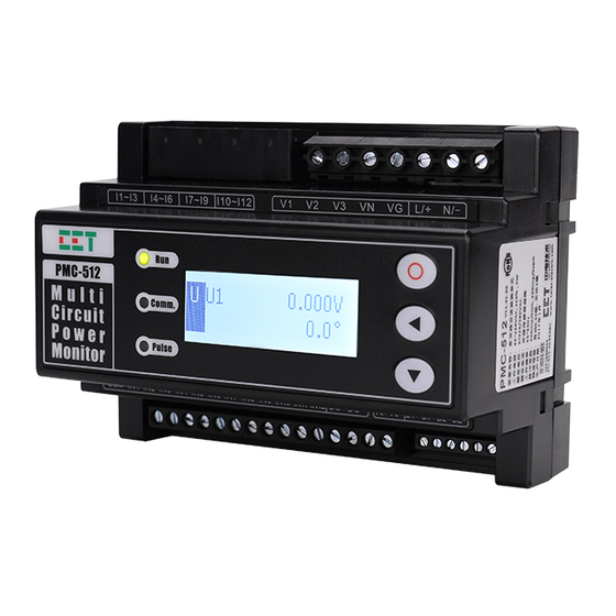
Figure 3-1 Front Panel of PMC-512-D Transducer Version Figure 3-2 Front Panel of PMC-512-D LCD Version 3.1 Front Panel LED Indicators There are three LED indicators on the PMC-512-D’s Front Panel as described in the following table. LED Indicator Color... -
Page 25: Front Panel Buttons
Table 3-2 Reset Mechanism for the PMC-512-D’s Transducer Version 3.2.2 Buttons on LCD PMC-512-D (Future) There are three buttons on the right-hand side of the PMC-512-D LCD Version, <O>, < > and < >. Their functions are described below. Button... -
Page 26: Data Display (Optional With The Future Lcd Version)
CET Inc. 3.3 Data Display (Optional with the Future LCD Version) The PMC-512-D’s LCD display defaults to the Auto-Scroll display mode where measurements in each of the selected Parameter Categories illustrated in Table 3-4 below are automatically scrolled through at a fixed 5-second interval. -
Page 27: Di/Do Status
Table 3-7 DI/DO Status Display Pages 3.3.5 SOE Log The PMC-512-D supports the display of the SOE Log with its relevant parameter values and its timestamp. The users can scroll through the SOE Log by pressing < > or < >. - Page 28 CET Inc. 3) Changing and saving a setup parameter: For a numeric parameter, press < > to shift the cursor to the left by one position or < > to increment the numeric value. For an enumerated parameter, press < > or < > to scroll backward and forward in the selection ...
-
Page 29: Setup Menu
CET Inc. 3.4.2 Setup Menu Figure 3-4 Setup Menu... -
Page 30: Configuration
CET Inc. 3.4.3 Configuration The Setup Configuration Mode provides access to the following setup parameters: Label Menu Description Range Default Setup Basic Nom. Voltage Nominal Voltage 48 V/240 V/336 V 240 V Mains Current Type Mains Current Type Incomer/Residual Incomer... - Page 31 CET Inc. H Delay Current H Alarm Delay 0 to 9999 (s) L Threshold Current L Alarm Threshold 0 to 100 (%) L Delay Current L Alarm Delay 0 to 9999 (s) LL Threshold Current LL Alarm Threshold 0 to 100 (%)
-
Page 32: Maintenance
Auto-Scroll Setup allows users to select which SM and whether Analog Input would be displayed in Auto-Scroll Mode. For Example, if the PMC-512-D is used for monitoring 9 branch circuits with SM1 to SM9, the remaining three SMs can be disabled in the Auto-Scroll Mode to prevent unnecessary information from being displayed. -
Page 33: Chapter 4 Applications
Table 4-1 Definition for DI Parameters Note: The available options for DI Excitation would depend on the PMC-512-D model. The 48VDC and -48VDC options are only available for the hardware that are equipped with 48VDC DI while the 220VDC, 220VAC, 110VDC and 110VAC options are available for the 240VDC (max. -
Page 34: Power, Energy And Demand
Demand is defined as the average power consumption over a fixed interval (usually 15 minutes) based on the sliding window method. The PMC-512-D provides the Current and kW Total Present Demand of Mains and Branch Circuits as well as the Current and kW total Peak Demand of Mains and Branch Circuits for This Month (Since Last Reset) and Last Month (Before Last Reset). -
Page 35: Alarm Setpoints
Table 4-5 Demand Setup 4.3 Alarm Setpoints The PMC-512-D provides powerful alarming functions for the Mains Meter, 12 Sub-Meters as well as different parameters. Each Alarm Type has an independent enable switch, which allows the alarms for Mains Meter, SM and other parameters to be enabled individually as needed. The alarms may also be disabled by setting their respective alarm thresholds to 0. -
Page 36: Voltage Alarms And On/Off Status
4.3.3 Voltage Alarms and ON/OFF Status PMC-512-D provides the Voltage ON/OFF status as well as two Voltage Alarm levels (High and Low) for the Mains Circuit. The Voltage H/L Alarms will only be evaluated if it’s determined that the Voltage... - Page 37 CET Inc. It should be noted that the absolute value of the Voltage ON/OFF Threshold is calculated based on the Nominal Voltage parameter. Therefore, it’s critical to set the Nominal Voltage correctly for the Voltage ON/OFF to work properly. Voltage Alarm ON Limit = Nominal Voltage x 5.0% Voltage Alarm OFF Limit = Voltage ON Limit x (1 –...
-
Page 38: Mains Current Alarms
CET Inc. 4.3.4 Mains Current Alarms PMC-512-D provides four Current alarm levels (High-High, High, Low, Low-Low) for the Mains Current. The Current Alarms will only be evaluated if it’s determined that the Current ON status is true for the Mains Meter. The Mains Current Alarms will only be evaluated if the Mains Current Type is Incomer. -
Page 39: Dc Residual Current Alarm
Figure 4-12 Current LL Alarm Logic Diagram 4.3.5 DC Residual Current Alarm When the Mains Current Type is Residual, the PMC-512-D provides 2 alarm levels (High-High, High) for the Residual Current Alarm. If the Mains Current Type is Incomer, the Residual Current Alarm is disabled. -
Page 40: Sm Current Alarm
Figure 4-14 Current HH Alarm Logic Diagram 4.3.6 SM Current Alarm PMC-512-D also provides four Current alarm levels (High-High, High, Low, Low-Low) for each SM Current. The SM Current Alarms will only be evaluated if it’s determined that the respective SM Current ON status is true. - Page 41 CET Inc. Notes: Bits 0 to 11 represent the SM Current Alarm Enable for SM1 to 12 respectively, with the bit value “0” meaning Disabled and “1” meaning Enabled. For example, 0x003F means SM1 to 6 are enabled for Current Alarm and SM7 to 12 are disabled.
-
Page 42: Ai Alarm
Figure 4-17 Current L Alarm Logic Diagram Current LL Alarm Figure 4-18 Current LL Alarm Logic Diagram 4.3.7 AI Alarm PMC-512-D provides four AI Alarm Levels (High-High, High, Low, Low-Low). The following table illustrates the AI Alarm parameters. Parameters Range... -
Page 43: Di Alarm
CET Inc. The logic diagram of AI H/HH Alarm is illustrated in Figure 4-19. Figure 4-19 AI H Alarm Logic Diagram The logic diagram of AI L/LL Alarm is illustrated in Figure 4-20. Figure 4-20 AI L Alarm Logic Diagram 4.3.8 DI Alarm... -
Page 44: Data Logging
Peak Demand can be reset individually through the Front Panel or via communications. 4.4.2 Monthly Energy Log The PMC-512-D stores monthly energy data of the Mains Meter and SMs for the present month and the last 24 months. The Monthly Energy Log Self-Read Time setup parameter allows the user to specify the time and day of the month for the Recorder’s Self-Read operation via communications. - Page 45 CET Inc. The Data Recorder Log is only operational when the values of Trigger Mode, Recording Mode, Recording Depth, Recording Interval, and Number of Parameters are all non-zero. The Recording Offset parameter can be used to delay the recording by a fixed time from the Recording Interval.
-
Page 46: Chapter 5 Modbus Register Map
0 if its current value is 0xFFFFFFFFH. The SOE Log capacity is relatively small with only 512 events in the PMC-512-D, and it can be reset to zero and then immediately incremented by one with a new “Clear SOE via Communications”... -
Page 47: Instantaneous Alarm
CET Inc. 5.1.2 Instantaneous Alarm Register Property Description Format Note 0030 Alarm#1 Status Bitmap 0031 Alarm#2 Status Bitmap 0032 Alarm#3 Status Bitmap 0033 Alarm#4 Status Bitmap 0034 Alarm#5 Status Bitmap Table 5-3 Instantaneous Alarm Note: For the Alarm #x Status register, each bit values of B0 to B11 represent different alarms, with “1” meaning active (Alarm) and “0”... -
Page 48: Latched Alarm
CET Inc. 5.1.3 Latched Alarm Register Property Description Format Note 0130 Alarm#1 Status Bitmap 0131 Alarm#2 Status Bitmap 0132 Alarm#3 Status Bitmap 0133 Alarm#4 Status Bitmap 0134 Alarm#5 Status Bitmap 0134~0145 Reserved Bitmap Table 5-9 Latch Alarm Note: For the Alarm #x Status register, each bit values of B0 to B15 represent different alarms, with “1” meaning active (closed) and “0”... -
Page 49: Basic Measurements
CET Inc. 5.2 Basic Measurements Register Property Description Format Scale Unit Bit 0: Voltage Bit 1: Mains I Bit 2: SM1 I … 0500 Channel Polarity UINT32 Bit 13: SM12 I Others: Reserved 0=Normal 1=Reverse 0502~0503 Reserved FP32 0504 FP32... -
Page 50: Demands
This Register represents the Month when it is read. To read the Monthly Energy Log, this register must be first written to indicate the PMC-512-D which log to load from memory. The range of this register is from 0 to 24, which represents the Present Month and the Last 24 Months. -
Page 51: Peak Demand Log Of This Month (Since Last Reset)
CET Inc. 5.5.2 Peak Demand Log of This Month (Since Last Reset) Register Property Description Format Scale Unit 4000 Mains Current Demand* FP32 4002 Timestamp UINT32 4004 SM1 Current Demand FP32 4006 Timestamp UINT32 4008 SM2 Current Demand FP32 4010... -
Page 52: Data Recorder Log
CET Inc. Offset Property Description Format Range/Note High-order Byte: Event Classification See Appendix A UINT16 Low-order Byte: Sub-Classification See Appendix A 0-99 (Year- High-order Byte: Year 2000) UINT16 Low-order Byte: Month 1 to 12 High-order Byte: Day 1 to 31... -
Page 53: Ai Setup
CET Inc. 4=1000 imp/kWh 5=3200 imp/kWh 6015 LED EN Pulse Mode UINT16 0* to 13 0=YYYY/MM/DD* 6016 Date Format UINT16 1=MM/DD/YYYY 2=DD/MM/YYYY 6017 Demo UINT16 0=Disabled*, 1=Enabled Table 5-24 Basic Setup Notes: The unit of Mains CT Primary is A for Mains Current or mA for Residual Current. -
Page 54: Alarm Setup
CET Inc. 5.7.5 Alarm Setup Register Property Description Format Range/Default* 6400 Universal Hysteresis UINT16 0 to 100 (x0.1%), 20* 6401 Current ON Threshold UINT16 0 to 100 (x0.1%), 50* 6402 Current ON Time Delay UINT16 0 to 9999 (s), 10s*... -
Page 55: Sm Setup Parameters
CET Inc. 6496 AI LL Alarm Time Delay UINT16 0 to 9999 (s), 10* 6497 AI Alarm Trigger UINT16 0* to 0x0003 Table 5-29 Alarm Setup Parameters Notes: ∣Alarm Threshold-Alarm Return Threshold∣ The calculation method for the Universal Hysteresis is listed below: Universal Hysteresis= ×%... -
Page 56: Data Recorder Setup
5.8 Time Registers There are two sets of Time registers supported by the PMC-PMC-512-D – Year / Month / Day / Hour / Minute / Second (Registers # 60000 to 60002) and UNIX Time (Register # 60004). When sending time to the PMC-512-D over Modbus communications, care should be taken to only write one of the two Time register sets. -
Page 57: Remote Control
Modbus Holding Registers (4XXXXX), which can be controlled with the Force Single Coil command (Function Code 0x05) or the Preset Multiple Hold Registers (Function Code 0x10). The PMC-512-D does not support the Read Coils command (Function Code 0x01) because DO Control registers are “Write- Only”. - Page 58 Value (Hex) ASCII 60200 9800 0x50 60201 9801 0x4D 60202 9802 0x43 60203 9803 0x2D 60204 9804 0x35 60205 9805 0x31 60206 9806 0x32 60207 9807 0x2D 60208 9808 0x44 60209-60219 9809-9819 0x20 <Null> Table 5-37 ASCII Encoding of “PMC-512-D”...
-
Page 59: Appendix A - Soe Event Classification
CET Inc. Appendix A - SOE Event Classification Event Sub- Event Channel Description Classification Classification Value DI1 Close/DI1 Open DI2 Close/DI2 Open DI3 Close/DI3 Open DI4 Close/DI4 Open DI5 Close/DI5 Open DI6 Close/DI6 Open DI7 Close/DI7 Open DI8 Close/DI8 Open... - Page 60 CET Inc. First Power On A/D Fault Internal Power Fault FRAM Fault FLASH Fault System Parameters Fault Internal Parameters Fault Note: The following table provides a detailed description of the Channel Number. Channel Number Description Invalid … … … …...
-
Page 61: Appendix B - Data Recorder Parameters
CET Inc. Appendix B - Data Recorder Parameters 1) SMs Group Structure Offset Description Current %Loading Current Demand kW total Demand SMs Real-time and Demand Measurement Description Description 37~42 7~12 43~48 13~18 49~54 19~24 55~60 SM10 25~30 61~66 SM11 31~36... -
Page 62: Appendix C - Technical Specifications
CET Inc. Appendix C - Technical Specifications Voltage Inputs Standard 240V Optional 48VDC Range 240V 0-400VDC (RMS), 0.05xUn-Umax 48VDC 0-60VDC (RMS), 0.05xUn-Umax Burden <0.05VA @240VDC Overload 1.2xUn continuous, 2xUn for 10s Current Inputs Mains Circuit Hall Effect Split-Core CTs 200A/400A/600A/800A/1000A/2000A Range 0.5% to 120% In... -
Page 63: Appendix D - Accuracy Specifications
CET Inc. Appendix D - Accuracy Specifications Parameters Accuracy Resolution Voltage ±0.5% 0.01V Current ±0.5% 0.001A Residual Current ±1.0% 0.01mA ±0.5% 0.001kW Class 0.5 (Main Unit) 0.01kWh Class 1.0 (including Hall Effect CT) Analog Input ±0.5%... -
Page 64: Appendix E - Standards Compliance
CET Inc. Appendix E - Standards Compliance Safety Requirements CE LVD 2014 / 35 / EU EN 61010-1: 2010, EN 61010-2-030: 2010 Electrical safety in low voltage distribution systems up IEC 61557-12: 2008 to 1000VAC and 1500 VDC Dielectric test:... -
Page 65: Appendix F - Ordering Guide
Appendix F - Ordering Guide... -
Page 66: Contact Us
CET Inc. Contact us CET Electric Technology Headquarters 8/F, Westside, Building 201, Terra Industrial & Tradepark, Che Gong Miao, Shenzhen, Guangdong, P.R.China 518040 Tel: +86.755.8341.5187 Fax: +86.755.8341.0291 Email: support@cet-global.com Web: www.cet-global.com...
Need help?
Do you have a question about the PMC-512-D and is the answer not in the manual?
Questions and answers