Table of Contents
Advertisement
Quick Links
Advertisement
Table of Contents

Related Manuals for CET PMC-690


Summary of Contents for CET PMC-690
- Page 1 PMC-690 Hand-Held Power Quality Analyzer User Manual Version: V1.0A Aug 27, 2018...
- Page 2 The information contained in this Manual is believed to be accurate at the time of publication; however, CET assumes no responsibility for any errors which may appear here and reserves the right to make changes without notice. Please consult CET or your local representative for latest product specifications.
- Page 3 CET Electric Technology DANGER Failure to observe the following instructions may result in severe injury or death and/or equipment damage. Installation, operation and maintenance of the meter should only be performed by qualified, competent personnel that have the appropriate training and experience with high voltage and current devices.
- Page 4 This warranty is on a return to factory for repair basis. CET does not accept liability for any damage caused by meter malfunctions. CET accepts no responsibility for the suitability of the meter to the application for which it was purchased.
-
Page 5: Table Of Contents
CET Electric Technology Table of Contents Table of Contents ............................5 Glossary ..............................8 Chapter 1 Introduction ..........................9 1.1 Overview ............................ 9 1.2 Features ............................9 1.3 Getting more information ......................13 Chapter 2 Installation ..........................14 2.1 Appearance ..........................14 2.2 Unit Dimensions ........................ - Page 6 CET Electric Technology 4.3.16 RMS Change Detection ....................42 4.4 Data Logging ..........................42 4.4.1 Device Log and SOE Log ....................42 4.4.2 Statistical Data Recorder (SDR) ..................42 4.4.3 Max./Min. Log ....................... 43 4.4.4 Pst Log ........................... 43 4.4.5 Plt Log ........................... 44 4.4.6 Waveform Recorder (WFR) ...................
- Page 7 CET Electric Technology 5.6.4 MM Log (Max./Min. Log) ....................65 5.6.5 Pst/Plt Log ........................66 5.6.6 EN50160 Log ......................... 66 5.7 Real-time WFR Register ......................71 5.8 Device Setup Parameters ......................72 5.8.1 Communications Setup ....................72 5.8.2 Basic Setup Parameters ....................72 5.8.3 SMTP Setup ........................
-
Page 8: Glossary
CET Electric Technology Glossary = Present Demand = Disturbance Waveform Recorder FIFO = First In First Out Fund. = Fundamental = Giga Byte = Global Positioning System = High-Speed = nth order Harmonic, integer multiple (n) of the Fundamental Frequency (50Hz or 60Hz) -
Page 9: Chapter 1 Introduction
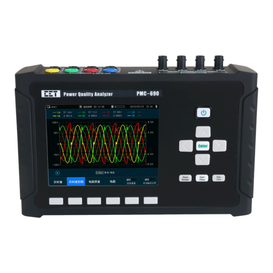
Chapter 1 Introduction This manual explains how to use the PMC-690 Advanced Power Quality Analyzer. This chapter provides an overview of the PMC-690 Analyzer and summarizes many of its key features. 1.1 Overview The PMC-690 Hand-Held Power Quality Analyzer is CET’s latest offer to assist engineers to diagnose the PQ events at site as it provides advanced functionality by combining Class 0.1 accuracy and advanced... - Page 10 CET Electric Technology Power Quality Features IEC 61000-4-30 Class A IEC 61000-4-7, IEC 61000-4-15 Transients, Dips, Swells, Interruptions, Rapid Voltage Changes (RVC) and In-rush Current monitoring Harmonic analysis up to 63 Disturbance Waveform Recording (DWR) ...
- Page 11 CET Electric Technology Harmonic and Interharmonic measurements K-Factor for Current, Crest Factor for Current and Voltage U and I THD, TOHD, TEHD rd # U and I Individual Harmonics (%HD) from 2 to 63 rd # U and I Individual Interharmonics (%IHD) from 1 to 63 ...
- Page 12 CET Electric Technology Max/Min Recorder (MMR) Log 4 records (20 parameters/recorder) with timestamp Logging of Max./Min. values for real-time measurements such as V, I, kW, kvar, kVA, PF, Freq., Unbalance, K-factor, THD Two log transfer modes: Manual: Max./Min. Since Last Reset/Before Last Reset Automatic: Max./Min.
-
Page 13: Getting More Information
Time Synchronization Battery-backed real-time clock @ 6ppm(≤ 0.5s/day) Time Sync. via Modbus SNTP 1.3 Getting more information Additional information is available from CET via the following sources: Visit www.cet-global.com Contact your local representative Contact CET directly via email or telephone... -
Page 14: Chapter 2 Installation
Chapter 2 Installation Caution Installation of the PMC-690 should only be performed by qualified, competent personnel that have the appropriate training and experience with high voltage and current devices. The meter must be installed in accordance with all local and national electrical codes. -
Page 15: Unit Dimensions
CET Electric Technology 2.2 Unit Dimensions Figure 2-2 Unit Dimensions 2.3 Wiring Connections Please read this section carefully before installation and choose the correct wiring method for your power system. The following wiring modes are supported: Single-Phase Connection ... -
Page 16: 3-Phase 3-Wire Delta Connection
CET Electric Technology Figure 2-3 Single-Phase 2-Wire Connection 2.3.2 3-Phase 3-Wire Delta Connection Please consult the serial number label to ensure that the Voltage and Current input is less than or equal to the meter’s input specification. Figure 2-4 3-Phase 3-Wire Delta Connection 2.3.3 3-Phase 4-Wire 2.5E-2PT Connection... -
Page 17: Ethernet Port (100Baset)
CET Electric Technology Figure 2-6 3-Phase 4-Wire Wye Connection 2.4 Ethernet Port (100BaseT) RJ45 Connector Meaning Transmit Data+ Transmit Data- Receive Data+ 4,5,7,8 Receive Data- Table 2-1 RJ45 Connector Pin Description for 100BaseT Applications 2.5 Chassis Ground Wiring Connect the Earthing Terminal to earth ground. -
Page 18: Chapter 3 Front Panel Interface
CET Electric Technology Chapter 3 Front Panel Interface The PMC-690 is equipped with a stunning, 640x480, TFT Color, LCD Display. The following figure illustrates PMC-690's Main Display, which is the first screen shown upon device power on. Figure 3-1 Main Display 3.1 Using the Front Panel Buttons... -
Page 19: Menu Tree
CET Electric Technology 3.2 Menu Tree The following figure illustrates menu tree of the Front Panel: Figure 3-3 Menu Tree... -
Page 20: Front Panel User Interface
CET Electric Technology 3.3 Front Panel User Interface The following table provides an overview of this display hierarchy. Category Topics Pages Real Time Metering PQ Insight Power Quality... - Page 21 CET Electric Technology Energy Demand Spectrum/Table Harmonics Power...
- Page 22 CET Electric Technology IH Spectrum IH Table Trend Trend/SDR Trend SOE Log Record Device Log Event Summary EN50160...
- Page 23 CET Electric Technology Max./Min. Basic Device Setup Storage...
- Page 24 CET Electric Technology Advanced...
- Page 25 CET Electric Technology New Site Switch Site Site Delete Site Rename Site Import Template Export Template...
- Page 26 CET Electric Technology Monitoring History Table 3-2 Description of each Hierarchy...
-
Page 27: Chapter 4 Applications
The predicted demand is typically used for pre-alarm and helps users reducing power consumption. PMC-690 also provides recording of Max. Demand of Present and last month. The PMC-690 has the following setup parameters which can set via communication or through the Front Panel: Setup Parameter... -
Page 28: Setpoints
Table 4-3 Demand Parameters 4.2 Setpoints The PMC-690 comes standard with 40 user programmable setpoints which provide extensive control by allowing a user to initiate an action in response to a specific condition. There are 24 Standard Setpoints and 16 High-Speed Setpoints. Typical setpoint applications include alarming, fault detection and power quality monitoring. - Page 29 CET Electric Technology Figure 4-2 Under Setpoint The Setpoints can be programmed over communications and have the following setup parameters: Setup Parameter Definition Options 0=Over Setpoint* Setpoint Type Specify the monitoring condition -- Over Setpoint, Under Setpoint. 1=Under Setpoint Setpoint Parameter Specify the parameter to be monitored.
-
Page 30: Power Quality Parameters
4.3 Power Quality Parameters 4.3.1 Power Frequency The PMC-690 is capable of measuring Frequency accurate to ±0.005Hz or 0.01%. The measurement range is ±15% of f , which is 40Hz to 60Hz for 50Hz system and 48 Hz to 72Hz for 60Hz system. -
Page 31: Supply Voltage Dips/Swells And Interruption
CET Electric Technology 4.3.4 Supply Voltage Dips/Swells and Interruption The PMC-690 supports the detection of the Supply Voltage Dips/Swells and Interruption using a method that is in accordance with Section 5.4 of IEC 61000-4-30 Standard for Class A performance. The PMC-690 provides Dip/Swell and Interruption detection for voltage quality monitoring on a per phase basis and records an event in the SOE Log, which includes the event timestamp, event type, event characteristics and ITIC/SEMI F47 curve. -
Page 32: Voltage Interruptions
Figure 4-4 WFR of a Dip Event 4.3.5 Voltage Interruptions The PMC-690 supports the detection of Voltage Interruptions using a method that is in accordance with Section 5.5 of IEC 61000-4-30 Standard for Class A performance. 4.3.5.1 Voltage Interruption Evaluation... -
Page 33: Voltage Transients
IEC 61000-4-30 with a maximum resolution of 40µs (@50Hz) for the standard. The PMC-690 provides transient detection for voltage quality monitoring and records an event in the SOE Log, which includes the event timestamp event type, and event characteristics. In addition, transient would trigger WFR, DWR and RMS Recorder. -
Page 34: Supply Voltage Unbalance
CET Electric Technology 4.3.7 Supply Voltage Unbalance The PMC-690 provides both the Zero Sequence and Negative Sequence Voltage and Current Unbalance measurements using Symmetrical Components and in accordance with Section 5.7 of IEC 61000-4-30 Standard for Class A performance. (Negative Sequence Unbalance) ... - Page 35 ▪ ▪ ▪ ▪ ▪ ▪ Table 4-12 Voltage and Current Harmonics and Interharmonics Measurements 4.3.8.2 Power Harmonics The following table illustrates the Power Harmonic measurements available on the PMC-690: kW/kvar/kVA TH ▪ ▪ ▪ ▪ ▪ ▪ PF TH kW/kvar/kVA Fundamental ▪...
-
Page 36: Mains Signalling Voltage (Msv)
120s. The PMC-690 provides 3 groups of waveform recorder for MSV in accordance with Section 5.10 of IEC 61000-4-30 Standard for Class A performance. Each MSV WR will be recorded in SOE Log and EN50160 report. -
Page 37: Rapid Voltage Changes (Rvc)
The characteristic parameter of the rapid voltage change is the difference between the steady-state value reached after the change and the initial steady-state value. The PMC-690 provides the ability to capture RVC in accordance with the IEC 61000-4-30 Standard and records in SOE Log and High-speed Recording with event timestamp, event type, and event characteristics. -
Page 38: Inrush Current
CET Electric Technology example, the voltage tolerance is 0.5% that is the allowable fluctuation max voltage is 0.005Vll nominal. Steady-State Duration Duration to reach the steady-state condition. 1 to 50 (x0.1s), 10* Minimum voltage step change between two steady-state Min. of V Change Step 1 to 1000 (x0.001Udin), 50*... -
Page 39: Flagging Concept
The PMC-690 is a certified IEC 61000-4-30 Class A device so it supports the Flagging Concept. Flagging Setup... -
Page 40: En50160 Compliance Report
For a complete definition of the non-conformity level for each of the following EN50160 parameters, please refer to the EN50160 Standard document. The PMC-690 can measure, summarize data and statistics relevant data in accordance with the EN50160 standard. In addition, the device is capable of creating a report per week for the following PQ parameters and the report can be stored for one year. -
Page 41: Itic/Semi F47 Curve
PMC-690’s Front Panel can display ITIC or SEMI F47 curve for PQ Events. Navigate to SOE Log page in the Front Panel, move cursor to curve in the Front Panel to display ITIC or SEMI F47 curve. -
Page 42: Rms Change Detection
4.4 Data Logging 4.4.1 Device Log and SOE Log The PMC-690’s Device Log and SOE Log can store up to 1024 events in its non-volatile memory. The Device Log consists of such events as power-on, power-off, sites management and setup changes for... -
Page 43: Max./Min. Log
Table 4-24 Setup Parameters for Max./Min. Log 4.4.4 Pst Log The PMC-690’s Pst Log can store up to 52560 events per 10 minutes about voltage Pst in its non-volatile memory. Each event record includes the event classification, its relevant parameter values and a timestamp in 1ms resolution. -
Page 44: Plt Log
CET Electric Technology 4.4.5 Plt Log The PMC-690’s Plt Log can store up to 4380 events per 2 hours about voltage Plt in its non-volatile memory. Each event record includes the event classification, its relevant parameter values and a timestamp in 1ms resolution. -
Page 45: Rms Log
Figure 4-13 Disturbance Waveform Recorder 4.4.8 RMS Log The PMC-690’s RMS Log can store up to 500 events for each monitoring site in its non-volatile memory. The RMS Log records RMS @1/2 cycle for parameters including 3-phase Voltage and 3-phase Current. -
Page 46: Trend And Sdr Trend
COMTRADE format in its 16GB removable SD card. All record can be stored for about half a year and will not suffer any loss in the event of a power failure. The PMC-690 can store following standard data with PQDIF format. -
Page 47: Pq Counters
4.5 Site Management and Monitoring The PMC-690 provides function of managing up to 8 sites that is capable of recording and saving a maximum of 50 monitoring records each in the device non-volatile memory. Users just need to load the sites information and parameters that are configured before testing and therefore greatly improve the efficiency. -
Page 48: Time Synchronization
Figure 4-18 Setup Start/End Mode for Sites via Front Panel 4.6 Time Synchronization The PMC-690 provides timestamps for all recorded data so it's extremely important for the clock to be properly configured to achieve precise events time stamping for energy and power quality analysis. -
Page 49: Sntp
PC for establishing a connection. 4.7.2 USB Port The PMC-690 comes standard with an USB port for data transfer to the USB storage device. After inserting a reliable USB drive into the USB port, the system would detect the drive and users can transfer data, waveform logs as well as event logs via the user friendly interface in the Front Panel. - Page 50 CET Electric Technology Max. Demand of Last Time /data/site/site n/20230414_071155/Demand/last Energy /data/site/site n/20230414_071155/Energy Max. /data/site/site n/20230414_071155/Max Min. /data/site/site n/20230414_071155/Min Pst Log /data/site/site n/20230414_071155/pst/ Plt Log /data/site/site n/20230414_071155/plt/ EN50160 /data/site/site n/20230414_071155/EN50160 PQDIF /data/site/site n/20230414_071155/PQDIF/ PQDIF Internal DR /data/site/site n/20230414_071155/pqdifStatRecord/... Site Events...
-
Page 51: Chapter 5 Modbus Register Map
Chapter 5 Modbus Register Map This chapter provides a complete description of the Modbus register map (Protocol Version 3.0) for the PMC-690 Advanced Utility Power Quality Analyzer to facilitate the development of 3 party Modbus RTU communications driver for accessing information on the PMC-690. - Page 52 CET Electric Technology 0078 Plt Timestamp - Millisecond UINT32 0080 Flagging Status of Real-time Data Bitmap 0081~0092 Reserved 0093 Standard Setpoint Status Bitmap 0095~0109 Reserved Bitmap 0111 HS Setpoint Status Bitmap 0113 Reserved 0115 Dips Counter UINT32 0117 Swells Counter...
-
Page 53: Energy Measurements
Device / SOE Log generated and will roll over to 0 if its current value is 0xFFFFFFFF. Since the Device /SOE Log Pointer is a 32-bit value and the Device / SOE Log capacity is relatively small with only 1024 entries in the PMC-690, an assumption has been made that the Device / SOE Log pointer will never roll over. -
Page 54: Harmonics & Interharmonic Measurements
CET Electric Technology 0750 U0 Unbal. Float 0752 U2 Unbal. Float 0754 I0 Unbal. Float 0756 I2 Unbal. Float 0758 Float 0760 Float 0762 Float 0764 Float 0766 Float 0768 Float 0770 Ua (WYE) / Uab (Delta) Pst Float 0772... -
Page 55: Harmonic Voltage & Current Rms
CET Electric Technology 1012 Ic THD Float % / x100 1014 I4 THD Float % / x100 1016 Reserved Float % / x100 1018 Ua (WYE) / Uab (Delta) TOHD Float % / x100 1020 Ub (WYE) / Ubc (Delta) TOHD... -
Page 56: Individual Total Harmonic
CET Electric Technology 2326 Ia TOH01 RMS Float 2328 Ib TOH01 RMS Float 2330 Ic TOH01 RMS Float 2332 I4 TOH01 RMS Float 2334 Reserved Float 2336 Ua (WYE) / Uab (Delta) TEH01 RMS Float 2338 Ub (WYE) / Ubc (Delta) TEH01 RMS... -
Page 57: Harmonic Power
CET Electric Technology 5.4.4 Harmonic Power Register Property Description Format Unit 28000 Float 28002 Float 28004 Float 28006 kW Total TH Float 28008 kvara Float 28010 kvarb Float 28012 kvarc Float 28014 kvar Total TH Float 28016 kVAa Float 28018... -
Page 58: Harmonic Energy
CET Electric Technology 31142 Ia Angle H63 Float 31144 Ib Angle H63 Float 31146 Ic Angle H63 Float 31148 I4 Angle H63 Float 31150 Reserved Float Table 5-11 Harmonic Angle 5.4.6 Harmonic Energy Register Property Description Format Unit 31500 kWh Imp. TH... -
Page 59: Interharmonic Voltage & Current Rms
CET Electric Technology 33136 Ua (WYE) / Uab (Delta) TEIHD Float %, x100 33138 Ub(WYE) / Ubc(Delta) TEIHD Float %, x100 33140 Uc (WYE) / Uca (Delta) TEIHD Float %, x100 33142 U4 TEIHD Float %, x100 33144 Ia TEIHD... -
Page 60: Demand
CET Electric Technology 34562 Ia IH00 RMS Float 34564 Ib IH00 RMS Float 34566 Ic IH00 RMS Float 34568 I4 IH00 RMS Float 34570 Reserved Float 34572 Ua (WYE) / Uab (Delta) IH01 RMS Float 34574 Ub (WYE) / Ubc (Delta) IH01 RMS... - Page 61 CET Electric Technology 3670 P.F.a Float 3672 P.F.b Float 3674 P.F.c Float 3676 P.F. Total Float 3678 Freq Float 3680 Ua Deviation Float 100% 3682 Ub Deviation Float 100% 3684 Uc Deviation Float 100% 3686 Uab Deviation Float 100% 3688...
-
Page 62: Predicted Demand
CET Electric Technology Notes: When the Wiring Mode is Delta, the phase voltages demand, kWs demand, kvars demand and kVAs demand have no meaning, and their registers are reserved. 5.5.2 Predicted Demand Register Address Property Description Format Unit 3900 Float... -
Page 63: Max. Of Last Time
* Writing n to the Device Log Pointer register will update the Device Log Buffer with Device Log Events from pointer positions from n to n+9. Table 5-22 Device Log Buffer Notes: The PMC-690’s Device Log can store up to 1024 events, if there are more than 1024 events, the newest event will replace the oldest event on a FIFO basis. -
Page 64: Soe Log Buffer
* Writing n to the SOE Log Pointer register will update the SOE Log Buffer with SOE Log Events at pointer positions from n to n+9. Table 5-24 SOE Log Buffer Note: The PMC-690’s SOE Log can store up to 1024 events and if there are more than 1024 events, the latest event will replace the oldest event on a FIFO basis. Offset... -
Page 65: Mm Log (Max./Min. Log)
CET Electric Technology +510~+517 Data Item #64 * Writing n to the SDR Log X Pointer register will update the SDR Log X Buffer with the SDR Log X Record at pointer position n. Table 5-27 SDR Log Buffer Structure Notes: The data items can be configured as any real-time data. -
Page 66: Pst/Plt Log
CET Electric Technology Month Hour Minute Second +3~+4 Max. or Min. Value Table5-32 MM Data Item Data Structure Notes: The formats of data Items are defined in Appendix A. For example, the Parameter#1 number is set to 10001, the statistical records data item # 1’s data type (register address 35800) is automatically updated to 6, represents a 32-bit floating-point... - Page 67 CET Electric Technology 24216 Freq Wide Conclusion UINT32 0=Pass, 1=Failed Number of valid intervals in which the freq deviates from 24218 Freq N2 UINT32 the nominal by more than user defined wide limit 24220 Freq (1 - N2/N) Float 24222...
- Page 68 CET Electric Technology 24322 U Unbalance (1 - N1/N) Float 24324 U Unbalance Max. Float Maximum/Minimum/CP95 24326 U Unbalance Min. Float voltage unbalance value over 1 week 24328 U Unbalance CP95 Float 24320 Harmonic Conclusion UINT32 0=Pass, 1=Failed 24332 Harmonic N Valid...
- Page 69 CET Electric Technology 25202 Ub H25 CP95 Float 25204 Uc H25 CP95 Float 25206~25216 Reserved Float 25218 Ua H02 Avg Float 25220 Uc H02 Avg Float 25222 Uc H02 Avg Float · · · · · · Float 25356 Ua H25 Avg...
- Page 70 CET Electric Technology … · · · 26048 MSV3 Conclusion UINT32 26050 Ua MSV3 N1 UINT32 26052 Ub MSV3 N1 UINT32 26054 Uc MSV3 N1 UINT32 26056 Ua MSV3 (1 - N1/N) Float 26058 Ub MSV3 (1 - N1/N) Float...
-
Page 71: Real-Time Wfr Register
CET Electric Technology 26180 Dip N22 UINT32 26182 Dip N32 UINT32 26184 Dip N42 UINT32 26186 Dip N52 UINT32 26188 Dip N62 UINT32 26190 Dip N13 UINT32 26192 Dip N23 UINT32 26194 Dip N33 UINT32 26196 Dip N43 UINT32 26198... -
Page 72: Device Setup Parameters
CET Electric Technology … … Float 54030 Ia 512 Sample Float 54032 Ib 1 Sample Float … … Float 55054 Ib 512 Sample Float 55056 Ic 1 Sample Float … … Float 56078 Ic 512 Sample Float 56080 Ua 1... -
Page 73: Smtp Setup
CET Electric Technology 41031 Order of Harmonic Calculation UINT16 2 to 63* 41032~41033 Reserved 0*=5A (50A) @10mV/A 1=20A@10mV/A 2=200A@1mV/A 41035 CT Clamp Specification UINT16 3=500A @1mV/A 4=500A(550A) @1mV/A 5=5kA @0.1mV/A 41036 Frequency UINT16 0=50Hz*, 1=60Hz *Default Table 5-43 Basic Setup Parameters Notes: The CT Polarity register defines the polarity for the Current Inputs as illustrated in the following table. -
Page 74: Pq Setup
This string parameter may be up to 10 characters long and specifies the Logon Password to login the “Source Email” account. For example, if the password is “PMC-690”, set the parameter as “50 4D 43 2D 36 38 30 69 00 00” where the two zero characters “00 00”... -
Page 75: Pqdif Setup
CET Electric Technology 41154 MSV #1 Enable UINT16 0=Disabled*, 1=Enabled 50 Hz: 600 to 30000 (x0.1Hz) 41155 MSV #1 Frequency UINT16 60 Hz: 700 to 30000 (x0.1Hz) Default=10000 3 to 1000 (x0.001Udin) 41156 MSV #1 Limit UINT16 Default=50 (x0.001Udin) 41157... -
Page 76: Demand Setup
CET Electric Technology 0 to 1* Hour 41204 PQDIF Save Interval UINT16 0 Indicates PQDIF is disabled *Default Table 5-49 PQDIF Setup 5.8.6 Demand Setup Register Address Property Description Format Range / Options 41250 Demand Sync. UINT16 0=SLD* 41251 Demand Period... -
Page 77: Hs (High-Speed) Setpoints Setup
0* to 9999 s 41708 Trigger UINT32 0=Disabled* 41710 Reserved *Default Table 5-52 Setpoint Setup Parameters Notes: The PMC-690 provides the following setpoint parameters: Parameter Parameter Parameter ULN* U TEHD kW Exp. Total Demand ULL* I THD kvar Exp. Total Demand... -
Page 78: Sdr Setup
CET Electric Technology 45595 Parameter UINT32 See Table 5-53 above 0=Disabled* 45597 Type UINT16 1=Over Setpoint 2=Under Setpoint 45598 Active Limit Float Default=0 HS Setpoint 45600 Inactive Limit Float Default=0 45602 Active Delay UINT16 0* to 9999 cycle 45603 Inactive Delay... - Page 79 CET Electric Technology 5.8.10.2 SDR #2 Setup Register Property Description Format Range/Options Default 46000 Recording Interval UINT16 0 to 60 min 0=Stop-When-Full 46001 Recording Mode UINT16 1=First-In-First-Out 46002 Number of Parameters UINT16 0 to 64 46003 Parameter #1 UINT16 Ua HD00...
- Page 80 CET Electric Technology 46062 Parameter #60 UINT16 U4 HD14 10559 46063 Parameter #61 UINT16 Ua HD15 10560 46064 Parameter #62 UINT16 Ub HD15 10561 46065 Parameter #63 UINT16 Uc HD15 10562 46066 Parameter #64 UINT16 U4 HD15 10563 Table 5-57 SDR #2 Setup 5.8.10.3 SDR #3 Setup...
-
Page 81: Max./Min. Recorder (Mmr) Setup
CET Electric Technology 46155 Parameter #53 UINT16 Ua HD29 10616 46156 Parameter #54 UINT16 Ub HD29 10617 46157 Parameter #55 UINT16 Uc HD29 10618 46158 Parameter #56 UINT16 U4 HD29 10619 46159 Parameter #57 UINT16 Ua HD30 10620 46160 Parameter #58... - Page 82 CET Electric Technology 49010 49410 Parameter #9 UINT16 Uc Under Deviation 10047 49011 49411 Parameter #10 UINT16 Uab Under Deviation 10048 49012 49412 Parameter #11 UINT16 Ubc Under Deviation 10049 49013 49413 Parameter #12 UINT16 Uca Under Deviation 10050 49014...
-
Page 83: En50160 Setup
CET Electric Technology Notes: The Self-Read Time supports the following two options: A zero value means that the Self-Read will take place at 00:00 of the first day of each month. A non-zero value means that the Self-Read will take place at a specific time and day based on the formula: Self-Read Time = (Day x 100 + Hour) where 0 ≤... -
Page 84: Trend Log Setup
Table 5-63 EN50160 Parameters Setup 5.8.13 Trend Log Setup The Trend Log is displayed on the PMC-690's Front Panel Interface. Up to 12 parameters can be displayed at the same time. The Trend Log parameters must be part of the SDR Log. -
Page 85: Time Registers
5.9 Time Registers There are two sets of Time registers supported by the PMC-690 - Year / Month / Day / Hour / Minute / Second (Registers # 60000 to 60002 for 6-digit addressing and Registers # 9000 to 9002 for 5-digit addressing) and UNIX Time (Registers # 60004 to 600005 for 6-digit addressing and Registers # 9004 to 9005 for 5-digit addressing). -
Page 86: Information
9850 Remaining Memory UNIT16 Units: MB Table 5-69 Meter Information Notes: The Meter Model appears in registers 60200 to 60219 and contains the ASCII encoding of the string “PMC-690” as shown in the following table. Offset Address Value(Hex) ANSCII 60200... -
Page 87: Device Tag Information
Char Devtag 2 40690 Voltage Level Char Devtag 3 Table 5-71 Device Tag Information Notes: However, the PMC-690's Front Panel Interface supports the display of up to 39 characters only. 5.10.3 Circuit Tag Information Register Property Description Format Note 52000... -
Page 88: Appendix A - Data Id
CET Electric Technology Appendix A - Data ID SDR Data ID Key ID Parameters 50-cycle 150-cycle 10-min 2-hour 10001 20001 30001 FREQ 10002 20002 30002 10003 20003 30003 10004 20004 30004 10005 20005 30005 10006 20006 30006 Uln Avg. 10007... - Page 89 CET Electric Technology 10059 20059 30059 10060 20060 30060 10061 20061 30061 10062 20062 30062 10063 20063 30063 10064 20064 30064 10065 20065 30065 Ia TDD 10066 20066 30066 Ib TDD 10067 20067 30067 Ic TDD 10068 20068 30068 I4 TDD...
- Page 90 CET Electric Technology 10125 20125 30125 Ia TEHD 10126 20126 30126 Ib TEHD 10127 20127 30127 Ic TEHD 10128 20128 30128 I4 TEHD 10129 20129 30129 Reserved 10130 20130 30130 Uab Fund. 10131 20131 30131 Ubc Fund. 10132 20132 30132 Uca Fund.
- Page 91 CET Electric Technology 1092 11092 21092 31092 Reserved 1093 11093 21093 31093 Ia TOH RMS 1094 11094 21094 31094 Ib TOH RMS 1095 11095 21095 31095 Ic TOH RMS 1096 11096 21096 31096 I4 TOH RMS 1097 11097 21097 31097...
- Page 92 CET Electric Technology 1682 11682 21682 31682 kvara TH 1683 11683 21683 31683 kvarb TH 1684 11684 21684 31684 kvarc TH 1685 11685 21685 31685 kVAa TH 1686 11686 21686 31686 kVAb TH 1687 11687 21687 31687 kVAc TH 1688...
- Page 93 CET Electric Technology 1985 11985 21985 31985 kWc H02 1986 11986 21986 31986 kvara H02 1987 11987 21987 31987 kvarb H02 1988 11988 21988 31988 kvarc H02 1989 11989 21989 31989 kVAa H02 1990 11990 21990 31990 kVAb H02 1991...
- Page 94 CET Electric Technology 3013 13013 23013 33013 I4 IHD00 3014 13014 23014 33014 Reserved 3015 13015 23015 33015 Ia IHD01 3016 13016 23016 33016 Ib IHD01 3017 13017 23017 33017 Ic IHD01 3018 13018 23018 33018 I4 IHD01 3019 13019...
-
Page 95: Demand Data Id
CET Electric Technology 3930 13930 23930 33930 Ic IH63 RMS 3931 13931 23931 33931 I4 IH63 RMS 3932 13932 23932 33932 Reserved 3933 13933 23933 33933 Ua Angle 3934 13934 23934 33934 Ub Angle 3935 13935 23935 33935 Uc Angle... - Page 96 CET Electric Technology 51008 51043 Uc Dev. 51078 Ua TOHD 51009 Ull Avg. 51044 Uab Dev. 51079 Ub TOHD 51010 51045 Ubc Dev. 51080 Uc TOHD 51011 51046 Uca Dev. 51081 U4 TOHD 51012 51047 Ua Over Dev. 51082 Ia TOHD 51013 I Avg.
-
Page 97: Appendix B - Event Classification
CET Electric Technology Appendix B - Event Classification Device Event Classification Event Sub- Description Value Scale/Option Classification Classification Power On None Power Off None Change System Parameters None Change Secret Parameters None 0= Set Clock via Front Panel Set Clock... -
Page 98: Soe Log Classification
CET Electric Technology WFR Triggered by High-speed Setpoint UNIT32: HS Setpoint Number Reserved WFR Triggered by Rapid Voltage Changes None WFR Triggered by Inrush Current None Triggered WFR Manually None Triggered WFR by Timer UNIT32: 0~7=Sub RMS Change DWR Triggered by RMS Change... - Page 99 CET Electric Technology UINT32: Location 0=UpStream, 1=DownStream Dips Location Detective UINT32: Reliability 0=Low, 1=Middle, 2=High FP32: Disturbance Max./Min. (%) UINT32: Duration (μs) 0X82: Transient Voltage Transient FP32: Ua Disturbance (%) FP32: Ub Disturbance (%) FP32: Uc Disturbance (%) Inrush Ia Active...
-
Page 100: Appendix C - Technical Specifications
CET Electric Technology Appendix C - Technical Specifications Voltage Inputs (CH1, CH2, CH3, CH4) Voltage Range 5V to 600V Burden <0.1VA per phase PT Ratio Primary 1-1,000,000V Secondary 1-690V V4 Primary 1-1,000,000V V4 Secondary 1-400V Frequency 40Hz-60Hz @ 50Hz 48Hz-72Hz @ 60Hz... -
Page 101: Appendix D - Accuracy Specifications
CET Electric Technology Appendix D - Accuracy Specifications Parameters Accuracy Resolution Voltage ±0.1% 0.01V Current ±0.1% + CT Clamps Accuracy 0.001A kW, kVA ±0.2% + CT Clamps Accuracy 0.001kX kWh, kVAh IEC 62053-22 Class 0.5S 0.1kXh kvar ±0.2% + CT Clamps Accuracy 0.001kvar... -
Page 102: Appendix E - Standards Compliance
CET Electric Technology Appendix E - Standards Compliance Power Quality Voltage characteristics of electricity supplied by public EN 50160 distribution systems General guide on harmonics and interharmonics measurements and instrumentation, for power supply systems and equipment IEC 61000-4-7 connected thereto... -
Page 103: Contact Us
CET Electric Technology Contact us CET Inc. 8/F, Westside, Building 201, Terra Industrial & Tradepark, Che Gong Miao, Shenzhen, Guangdong, P.R.China 518040 Tel: +86.755.8341.5187 Fax: +86.755.8341.0291 Email: sales@cet-global.com Web: www.cet-global.com...
Need help?
Do you have a question about the PMC-690 and is the answer not in the manual?
Questions and answers