Table of Contents
Advertisement
Advertisement
Table of Contents

Related Manuals for CET PMC-340


Summary of Contents for CET PMC-340
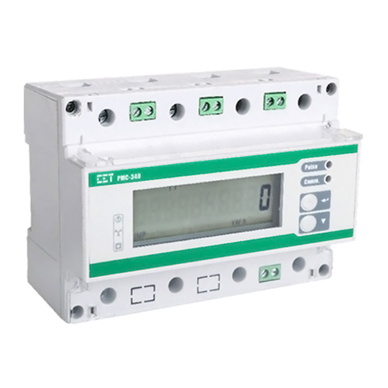
- Page 1 PMC-340 Digital Three-Phase Energy Meter User Manual Version: V1.1A May 8, 2018...
- Page 2 The information contained in this manual is believed to be accurate at the time of publication; however, CET assumes no responsibility for any errors which may appear here and reserves the right to make changes without notice. Please consult CET or your local representative for the latest product specifications.
- Page 3 CET Inc. DANGER Failure to observe the following instructions may result in severe injury or death and/or equipment damage. Installation, operation and maintenance of the meter should only be performed by qualified, competent personnel that have the appropriate training and experience with high voltage and current devices. The meter must be installed in accordance with all local and national electrical codes.
- Page 4 This warranty is on a return to factory for repair basis. CET does not accept liability for any damage caused by meter malfunctions. CET accepts no responsibility for the suitability of the meter to the application for which it was purchased.
-
Page 5: Table Of Contents
Table of Contents Chapter 1 Introduction ........................8 1.1 Overview..........................8 1.2 Features ..........................8 1.3 PMC-340’s application in Power and Energy Management Systems ....... 10 1.4 Getting more information ....................11 Chapter 2 Installation ........................12 2.1 Appearance ........................12 2.2 Unit Dimensions ........................ - Page 6 CET Inc. 4.4.4 SOE Log (PMC-340B Only) ..................28 4.4.5 Data Recorder Log (PMC-340B Only) ..............28 4.5 Time of Use (TOU) ......................29 Chapter 5 Modbus Register Map ....................... 31 5.1 Basic Measurements ......................31 5.2 Energy Measurements ...................... 33 5.2.1 3-Phase Energy Measurements ................
- Page 7 CET Inc. Appendix D Ordering Guide ......................57 Contact us ............................58...
-
Page 8: Chapter 1 Introduction
DIN rail mount, high accuracy, multifunction measurements and a large, easy to read LCD display. The PMC-340 complies with the IEC 62053-21 Class 1 and IEC 62053-22 Class 0.5S kWh Accuracy Standards for 100A Direct Input and 5A CT Input, respectively. The PMC-340 comes standard with a LED as well as a Solid State Pulse Output for energy pulsing. - Page 9 CET Inc. Per Phase Current Demands and Max. Demands Max./Min. Log Two TOU schedules, each providing 12 Seasons 20 Daily Profiles, each with 12 Periods in 15-minute interval 90 Holidays or Alternate Days 4 Tariffs, each providing the following information kWh/kvarh Imp/Exp, kVAh kW/kvar/kVA Max.
-
Page 10: Pmc-340'S Application In Power And Energy Management Systems
RS-485 Port 1.3 PMC-340’s application in Power and Energy Management Systems The PMC-340 series meter can be used to monitor Wye connected power system. Modbus communications allow real-time data and other information to be transmitted across a RS-485 network... -
Page 11: Getting More Information
CET Inc. 1.4 Getting more information Additional information is available from CET via the following sources: Visit www.cet-global.com Contact your local representative Contact CET directly via email at support@cet-global.com... -
Page 12: Chapter 2 Installation
Chapter 2 Installation Caution Installation of the PMC-340 should only be performed by qualified, competent personnel that have the appropriate training and experience with high voltage and current devices. The meter must be installed in accordance with all local and national electrical codes. -
Page 13: Terminal Dimensions
Move the installation clips at the back of the PMC-340 downward to the “unlock” position Align the top of the mounting channel at the back of the PMC-340 at an angle against the top of the DIN rail as shown in Figure 2-4 below ... -
Page 14: Wiring Connections
CET Inc. 2.5 Wiring Connections The PMC-340 supports 100A Direct Input or 5A CT Input. Please read this section carefully before installation and choose the correct wiring method for your power system. 2.5.1 Direct Input Wiring 3P3W 3P4W 1P3W 1P2W L-L* 1P2W L-N* * The wiring modes 1P2W L-N and 1P2W L-L are not supported by PMC-340A. -
Page 15: Rs-485 Wiring
Figure 2-6 CT Input connections 2.6 RS-485 Wiring The PMC-340 provides one standard RS-485 port that supports the Modbus RTU protocol. Up to 32 devices can be connected on a RS-485 bus. The overall length of the RS-485 cable connecting all devices should not exceed 1200m. -
Page 16: Chapter 3 Front Panel
The meter’s LCD display and two buttons are used for both data display and setup configuration purposes. Figure 3-1 Front Panel Display 3.1 LED Indicator There are two LED indicators on the PMC-340’s front panel as described below: LED Indicator Description Pulse LED Energy Pulse Output Comm. -
Page 17: Lcd Display
LCD Test mode. 3.5 Default Display The PMC-340 has a Default Display that shows the kWh Imp parameter under the Energy menu as shown below. The user can use the <↩> and <▼> buttons to scroll and display other parameters. -
Page 18: Setup Configuration
Ia THD Ib THD Ic THD dI CoUnTer (DI Counter) Table 3-4 PMC-340 Data Display Pages Notes: 1) When the Wiring Mode is 3P3W or 1P2W L-L, the phase A/B/C Voltage THD/TOHD/TEHD/HDxx is phase AB/BC/CA Voltage THD/TOHD/TEHD/HDxx. 3.6 Setup Configuration 3.6.1 Functions of buttons... - Page 19 CET Inc. Configuration. Once inside Setup Configuration, pressing <↩> either enters a sub- menu or selects a parameter for modification. If inside a sub-menu, pressing <↩> for two seconds will return to the main menu. If a parameter is selected, its value will blink while it’s being changed.
-
Page 20: Setup Menu
CET Inc. 3.6.2 Setup Menu Figure 3-4 Setup Menu 3.6.3 Configuration The Setup Configuration mode provides access to the following setup parameters: Label Description Range Default Menu Main ProGrAM Setup Configuration Enter Password 0 to 9999 SET PW Set New Password... - Page 21 Counter for Important Setup Parameter CCnT Changes via Communications Table 3-3 Setup Parameters Notes: The wiring modes 1P2W L-N and 1P2W L-L are not supported by PMC-340A. This screen only appears if the PMC-340 is equipped with CT Inputs. Power Factor Convention...
- Page 22 CET Inc. Figure 3-5 PF Convention There are two ways to calculate kVA: Mode V (Vector method): Mode S (Scalar method): PPS: 1 Pulse Per Second. DMD: 1 pulse is generated at the end of every Demand Interval. Tariff Switch: 1 pulse is generated every time a Tariff Switch takes place based on TOU Schedule.
-
Page 23: Chapter 4 Applications
Table 4-1 DI Setup Parameters 4.1.2 Energy Pulse Output The PMC-340 comes standard with one front panel LED Pulse Output and one Solid State Relay Output for energy pulsing. Energy Pulse Output is typically used for accuracy testing. Energy Pulsing can be enabled from the front panel through the Energy Pulse setup parameter. -
Page 24: Power And Energy
CET Inc. 4.2 Power and Energy 4.2.1 Basic Measurements The PMC-340 provides the following basic measurements which can be retrieved via the Front panel or communication: Parameter Phase A Phase B Phase C Total Average ● ● ● ● ●... -
Page 25: Power Quality
4.3.2 Power Quality Parameters The PMC-340 provides the following PQ parameters: 4.3.2.1 Harmonics The PMC-340 provides THD, TOHD, TEHD and individual harmonics up to the 31 order. All harmonic parameters are available through communication while THDs are available on the front panel display. -
Page 26: Unbalance
Harmonics Harmonics Harmonics … Harmonic Harmonic Harmonic Table 4-6 Harmonic Measurements 4.3.3 Unbalance The PMC-340 provides Voltage and Current Unbalance measurements. The calculation method of Voltage and Current Unbalance are listed below: Voltage Unbalance = 100% Current Unbalance =... -
Page 27: Logging
4.4 Logging 4.4.1 Max./Min. Log The PMC-340 records the Max. Log and Min. Log of This Month (Since Last Reset) and Last Month (Before Last Reset) with timestamp for 44 parameters. Each log includes the relevant parameter value and its timestamp. The recorded data is stored in non-volatile memory and will not suffer any loss in the event of a power failure. -
Page 28: Peak Demand Log
4.4.3 Peak Demand Log The PMC-340 records the Peak Demand of This Month (Since Last Reset) and Last Month (Before Last Reset) with timestamp for Ia, Ib, Ic, kW Total, kvar Total and kVA Total as well as kW Total, kvar Total and kVA Total for TOU Tariffs 1 to 4. -
Page 29: Time Of Use (Tou)
PMC-340 and accumulate energy consumption into different TOU rates based on the time of consumption. TOU programming is only supported through communications. The TOU feature on PMC-340 supports two TOU schedules, which can be switched at a pre-defined time. Each TOU schedule supporting: ... - Page 30 TOU schedules. Table 4-12 TOU Setup Parameters For each of the 4 Tariff Rates, the PMC-340 provides the following information: Energy: kWh Import/Export, kvarh Import/Export, kVAh – Per Phase and Total Peak Demand: kW/kvar/kVA of This Month (Since Last Reset) and Last Month (Before Last Reset).
-
Page 31: Chapter 5 Modbus Register Map
CET Inc. Chapter 5 Modbus Register Map This chapter provides a complete description of the Modbus register map (Protocol Version 1.0) for the PMC-340 to facilitate the development of 3 party communications driver for accessing information on the PMC-340. For a complete Modbus Protocol Specification, please visit http://www.modbus.org. - Page 32 Clear DI3 Counter (Register 9611) (only when DI3 = Energy Pulse Counter) 2) The PMC-340 has one SOE Log and one DR Logs. Each of these logs has a Log Pointer that indicates its current logging position. The range of the Log Pointer is between 0 and 0xFFFFFFFF, and it is incremented by one for every new log generated and will roll over to 0 if its current value is 0xFFFFFFFF.
-
Page 33: Energy Measurements
CET Inc. Abnormal: Description Summary Bit (Set if any other bit is set) Frequency is out of range between 45 to 65Hz (3P4W and 3P3W) Any phase voltage < 10% of PT Primary (Register 6000) (3P4W only) Any phase current < 10% of CT Primary (Register 6004) (3P4W or 3P3W) -
Page 34: Phase A (L1) Energy Measurements
CET Inc. 5.2.2 Phase A (L1) Energy Measurements Register Property Description Format Scale Unit 0620 kWh Import INT32 0622 kWh Export INT32 0624 kWh Net INT32 0626 kWh Total INT32 0628 kvarh Import INT32 0630 kvarh Export INT32 kvarh 0632... -
Page 35: Phase C (L3) Energy Measurements
CET Inc. 0790 kvarh Import of T3 INT32 kvarh 0792 kvarh Export of T3 INT32 0794 kVAh of T3 INT32 kVAh 0796 kWh Import of T4 INT32 0798 kWh Export of T4 INT32 0800 kvarh Import of T4 INT32 kvarh... -
Page 36: Current Harmonic Measurements
CET Inc. 1308 Ib TDD Odd Float 1310 Ic TDD Odd Float 1312 Ia TDD Even Float 1314 Ib TDD Even Float 1316 Ic TDD Even Float 1318 Ia K-factor Float 1320 Ib K-factor Float 1322 Ic K-factor Float 1324... -
Page 37: Peak Demand Log Of This Month (Since Last Reset)
CET Inc. Register Property Description Format Scale Unit 3000 Float 3002 Float 3004 Float 3006 kW Total Float 3008 kvar Total Float 3010 kVA Total Float Table 5-11 Present Demand Measurements 5.5.2 Peak Demand Log of This Month (Since Last Reset) -
Page 38: Max./Min. Log
CET Inc. Millisecond +4~+5 Record Value Table 5-14 Demand Data Structure 5.6 Max./Min. Log 5.6.1 Max. Log of This Month (Since Last Reset) Register Property Description Format Scale Unit 4000~4005 4006~4011 4012~4017 4018~4023 Uln Average 4024~4029 4030~4035 4036~4041 4042~4047 Ull Average... -
Page 39: Max. Log Of Last Month (Before Last Reset)
CET Inc. 4336~4341 4342~4347 Ull Average 4348~4353 4354~4359 4360~4365 4366~4371 I Average 4372~4377 4378~4383 4384~4389 4390~4395 kW Total 4396~4401 kvara 4402~4407 kvarb 4408~4413 kvarc 4414~4419 kvar Total 4420~4425 kVAa 4426~4431 kVAb 4432~4437 kVAc 4438~4443 kVA Total 4444~4449 4450~4455 4456~4461 4462~4467... -
Page 40: Min. Log Of Last Month (Before Last Reset)
CET Inc. 4732~4737 kVAc 4738~4743 kVA Total 4744~4749 4750~4755 4756~4761 4762~4767 PF Total 4768~4773 Frequency 4774~4779 4780~4785 Uan/Uab THD 4786~4791 Ubn/Ubc THD 4792~4797 Ucn/Uca THD 4798~4803 Ia THD 4804~4809 Ib THD 4810~4815 Ic THD 4816~4821 Ia K-factor 4822~4827 Ib K-factor... -
Page 41: Max./Min. Log Structure
CET Inc. 5134~5139 Ia Crest-factor 5140~5145 Ib Crest-factor 5146~5151 Ic Crest-factor 5152~5157 Voltage Unbalance 5158~5163 Current Unbalance Table 5-18 Min. Log of Last Month (Before Last Reset) 5.6.5 Max./Min. Log Structure Offset Description High Year - 2000 Month High Hour... -
Page 42: Soe Log (Pmc-340B Only)
This register represents the Month when it is read. To read the Monthly Energy Log, this register must be first written to indicate to the PMC-340 which log to load from memory. The range of this register is from 0 to 12, which represents the Present Month and the Last 12 Months. -
Page 43: Data Recorder Log (Pmc-340B Only)
CET Inc. Clear 3-Phase Energy registers and None Phase A/B/C Energy registers via Communication Clear Monthly Energy Log of The None Preset Month via Communication Clear 3-Phase Total Energy registers and Phase A/B/C Energy Registers, None Monthly Energy Log of the Last 12... -
Page 44: Device Setup
CET Inc. 20032~20033 Parameter 14 Float 20034~20035 Parameter 15 Float 20036~20037 Parameter 16 Float Table 5-24 Data Recorder Log Notes: Writing a value n (where 1 ≤ n ≤ 28,400) to the Data Recorder Log Number register will load the nth Log Record into the buffer from memory. -
Page 45: I/O Setup
CET Inc. THDr (based on RMS): where I represents the RMS value for the n harmonic The Self-Read Time applies to both the Peak Demand Log as well as the Max./Min. Log and supports the following three options: A zero value means that the Self-Read will take place at 00:00 of the first day of each month. -
Page 46: Data Recorder Setup (Pmc-340B Only)
CET Inc. Register Property Description Format Range, Default* 6400 Reserved 6401 Unit ID UINT16 1 to 247, 100* 0=1200, 1=2400, 2=4800, 6402 Baud Rate UINT16 3=9600*, 4=19200, Others=Reserved 0=8N2, 1=8O1, 2=8E1* 6403 Comm. Config. UINT16 3=8N1, 4=8O2, 5=8E2 Table 5-27 Communication Setup Notes: If the Baud Rate is set to an invalid value, it will default to 9600bps automatically. -
Page 47: Season
Table 5-30 TOU Switch Time Format 5.12.2 Season The PMC-340 has two sets of Season setup parameters, one for each TOU. The Base Addresses for the two sets are 7100 and 8100, respectively, where the Register Address = Base Address + Offset. -
Page 48: Daily Profile
Date to the end of the year. 3) The Start Date of a particular Season must be later than the previous Season’s. 5.12.3 Daily Profile The PMC-340 has two sets of Daily Profile setup parameters, one for each TOU. Register Address Property... -
Page 49: Alternate Days
Alternate Day, its assigned Daily Profile will override the “normal” Daily Profile for this day according the TOU settings. The PMC-340 has two sets of Alternate Days setup parameters, one for each TOU. The Base Addresses for the two sets are 7700 and 8700, respectively, where the Register Address = Base Address + Offset. -
Page 50: Time
5.13 Time There are two sets of Time registers supported by the PMC-340 – Year / Month / Day / Hour / Minute / Second (Register # 60000 to 60002) and UNIX Time (Register # 60004). When sending time to the PMC-340 over Modbus communications, care should be taken to only write one of the two Time register sets. -
Page 51: Clear/Reset Control
CET Inc. specified in registers 60000-60002 will be ignored. Writing to the Millisecond register (60003) is optional during a Time Set operation. When broadcasting time, the function code must be set to 0x10 (Pre-set Multiple Registers). Incorrect date or time values will be rejected by the meter. In addition, attempting to write a Time value less than Jan 1, 2000 00:00:00 will be rejected. -
Page 52: Meter Information
· 1=5A CT Input B5: Reserved Table 5-39 Meter Information Notes: 1) The Meter Model appears in registers 60200 to 60219 and contains the ASCII encoding of the string “PMC-340” as shown in the following table. Register Value(Hex) ASCII 60200... -
Page 53: Appendix A Data Recorder Parameter List
CET Inc. Appendix A Data Recorder Parameter List Forma Form Parameters Parameters Basic and Energy Measurements kvarh Total INT32 Float kVAh INT32 Float kvarh Q1 INT32 Float kvarh Q2 INT32 Uln avg Float kvarh Q3 INT32 Float kvarh Q4 INT32... - Page 54 CET Inc. kWh Import of T2 INT32 Ib TDD Float kWh Export of T2 INT32 Ic TDD Float kvarh Import of T2 INT32 Ia TDD Odd Float kvarh Export of T2 INT32 Ib TDD Odd Float kVAh of T2 INT32...
-
Page 55: Appendix B Technical Specifications
CET Inc. Appendix B Technical Specifications Inputs (L1, L2, L3, N) Voltage (Un) 240VLN Range 0.7 to 1.1 Un Burden <10VA/phase Direct Input Current (Ib/Imax) 20A/100A Range 0.4% Ib to Imax Starting Current 0.4% Ib Burden <4VA/phase Wire Size Maximum 35mm... -
Page 56: Appendix C Standards Of Compliance
Safety Requirements CE LVD 2014 / 35 / EU EN 61010-1: 2010, EN 61010-2-030: 2010 Insulation IEC 62052-11: 2003 NMI M6-1 (PMC-340-B) AC Voltage (Dielectric test) 4kV @ 1 minute Impulse voltage 10kV, 1.2/50µs (NMI M-6) Electrical safety in low voltage distribution systems up... - Page 57 CET Inc. Appendix D Ordering Guide...
- Page 58 CET Inc. Contact us CET Inc. 8/F, Westside, Building 201, Terra Industrial & Tradepark, Che Gong Miao, Shenzhen, Guangdong, P.R.China 518040 Tel: +86.755.8341.5187 Fax: +86.755.8341.0291 Email: support@cet-global.com Web: www.cet-global.com...
Need help?
Do you have a question about the PMC-340 and is the answer not in the manual?
Questions and answers