
Subscribe to Our Youtube Channel
Related Manuals for CET PMC-660 Series


Summary of Contents for CET PMC-660 Series
- Page 1 PMC-660 Series Advanced Power Quality Meter User Manual Version: V1.1A August 14, 2018...
-
Page 2: Standards Compliance
The information contained in this Manual is believed to be accurate at the time of publication; however, CET assumes no responsibility for any errors which may appear here and reserves the right to make changes without notice. Please consult CET or your local representative for latest product specifications. - Page 3 CET Electric Technology DANGER Failure to observe the following instructions may result in severe injury or death and/or equipment damage. Installation, operation and maintenance of the meter should only be performed by qualified, competent personnel that have the appropriate training and experience with high voltage and current devices.
-
Page 4: Limited Warranty
This warranty is on a return to factory for repair basis. CET does not accept liability for any damage caused by meter malfunctions. CET accepts no responsibility for the suitability of the meter to the application for which it was purchased. -
Page 5: Table Of Contents
CET Electric Technology Table of Contents Chapter 1 Introduction ..........................8 1.1 Overview ............................ 8 1.2 Features ............................8 1.3 PMC-660’s application in Power and Energy Management Systems ........11 1.4 Getting more information ......................12 Chapter 2 Installation ..........................13 2.1 Appearance .......................... - Page 6 CET Electric Technology 4.1.4 Analog Input ........................34 4.1.5 Analog Output ....................... 35 4.2 Power and Energy ........................35 4.2.1 Basic Measurements ..................... 35 4.2.2 Energy Measurements ....................36 4.2.3 Interval Energy Measurements (Firmware V2.00.00 or later) ........36 4.2.4 High-speed Measurements ................... 36 4.2.5 Demand Measurements ....................
- Page 7 CET Electric Technology 5.6.1 Present Demand ......................57 5.6.2 Predicted Demand ......................58 5.6.3 Max./Min. per Demand Period ..................59 5.6.4 Peak Demand Log of This Month (Since Last Reset) ............. 60 5.6.5 Peak Demand Log of Last Month (Before Last Reset) ........... 60 5.6.6 Demand Data Structure ....................
-
Page 8: Chapter 1 Introduction
This chapter provides an overview of the PMC-660 meter and summarizes many of its key features. 1.1 Overview The PMC-660 is CET’s latest offer for the advanced Power Quality Monitoring of Incomers and Critical Feeders for Utilities, Data Centers, High-Tech manufacturing facilities and Heavy Industries. Housed in an industry-standard DIN form factor measuring 96mmx96mmx125mm, the PMC-660’s compact size is... - Page 9 CET Electric Technology High-speed RMS Measurements 3-phase Voltage @ ½ cycle 3-phase Current and Neutral Current (I4) and I0 @ 1 cycle 3-phase Power and Power Factor @ 1 cycle Power Quality Waveform Recording at 256 samples per cycle ...
- Page 10 CET Electric Technology Waveform Recorder Log 2 independent groups of Waveform Recorders with a combined total of 32 entries Simultaneous capture of 3-Phase Voltage and Current signals Programmable formats and pre-fault cycles from 256x20 to 16x320 ...
-
Page 11: Pmc-660'S Application In Power And Energy Management Systems
Equipped with a battery-backed Real-time Clock with 6ppm accuracy (<0.5s per day) System Integration Supported by CET’s PecStar® iEMS and iEEM Easy integration into other Automation, SCADA or BMS systems via Modbus RTU and Modbus TCP protocols 1.3 PMC-660’s Application in Power and Energy Management Systems... -
Page 12: Getting More Information
CET Electric Technology 1.4 Getting more information Additional information is available from CET via the following sources: Visit www.cet-global.com Contact your local representative Contact CET directly via email at support@cet-global.com... -
Page 13: Chapter 2 Installation
CET Electric Technology Chapter 2 Installation Caution Installation of the PMC-660 should only be performed by qualified, competent personnel that have the appropriate training and experience with high voltage and current devices. The meter must be installed in accordance with all local and national electrical codes. -
Page 14: Unit Dimensions
CET Electric Technology 2.2 Unit Dimensions Front View Side View Figure 2-2 Dimensions 2.3 Terminal Dimensions Figure 2-3 Terminal Dimensions Terminal Terminal Dimensions Wire Size Max. Torque 2.6mm x 3.3mm Power Supply RS485 5 kgf.cm/M3 1.5mm (4.3 lb-in) 2.6mm x 3.2mm... -
Page 15: Wiring Connections
CET Electric Technology Installation steps: Remove the mounting slide bars from the meter Fit the meter through a 92mmx92mm cutout as shown in Figure 2-4 Re-install the mounting slide bars and tighten the screws against the panel to secure the meter Figure 2-4 Panel Cutout 2.5 Wiring Connections... -
Page 16: 3-Phase 4-Wire Wye With 3Pts And 3Cts Or 4Cts
CET Electric Technology Figure 2-5 3P4W Wye Direct Connection with 3CTs or 4CTs (Optional I41 & I42) 2.5.2 3-Phase 4-Wire Wye with 3PTs and 3CTs or 4CTs Please consult the serial number label to ensure that the rated PT secondary voltage is less than or equal to the meter’s rated Phase voltage input specification. -
Page 17: 3-Phase 3-Wire Direct Delta Connection With 3Cts Or 2Cts
CET Electric Technology Figure 2-7 3P3W Grounded Wye with 3CTs Figure 2-8 3P3W Grounded Wye with 3PTs & 3CTs 2.5.4 3-Phase 3-Wire Direct Delta Connection with 3CTs or 2CTs Please consult the Serial Number Label to ensure that the rated Ull voltage is less than or equal to the meter’s rated Line voltage input specification. -
Page 18: Communications Wiring
CET Electric Technology Figure 2-11 3P3W Open Delta with 2PTs & 3CTs Figure 2-12 3P3W Open Delta with 2PTs & 2CTs 2.6 Communications Wiring 2.6.1 RS485 Port The PMC-660 provides up to two RS485 ports and supports the Modbus RTU protocol. Up to 32 devices can be connected on a RS485 bus. -
Page 19: Digital Input Wiring
CET Electric Technology 2.7 Digital Input Wiring The following figure illustrates the Digital Input connections on the PMC-660: Figure 2-14 DI Connections 2.8 GPS 1PPS Input wiring The Digital Input on the PMC-660 can be used for time synchronization with a GPS 1PPS output. The following figure illustrates the wiring connections: Figure 2-15 Time Sync. -
Page 20: Analog Output Wiring
CET Electric Technology 2.11 Analog Output Wiring The following figure illustrates the Analog Output connections on the PMC-660: Figure 2-18 AO Connections 2.12 Power supply Wiring For AC supply, connect the live wire to the L/+ terminal and the neutral wire to the N/- terminal. -
Page 21: Chapter 3 Front Panel
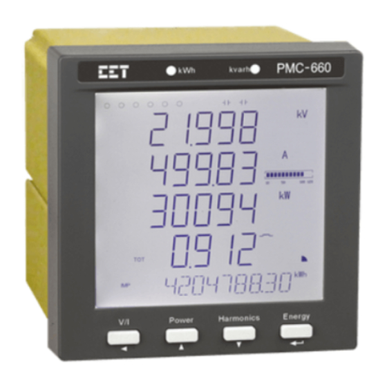
CET Electric Technology Chapter 3 Front Panel The PMC-660 has a large, easy to read LCD display with backlight and four buttons for data display and meter configuration. This chapter introduces the Front Panel operations. Figure 3-1 Front Panel 3.1 Display The Front Panel provides two display modes: Data Display and Setup Configuration. - Page 22 CET Electric Technology A: Measurement symbols for parameters such as Voltage, Current, Fundamental, Power, THD, TOHD, TEHD, 2 to 31 Individual Harmonics, K-Factor, Unbalance, PF, Voltage/Current Phase Angles and Demand, ...etc. B: DI and DO Status Indicators C: Measurement Units, Loading Factor and PF Quadrant status...
-
Page 23: Peak Demand/Max./Min. Display
CET Electric Technology DI Open DI Close DO Open DO Close Units for Voltage, Current, %Harmonic Distortion and Units for Real, Reactive Frequency and Apparent Power C&D Inductive Load COM 1 Port Status %Loading Alarm Symbol Capacitive Load COM 2 Port Status PF Quadrant –... -
Page 24: Using The Front Panel Buttons
CET Electric Technology Area Symbol Description kvar Phase A Phase B Phase C Demand Maximum This Month Last Month Peak Demand/Max./Min. Value Peak Demand/Max./Min. Timestamp (Date Portion) - YYYY.MM.DD Peak Demand/Max./Min. Timestamp (Time Portion) – HH:MM:SS Table 3-2 Peak Demand/Max./Min. Display 3.2 Using the Front Panel Buttons... - Page 25 CET Electric Technology Display Press Button Screens Display 1 Ull average I average kW Total P.F. Total Display 2 Uln average Display 3 Ull average Display 4 I average Display 5 I4 (Measured) I0 (Calculated Display 6 Neutral Current) Display 7~...
- Page 26 CET Electric Technology Display 4 P.F.a P.F.b P.F.c P.F. Total Display 5 dkWa dkWb dkWc dkW Total Display 6 dkvara dkvarb dkvarc dkvar Total Display 7 dkVAa dkVAb dkVAc dkVA Total Display 8 dP.F.a dP.F.b dP.F.c dP.F. Total Display 9...
-
Page 27: Setup Configuration Via The Front Panel
CET Electric Technology Display 13 C (T3) kWh Export Display 14 D (T4) kWh Export Display 15 E (T5) kWh Export Display 16 F (T6) kWh Export Display 17 G (T7) kWh Export Display 18 H (T8) kWh Export Display 19... -
Page 28: Setup Menu
CET Electric Technology 3.4.2 Setup Menu Figure 3-5 Setup Menu... -
Page 29: Front Panel Setup Parameters
CET Electric Technology 3.4.3 Front Panel Setup Parameters The Setup Configuration mode provides access to the following setup parameters: Label Parameters Description Options/Range Default menu PROGRAMMING Programming Setup Configuration mode PASWORD Password Enter Password 0 to 9999 “0” PAS SET... - Page 30 CET Electric Technology Demand Sync. MODE Demand Sync. Mode SLD/SYNC Mode Sliding Window PERIOD Sliding Window Interval 1 to 60 (minutes) Interval Number of Sliding Number of Sliding Windows 1 to 15 Windows Predicted Predicted Demand SENS 70 to 99...
- Page 31 CET Electric Technology Date of the latest firmware UPDAT Update Date e.g. 090821 update Serial Number Meter Serial Number e.g. 0908471895 Table 3-5 Setup Parameters Notes: 1) For 5A configuration, PT Ratio × CT Ratio must be less than 1,000,000.
- Page 32 CET Electric Technology Mode S (Scalar method): 4) There are two ways to calculate the individual harmonic distortion: % of Fundamental Method: Voltage K Harmonic Distortion= is Fundamental Voltage Current K Harmonic Distortion= X100% is Fundamental Current % of RMS Method:...
-
Page 33: Chapter 4 Applications
CET Electric Technology Chapter 4 Applications 4.1 Inputs and Outputs 4.1.1 Digital Inputs The PMC-660 comes standard with six self-excited Digital Inputs that are internally wetted at 24 VDC with a sampling frequency of 1000Hz and programmable debounce. The PMC-660 provides the... -
Page 34: Digital Outputs
CET Electric Technology 4.1.2 Digital Outputs The PMC-660 comes standard with three Form A Electromechanical Digital Outputs. Digital Outputs are normally used for setpoint alarming, load control, or remote control applications. Digital Outputs on the PMC-660 can be used in the following applications: Front Panel Control Manually operated from the Front Panel. -
Page 35: Analog Output
CET Electric Technology mA (for 4-20mA input) and has a range of -999,999 to +999,999. AI Full: This value corresponds to the maximum Analog Input of 20 mA and has a range of - 999,999 to +999,999. For example, to measure the oil temperature of a transformer, connect the outputs of the temperature sensor to the AI terminals of the PMC-660. -
Page 36: Energy Measurements
CET Electric Technology I Sequence* I1 (Positive Sequence) I2 (Negative Sequence) I0 (Zero Sequence) *Available in Firmware V2.00.00 or later Table 4-2 Basic Measurements 4.2.2 Energy Measurements The PMC-660 provides Energy parameters for active energy (kWh), reactive energy (kvarh) and apparent energy (kVAh) with a resolution of 0.01 and a maximum value of ±1,000,000,000.00. -
Page 37: Max./Min. Per Demand Period
CET Electric Technology # of Sliding Number of Sliding Windows. 1* to 15 Windows The Self-Read Time allows the user to specify the time and day of the month for the Peak Demand Self-Read operation. The Self-Read Time supports three options: ... -
Page 38: Power Quality Parameters
CET Electric Technology 240.0° and 120.0°, the Current phase angles should have the values of -60.0°, 180.0° and 60.0°. 4.3.2 Power Quality Parameters The PMC-660 provides the following PQ parameters: 4.3.2.1 Fundamental The PMC-660 provides the following Fundamental Components (Displacement RMS values):... -
Page 39: Unbalance
CET Electric Technology 4.3.3 Unbalance The PMC-660 provides Voltage and Current Unbalance measurements. The calculation method of Voltage and Current Unbalances are listed below: Voltage Unbalance = Current Unbalance = where V1, V2 are the Positive and Negative Sequence Components for Voltage, respectively, and I1, I2 are the Positive and Negative Sequence Components for Current, respectively. -
Page 40: Transients
CET Electric Technology For the Dip/Swell and Interruption detection to work correctly, it’s critically important to set the parameter correctly with the nominal line-to-line voltage on the secondary (meter) side. nominal 4.3.7 Transients The PMC-660 provides Transient Capture capability by detecting sub-cycle voltage disturbances and records the detected event in the PQ Log with timestamp and event type. - Page 41 CET Electric Technology Figure 4-2 Under Setpoint The alarm symbol at the right side of the LCD display is lit if there are any active Setpoints. The setpoints can be programmed over communications and have the following setup parameters: Setup Parameter...
-
Page 42: Logical Module
CET Electric Technology kW Total Present Demand kvar Total Present Demand kvar P.F. Present Demand x1000 Total kW Predicted Demand Total kvar Predicted Demand kvar P.F. Predicted Demand x1000 U THD x100, % U TOHD x100, % U TEHD x100, %... -
Page 43: Logging
CET Electric Technology Specify what action the Logical Module will take when it Trigger 1 becomes active. Logical Equation = ((Source 1 [Mode 1] See Table 4-16 Trigger 2 Source 2) [Mode 2] Source 3) [Mode 3] Source 4 Table 4-14 Setpoint Parameters... -
Page 44: Interval Energy Recorder (Ier) Log
CET Electric Technology complete description of the Self-Read Time and its operation. The Peak Demand of This Month can be reset manually through the Front Panel or via communications. The PMC-660 provides the following Peak Demand parameters: Peak Demand Logs of This Month (Since Last Reset) and Last Month (Before Last Reset) -
Page 45: Pq Log
CET Electric Technology include 16x320, 32x160, 64x80, 128x40 and 256x20. When the WFR format is 256 samples/cycles, the “Pre-fault Cycle” can only be set between 0 and 5. The WFR logs can be retrieved via communications by our PecStar® iEMS or our free PMC Setup Software for display. -
Page 46: Time Of Use (Tou)
CET Electric Technology The DR Log is only operational when the values of Triggered Mode, Recording Mode, Recording Depth, Recording Interval, and Number of Parameters are all non-zero. Data Recorder #X can be triggered by clearing the Data Recorder #X when it is full in Stop-When-Full mode (See Section 5.8.9). -
Page 47: Time Synchronization
CET Electric Technology Each TOU schedule has the following setup parameters and can only be programmed via communications: Setup Parameters Definition Options Specify a daily rate schedule which can be divided into a 1 to 20, the first maximum of 12 periods in 15-min intervals. -
Page 48: On-Board Web Server
CET Electric Technology synchronization interval is 60 minutes. 3) SNTP server can be used to synchronize the PMC-660's clock through its Ethernet port providing that the network where the PMC-660 resides has access to the Internet. The programming of the SNTP server is only supported over communications. -
Page 49: Meter Email
CET Electric Technology Figure 4-5 PMC-660's Web Page 4.10 Meter Email The PMC-660 supports the SMTP and ESMTP protocols and can be configured to send alarm messages via email, which may be triggered by Setpoint, Dip/Swell and Transient Detection. The email shows the following information in text format: PMC-660’s serial number... - Page 50 CET Electric Technology Figure 4-6 Topological Graph To use the PMC-660 as an Ethernet Gateway, the following parameters should be configured via the Front Panel: Set the IP address, Subnet Mask and Gateway Address Set the Protocol of the RS485 Port as EGATE Use 6000 (cannot be configured) as the IP Port No.
-
Page 51: Chapter 5 Modbus Register Map
CET Electric Technology Chapter 5 Modbus Register Map This chapter provides a complete description of the Modbus register map (Protocol Version 1.6) for the PMC-660 to facilitate the development of 3 party communications driver for accessing information on the PMC-660. For a complete Modbus Protocol Specification, please visit http://www.modbus.org. The... - Page 52 CET Electric Technology 0076 Uan (Wye)/Uab (Delta/3P3W) Angle UINT16 0077 Ubn (Wye)/Ubc (Delta/3P3W) Angle UINT16 x100 ° 0078 Ucn (Wye)/Uca (Delta/3P3W) Angle UINT16 0079 Ia Angle UINT16 0080 Ib Angle UINT16 x100 ° 0081 Ic Angle UINT16 0082 Float 0084...
-
Page 53: Energy Measurements
CET Electric Technology The range of the SOE/PQ/WFR/IER/DR Log Pointer is between 0 and 0xFFFFFFFFH. The pointer is incremented for every new log generated and will roll over to 0 if its current value is 0xFFFFFFFFH. A value of zero indicates that the specific Log does not contain any record. - Page 54 CET Electric Technology 4010 kWh Import of T2 UINT32 4012 kWh Export of T2 UINT32 4014 kvarh Import of T2 UINT32 kvarh 4016 kvarh Export of T2 UINT32 4018 kVAh of T2 UINT32 kVAh 4020 kWh Import of T3 UINT32...
-
Page 55: Interval Energy Measurements
CET Electric Technology 4158 kVAh of T6 Float VA.s 4160 kWh Import of T7 Float 4162 kWh Export of T7 Float 4164 kvarh Import of T7 Float var.s 4166 kvarh Export of T7 Float 4168 kVAh of T7 Float VA.s... -
Page 56: Harmonic Measurements
CET Electric Technology 0446 dkVAc Float 0448 dkVA Total Float 0450 dP.F.a Float 0452 dP.F.b Float 0454 dP.F.c Float 0456 dP.F. Total Float Table 5-7 Fundamental Measurements Notes: When the Wiring Mode is Delta or 3P3W, the fundamental components of per phase line-to-neutral Voltages, kWs, kvars, kVAs and P.F.s have no meaning, and their registers are reserved. -
Page 57: High-Speed Measurements
CET Electric Technology Otherwise, they are reserved. 5.5 High-speed Measurements Register Property Description Format Scale Unit 0930 Float 0932 Float 0934 Float 0936 Uln average Float 0938 Float 0940 Float 0942 Float 0944 Ull average Float 0946 Float 0948 Float... -
Page 58: Predicted Demand
CET Electric Technology 1034 kvara INT32 1036 kvarb INT32 1038 kvarc INT32 1040 kvar Total INT32 1042 kVAa INT32 1044 kVAb INT32 1046 kVAc INT32 1048 kVA Total INT32 1050 P.F.a INT32 1052 P.F.b INT32 x1000 1054 P.F.c INT32 1056 P.F. -
Page 59: Max./Min. Per Demand Period
CET Electric Technology 1272 Ib THD INT32 1274 Ic THD INT32 Table 5-11 Predicted Demand Notes: I4 Predicted Demand is valid only if the device is equipped with the I4 option, and it will be automatically changed to I0 (Zero Sequence Current) Predicted Demand if the meter is equipped with the AI option. -
Page 60: Peak Demand Log Of This Month (Since Last Reset)
CET Electric Technology 1634 kvara Min. INT32 1636 kvarb Min. INT32 1638 kvarc Min. INT32 1640 kvar Total Min. INT32 1642 kVAa Min. INT32 1644 kVAb Min. INT32 1646 kVAc Min. INT32 1648 kVA Total Min. INT32 1650 P.F.a Min. - Page 61 CET Electric Technology 5.7.1.1 Max. Log of This Month (Since Last Reset) Register Property Description Format Scale Unit 2000~2005 2006~2011 2012~2017 2018~2023 Uln average x100 2024~2029 2030~2035 2036~2041 2042~2047 Ull average 2048~2053 2054~2059 x1000 2060~2065 2066~2071 I average 2072~2077 2078~2083...
- Page 62 CET Electric Technology 2444~2449 Ia K-Factor 2450~2455 Ib K-Factor 2456~2461 Ic K-Factor 2462~2467 U Unbalance 2468~2473 I Unbalance 2474~2479 I Residual x1000 Table 5-17 Min. Log of This Month (Since Last Reset) Notes: I4 is valid only if the device is equipped with the I4 option, and it will be automatically changed to I0 (Zero Sequence Current) if the meter is equipped with the AI option.
-
Page 63: Soe Log
CET Electric Technology 2978~2983 kW Total 2984~2989 kvar Total 2990~2995 kVA Total 2996~3001 P.F. Total x1000 3002~3007 FREQ x100 3008~3013 Uan (WYE)/Uab (Delta/3P3W) THD 3014~3019 Ubn (WYE)/Ubc (Delta/3P3W) THD 3020~3025 Ucn (WYE)/Uca (Delta/3P3W) THD x100 3026~3031 Ia THD 3032~3037 Ib THD... -
Page 64: Log Data Format
CET Electric Technology High-order Byte: Year 0-99 (Year-2000) UINT16 Low-order Byte: Month 1 to 12 High-order Byte: Day 1 to 31 UINT16 Low-order Byte: Hour 0 to 23 High-order Byte: Minute 0 to 59 UINT16 Low-order Byte: Second 0 to 59... -
Page 65: Pq Log Data Structure
CET Electric Technology Note: Please refer to Section 5.8.1 Read General Reference Packet Structure for how to retrieve the energy log. 5.8.3 PQ Log Data Structure Offset Property Description Format 0 to 7 PQ Log 1 8 to 15 PQ Log 2... -
Page 66: Data Recorder Log Data Structure
CET Electric Technology Where Uln = (Ull ÷√3) nominal nominal When the Wiring Mode is 3P3W or Delta: Event Value 1: Maximum %Residual Ull, x100 Event Value 2: Duration (us) Event Value 3: %Residual Uab /Ull , x100 nominal Event Value 4: %Residual Ubc... -
Page 67: Device Setup
CET Electric Technology 5.9 Device Setup 5.9.1 Basic Setup Register Property Description Format Range Default 5999 PT Ratio-Fraction UINT16 0 to 9999 6000 PT Ratio-Integer UINT16 1 to 10000 1 to 6,000 (5A input) 6001 CT Ratio UINT16 1 to 30,000 (1A input) - Page 68 CET Electric Technology 6=kvarh Total 6052 DO1 Pulse Width UINT16 0 to 999 (x0.1s) 6053 DO2 Pulse Width UINT16 0=Latch Mode 6054 DO3 Pulse Width UINT16 6055 AI Type UINT16 0=4-20mA, 1=0-20mA 6056 AI Zero scale INT32 -999,999 to +999,999...
- Page 69 CET Electric Technology For 5A configuration, PT Ratio × CT Ratio must be less than 1,000,000 The last Octet of the IP Address, Subnet Mask and Gateway can neither be “0000 0000” nor “1111 1111”. If the IP Address is “192.168.8.97”, write “0xC0A80861” to this register. The default values for the IP Address, Subnet Mask and Gateway Address are 192.168.0.100, 255.255.255.0 and 192.168.0.1, respectively.
-
Page 70: Setpoint Setup
CET Electric Technology GMT-8:00 GMT+5:30 GMT-7:00 GMT+5:45 GMT-6:00 GMT+6:00 GMT-5:00 GMT+6:30 GMT-4:00 GMT+7:00 GMT-3:30 GMT+8:00 GMT-3:00 GMT+9:00 GMT-2:00 GMT+9:30 GMT-1:00 GMT+10:00 GMT-0:00 GMT+11:00 GMT+1:00 GMT+12:00 GMT+2:00 GMT+13:00 GMT+3:00 Table 5-34 Time Zones The SNTP Sync. Interval should be set between 10 and 1440 minutes. - Page 71 CET Electric Technology Setpoint 1=Over Setpoint 2=Under Setpoint Paramenter UINT16 1 to 34 Active Limit INT32 999,999 Inactive Limit INT32 999,999 Active Delay UINT16 0 to 9999 s Inactive Delay UINT16 0 to 9999 s Trigger 1 UINT16 0 to 22...
- Page 72 CET Electric Technology DR #1 DR #13 DR #2 DR #14 DR #3 DR #15 DR #4 DR #16 DR #5 WFR #1 DR #6 WFR #2 DR #7 Alarm Email DR #8 Table 5-38 Setpoint Triggers 5.9.3 Logical Module Setup 5.9.3.1 Logical Module Setup Registers...
-
Page 73: Data Recorder Setup
CET Electric Technology 5.9.4 Data Recorder Setup 5.9.4.1 Data Recorder Setup Registers Register Property Description Format 7000~7022 Data Recorder #1 (High-Speed) See Section 5.9.4.2 7023~7045 Data Recorder #2 (High-Speed) High-speed Data Recorder 7046~7068 Data Recorder #3 (High-Speed) Setup Data Structure... -
Page 74: Interval Energy Recorder Setup Registers
CET Electric Technology For High Speed Data Recorder, the Recording Mode only supports Stop-When-Full. If Recording Depth is set to “0”, the Data Recorder will be disabled. Recording Offset should be set to zero for High-Speed Data Recorder. Appendix A provides a list of available parameters for data recording. Parameters 0 to 28 are available for high-speed data recording. -
Page 75: Waveform Recorder (Wfr) Setup
CET Electric Technology Low-order Byte: 1 to 12 Month High-order Byte: 1 to 31 7704 UINT16 Low-order Byte: 0 to 23 Hour High-order Byte: 0 to 59 Minute 7705 UINT16 Low-order Byte: 0 to 59 Second 7706 Number of Parameters... - Page 76 CET Electric Technology 0 to 11 16002 Current Period UINT16 (Period #1 to #12) 0 to 19 16003 Current Daily Profile No. UINT16 (Daily Profile #1 to #20) 0=Weekday1 1=Weekday2 16004 Current Day Type UINT16 2=Weekday3 3= Alternate Day 16005 Current TOU No.
- Page 77 CET Electric Technology Season #7: Weekday#1 Daily Profile UINT16 Season #7: Weekday#2 Daily Profile UINT16 0 to 19 Season #7: Weekday#3 Daily Profile UINT16 Season #8: Start Date UINT16 See Season #2: Start Date Season #8: Weekday#1 Daily Profile UINT16...
- Page 78 CET Electric Technology 17368~17391 Daily Profile #8 17392~17415 Daily Profile #9 17416~17439 Daily Profile #10 17440~17463 Daily Profile #11 17464~17487 Daily Profile #12 17488~17511 Daily Profile #13 17512~17535 Daily Profile #14 17536~17559 Daily Profile #15 17560~17583 Daily Profile #16 17584~17607...
-
Page 79: Do Control
CET Electric Technology Alternate Day #2 Date¹ UINT32 Table 5-55 Alternate Day #2 Daily Profile UINT16 0 to 19 Alternate Day #3 Date¹ UINT32 Table 5-55 Alternate Day #3 Daily Profile UINT16 0 to 19 Alternate Day #4 Date¹ UINT32... -
Page 80: Clear/Reset Control
CET Electric Technology a particular DO operation. The DO will be “Disarmed” automatically if an “Execute” command is not received within 15 seconds after it has been “Armed”. If an “Execute” command is received without first having received an “Arm” command, the meter ignores the “Execute” command and returns the 0x04 exception code. -
Page 81: Time
CET Electric Technology 5.10 Time There are two sets of Time registers supported by the PMC-660 – Year / Month / Day / Hour / Minute / Second (Registers # 60000 to 60002) and UNIX Time (Register # 60004). When sending time to the PMC- 660 over Modbus communications, care should be taken to only write one of the two Time register sets. - Page 82 CET Electric Technology B5B4: 00: 5A I4 CT 01: 1A I4 CT 10: Analog Input 11: Reserved Other bits are reserved. 0=5 (A) 3-Phase CT 60230 9830 Current configuration UINT16 1=1 (A) 3-Phase CT 0=120 (V) , 1=415 (V)
-
Page 83: Appendix A - Data Recorder Parameter
CET Electric Technology Appendix A - Data Recorder Parameter Parameters Scale/Unit Parameters Scale/Unit x100, V x100, V x100, V Uln average x100, V x100, V x100, V x100, V Ull average x100, V x1000, A x1000, A x1000, A I average... - Page 84 CET Electric Technology Ia 11 Harmonic x100, % Ib 11 Harmonic x100, % Ic 11 Harmonic x100, % Ia 12 Harmonic x100, % Ib 12 Harmonic x100, % Ic 12 Harmonic x100, % Ia 13 Harmonic x100, % Ib 13...
- Page 85 CET Electric Technology Uln avg. min Uab min x100, V x100, V Per Demand Period per Demand Period Ubc min Uca min x100, V x100, V per Demand Period per Demand Period Ull avg. min Ia min x100, V x1000, A...
-
Page 86: Appendix B - Data Recorder Default Settings
CET Electric Technology Appendix B - Data Recorder Default Settings Parameter DR 1 (HS) DR 2 (HS) DR 3 (HS) DR 4 (HS) Trigger Mode Disabled Disabled Disabled Disabled Recording Mode Stop-When-Full Stop-When-Full Stop-When-Full Stop-When-Full Recording Depth Recording Interval Recording Offset... - Page 87 CET Electric Technology Ubn max per Demand Ubn THD max per Ubc min per Demand Ubn min per Demand Parameter 2 Period Demand Period Period Period Ucn max per Demand Ucn THD max per Uca min per Demand Ucn min per Demand...
-
Page 88: Appendix C - Soe Event Classification
CET Electric Technology Appendix C – SOE Event Classification Event Sub- Event Value Description Classification Classification Scale/Option 1 / 0 DI1 Close/DI1 Open 1 / 0 DI2 Close/DI2 Open 1 / 0 DI3 Close/DI3 Open 1 / 0 DI4 Close/DI4 Open... - Page 89 CET Electric Technology Return Value (x100) Over Current TEHD Setpoint Return Return Value (x10) Over Voltage Unbalance Setpoint Return Return Value (x10) Over Current Unbalance Setpoint Return Return Value (x100) Over Voltage Deviation Setpoint Return Over Phase Reversal e Setpoint Return...
- Page 90 CET Electric Technology Setpoint Parameter Fault Data Recorder Parameter Fault Waveform Recorder Parameter Fault Energy Log Parameter Fault TOU Parameter Fault Power On Power Off Set Clock via Front Panel Setup Changes via Front Panel Clear DI Counter via Front Panel...
-
Page 91: Appendix D - Technical Specifications
CET Electric Technology Appendix D - Technical Specifications Voltage Inputs (V1, V2, V3, VN) Standard (Un) 240VLN/415VLL Optional (Un) 69VLN/120VLL, 400VLN/690VLL Range 10% to 120% Un PT Ratio 1-10,000 Overload 1.2xUn continuous, 2xUn for 10s Burden <0.5VA @ 240V Frequency... - Page 92 CET Electric Technology Accuracy Parameters Accuracy Resolution Voltage ±0.1% 0.001V Current ±0.1% 0.001A I4 Measured ±0.1% 0.001A Ir Calculated ±0.1% F.S. 0.001A kW, kvar, kVA ±0.2% 0.001k kWh, kVAh IEC 62053-22 Class 0.2S 0.01kXh kvarh IEC 62053-24 Class 0.5S 0.01kvarh P.F.
-
Page 93: Appendix E - Standards Compliance
CET Electric Technology Appendix E - Standards Compliance Safety Requirements LVD Directive 2014 / 35 / EU EN61010-1: 2010 EN61010-2-030: 2010 Electrical safety in low voltage distribution systems up to 1000Vac IEC 61557-12: 2008 (PMD) and 1500 Vdc Insulation IEC 62052-11: 2003 AC Voltage: 4kV @ 1 minute Insulation resistance: >100MΩ... -
Page 94: Appendix F - Ordering Guide
CET Electric Technology Appendix F – Ordering Guide... - Page 95 CET Electric Technology CET Inc. 8/F, Westside, Building 201, Terra Industrial & Tradepark, Che Gong Miao, Shenzhen, Guangdong, P.R.China 518040 Tel: +86.755.8341.5187 Fax: +86.755.8341.0291 sales@cet-global.com www.cet-global.com...
Need help?
Do you have a question about the PMC-660 Series and is the answer not in the manual?
Questions and answers