Table of Contents
Advertisement
Quick Links
Advertisement
Table of Contents

Related Manuals for CET PMC-352


Summary of Contents for CET PMC-352
- Page 1 PMC-352 3-Phase LoRa DIN Energy Meter User Manual Version: V1.0A July 27, 2020...
- Page 2 The information contained in this manual is believed to be accurate at the time of publication; however, CET assumes no responsibility for any errors which may appear here and reserves the right to make changes without notice. Please consult CET or your local representative for the latest product specifications.
- Page 3 DANGER Failure to observe the following instructions may result in severe injury or death and/or equipment damage. Installation, operation and maintenance of the meter should only be performed by qualified, competent personnel that have the appropriate training and experience with high voltage and current devices.
- Page 4 CET does not accept liability for any damage caused by meter malfunctions. CET accepts no responsibility for the suitability of the meter to the application for which it was purchased.
-
Page 5: Table Of Contents
Chapter 1 Introduction ........................... 1 1.1 Overview ........................... 1 1.2 Features ............................ 1 1.3 PMC-352’s application in a wireless IoT based EMS using LoRa network ......... 2 1.4 Getting more information ......................2 Chapter 2 Installation..........................3 2.1 Appearance ..........................3 2.1.1 Main Unit ........................ - Page 6 CET Electric Technology 4.5.1 Power Quality Measurements ..................22 4.5.2 Current Harmonic Measurements ................23 4.5.3 Voltage Harmonic Measurements ................23 4.6 Present Demands ........................23 4.7 SOE Log ........................... 23 4.8 Device Setup ........................... 26 4.8.1 Basic Setup ........................26 4.8.2 I/O Setup ........................
-
Page 7: Chapter 1 Introduction
CET Electric Technology Chapter 1 Introduction This manual explains how to use the PMC-352 3-Phase LoRa DIN Energy Meter. Throughout the manual the term “meter” generally refers to all models. This chapter provides an overview of the PMC-352 meter and summarizes many of its key features. -
Page 8: Pmc-352'S Application In A Wireless Iot Based Ems Using Lora Network
1.3 PMC-352’s application in a wireless IoT based EMS using LoRa network The PMC-352 can be used to monitor 3-phase or single-phase power system and become a vital component of an intelligent, distributed and wireless loT based EMS or Condition Monitoring System. -
Page 9: Chapter 2 Installation
Chapter 2 Installation Caution Installation of the PMC-352 should only be performed by qualified, competent personnel who have the appropriate training and experience with high voltage and current devices. The meter must be installed in accordance with all local and national electrical codes. -
Page 10: Split-Core Ct Appearances & Specifications
CET Electric Technology 2.1.3 Split-Core CT Appearances & Specifications Figure 2-2 Split-Core CT Appearances & Specifications 2.1.4 Antenna Appearances & Specifications Figure 2-3 Antenna Appearances & Specifications 2.1.5 Connecting Cable (For 800A/40mA and 1600A/40mA SCCT only) Figure 2-4 Connecting Cable... -
Page 11: Dimensions
CET Electric Technology 2.2 Dimensions 2.2.1 Unit Dimensions Figure 2-5 Unit Dimensions 2.2.2 Terminal Dimensions Figure 2-6 Terminal Dimensions... -
Page 12: Ct Dimensions
CET Electric Technology 2.3 CT Dimensions 2.3.1.1 5A/2mA, 100A/40mA, 200A/40mA or 400A/40mA SCCT Model PMC-SCCT-5A-2mA-16-A 19.9 28.6 30.26 Ø16.1 48.9 30.7 33.9 PMC-SCCT-100A-40mA-16-A 19.9 28.6 30.26 Ø16.1 48.9 30.7 33.9 PMC-SCCT-200A-40mA-24-A 40.5 53.5 44.3 Ø24.1 70.0 45.0 40.2 PMC-SCCT-400A-40mA-35-A 22.5 57.3... -
Page 13: Ntc Dimensions
Figure 2-8 1600A SCCT Dimension 2.3.2 NTC Dimensions 2.3.2.1 NTC-104/NTC-1043/NTC-1044 Figure 2-9 NTC-104/NTC-1043/NTC-1044 Dimensions 2.3.2.2 NTC-103M4/NTC-103M10/NTC-104M10 Figure 2-10 NTC-103M4/NTC-103M10/NTC-104M10 Dimensions 2.4 Mounting The PMC-352 should be installed in a dry environment with no dust and kept away from heat, radiation and electrical noise source. -
Page 14: Wiring Mode
352 downward to the “unlock” position. 3. Align the top of the mounting channel at the back of the PMC-352 at an angle against the top of the DIN rail as shown in Figure 2-11 right. 4. Rotate the bottom of the PMC-352 towards the... - Page 15 CET Electric Technology 3P3W Direct Connection with 2CTs 3P3W Direct Connection with 2PTs, 2CTs 1P3W with 2CTs 1P2W Uln with 1CT 1P2W Ull with 1CT 3x1P with 3CTs Figure 2-12 Wiring Modes...
-
Page 16: Scct Installation
These SCCTs come with a pluggable connector at the end of the output wires. Insert the 2-pin pluggable connector securely into the Current Input terminal on the PMC-352. b. Open the SCCT by slightly pulling on the clip. Please ensure that SCCT’s contact surface is clean and without contaminants for best accuracy performance. -
Page 17: Lora Antenna Installation
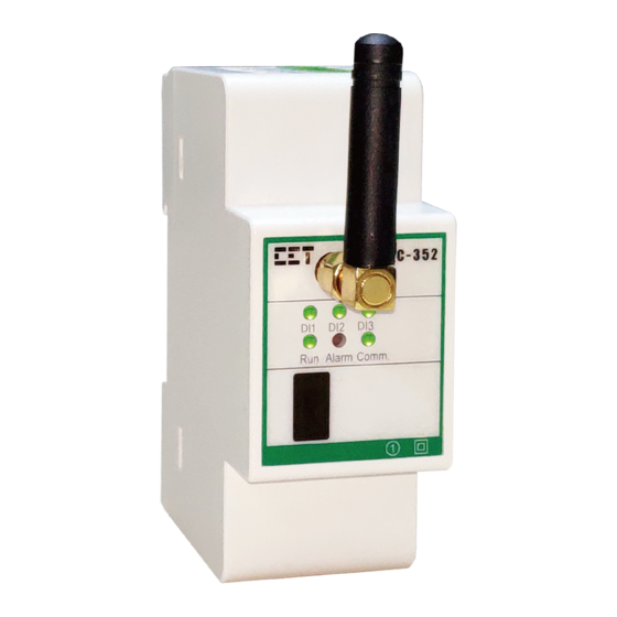
2. Please ensure the Load Current does not exceed the CT’s Primary Current specification. 2.7 LoRa Antenna Installation Connect either the 4dBi or 2.5dBi antenna to the PMC-352 by applying the correct torque to tighten the connection as shown in the figure below. For best communication performance, the antenna should be mounted outside of a metal enclosure and preferably positioned vertically. -
Page 18: Ntc Input Wiring
V1 and V3 terminals. As a result, the self-powered option should only be used in a 3-phase power system. If the PMC-352 is used in a single-phase power system, the independent power supply option should be used instead. -
Page 19: Chapter 3 Applications
Chapter 3 Applications 3.1 Inputs 3.1.1 Digital Inputs The PMC-352 comes standard with three self-excited Digital Inputs that are internally wetted at 24VDC. Digital Inputs on the PMC-352 can be used in the following applications: Digital Input The digital inputs are typically used for status monitoring which can help prevent equipment damage, improve maintenance, and track security breaches. -
Page 20: Demand Measurements
Demand is defined as the average power consumption over a fixed interval (usually 15 minutes) based on the Sliding Window method. The PMC-352 provides Present Demand for Ia, Ib, Ic, kW Total, kvar Total and kVA Total, updated once a second. Only Import Demand is provided for kW Total, kvar total and kVA Total. -
Page 21: Setpoints
3.4 Setpoints The PMC-352 comes standard with 10 user-programmable Setpoints which provide extensive control by allowing a user to initiate an action in response to a specific condition. Typical setpoint applications include alarming, fault detection and power quality monitoring. - Page 22 Table 3-7 Setpoint Parameters Notes: For the PMC-352, the Trigger registers are reserved and the Alarm indicator on the Front Panel would be lit when any Setpoint becomes active. The Setpoint status is stored in the register 0100. When Phase Reversal is set as the Setpoint Parameter, the Setpoint Type should be set to 1 (i.e., Over Setpoint). The Setpoint Type=2 (i.e., Under Setpoint) is invalid.
-
Page 23: Soe Log
CET Electric Technology 3.5 SOE Log The PMC-352’s SOE Log can store up to 16 events such as Power-on, Power-off, Digital Input status changes, Setup changes and Setpoint events in its non-volatile memory. Each event record includes the event classification, its relevant parameter values and a timestamp in ±1 ms resolution. The SOE Log can be retrieved or reset via communications. -
Page 24: Current Phase Loss
CET Electric Technology where Un and Iprim represent the Voltage and Current nominal in Primary values. For the Voltage and Current Phase Loss detection to work correctly, the PT Primary and CT Primary should be configured to represent the respective nominal values. -
Page 25: Chapter 4 Modbus Register Map
This chapter provides a complete description of the Modbus register map (Protocol Version 1.0) for the PMC-352 to facilitate the development of 3 party communications driver for accessing information on the PMC-352. For a complete Modbus Protocol Specification, please visit http://www.modbus.org. The PMC-352 supports the following Modbus functions: Read Holding Registers (Function Code 0x03) -
Page 26: Energy Measurements
CET Electric Technology 0088 Float 0090 Float 0092 Float 0094~0095 Reserved UINT16 0096 DI Status UINT16 0097 Voltage Phase Active Status UINT16 0098 Temp. Self-diagnostic Status UINT16 0099 Reserved UINT16 0100 Setpoint Alarm Status UINT16 0101 Wiring Diagnostic Status UINT16... -
Page 27: 3-Phase Energy Measurements
CET Electric Technology 4.2.1 3-Phase Energy Measurements Register Property Description Format Scale Unit 0500 kWh Import INT32 0502 kWh Export INT32 0504 kWh Net INT32 0506 kWh Total INT32 0508 kvarh Import INT32 0510 kvarh Export INT32 kvarh 0512 kvarh Net INT32 x0.01... -
Page 28: Di Pulse Counter
CET Electric Technology 0880 kvarh Q2 INT32 0882 kvarh Q3 INT32 0884 kvarh Q4 INT32 Table 4-7 Phase C Energy Measurements 4.3 DI Pulse Counter Register Property Description Format Range/Unit 1200 DI1 Pulse Counter UINT32 0 to 999,999,999 1202 DI2 Pulse Counter... -
Page 29: Current Harmonic Measurements
CET Electric Technology 1332 Current Unbalance Float Table 4-10 Power Quality Measurements 4.5.2 Current Harmonic Measurements Register Property Description Format Scale Unit 1400 Ia THD Float 1402 Ib THD Float 1404 Ic THD Float 1406 Ia TOHD Float 1408 Ib TOHD... - Page 30 CET Electric Technology Register Property Description Format 10000~10007 Event 1 10008~10015 Event 2 10016~10023 Event 3 10024~10031 Event 4 10032~10039 Event 5 10040~10047 Event 6 10048~10055 Event 7 10056~10063 Event 8 See Note 1) 10064~10071 Event 9 10072~10079 Event 10...
- Page 31 CET Electric Technology Over TC2 Setpoint Active/Return Over TC3 Setpoint Active/Return Over TC4 Setpoint Active/Return Over Ia Setpoint Active/Return Over Ib Setpoint Active/Return Over Ic Setpoint Active/Return Over Uan Setpoint Active/Return Over Ubn Setpoint Active/Return Over Ucn Setpoint Active/Return 38~40...
-
Page 32: Device Setup
800A or 1600A SCCT. The CT Primary and CT Secondary setup registers are disregarded in this case. The wiring modes of 1P2W_LN, 1P2W_LL, 1P3W and 3X1P are only supported when the PMC-352 is ordered with independent power supply option (please refer to Appendix C Ordering Guide for more information). The self-powered supply option derives the power from the V1 and V3 inputs of a 3-phase power system. -
Page 33: Comm. Setup
If Baud Rate is set to an invalid value, it will default to 9600bps automatically. If LoRa Gateway is enabled, the PMC-352 would act as a LoRa Master and transfer any RS-485 packets that are received from the Modbus Master on its RS-485 port but not destined for itself, via LoRa to downstream PMC-352s that operate on the same LoRa Channel and vice versa. -
Page 34: User-Defined Data Map
100% Table 4-22 Setpoint Parameters For the PMC-352, the Trigger registers are reserved and the Alarm indicator on the Front Panel would be lit when any Setpoint becomes active. The Setpoint status is stored in the register 0100. When Phase Reversal is set as the Setpoint Parameter, the Setpoint Type should be set to 1 (i.e., Over Setpoint). The Setpoint Type=2 (i.e., Under Setpoint) is invalid. -
Page 35: Time
Table 4-24 User-defined Parameters List 4.9 Time There are two sets of Time registers supported by the PMC-352 – Year/Month/Day/Hour/Minute/ Second (Register # 60000 to 60002) and UNIX Time (Register # 60004). When sending time to the PMC- 352 over Modbus communications, care should be taken to only write one of the two Time register sets. -
Page 36: Clear/Reset Control
Feature Code UINT16 See Note 2 Table 4-27 Meter Information Notes: 1. The Meter Model appears in registers 60200 to 60219 and contains the ASCII encoding of the string “PMC-352-C” as shown in the following table. Register Value(Hex) ASCII 60200... - Page 37 60208 0x0043 60209-60219 0x0020 Null Table 4-28 ASCII Encoding of “PMC-352-C” 2. The following table illustrates the details for the Feature Code register. B6 to B15 B3 to B5 (Expansion Communication) B0 to B2 (Input Current) 0= N (None), 2=7 (LoRa)
-
Page 38: Appendix A Technical Specifications
CET Electric Technology Appendix A Technical Specifications Voltage Inputs (V1, V2, V3, VN) Voltage (Un) 277VLN/480VLL Range 40V to 1.2Un (88V to 550V for Self-Powered option) Burden <0.02VA/phase Frequency 45-65Hz Current Inputs (I11, I12, I21, I22, I31, I32) SCCT Option... -
Page 39: Appendix B Standards Of Compliance
CET Electric Technology Appendix B Standards of Compliance Safety Requirements CE LVD 2014 / 35 / EU EN 61010-1: 2010 EN 61010-2-030: 2010 Electrical Safety in Low Voltage Distribution IEC 61557-12: 2018 (PMD) Systems up to 1000VAC and 1500VDC Insulation... -
Page 40: Appendix C Ordering Guide
CET Electric Technology Appendix C Ordering Guide... - Page 41 CET Electric Technology Accessories Ordering Guide Split-Core CTs NTC Thermistors...
-
Page 42: Contact Us
CET Electric Technology Contact us CET Electric Technology Inc. Email: support@cet-global.com Web: www.cet-global.com...
Need help?
Do you have a question about the PMC-352 and is the answer not in the manual?
Questions and answers