Table of Contents
Advertisement
Quick Links
Advertisement
Table of Contents

Related Manuals for CET PMC-D721MD


Summary of Contents for CET PMC-D721MD
- Page 1 PMC-D721MD Digital Multifunction Meter User Manual Version: V1.0 June 25, 2018...
- Page 2 The information contained in this manual is believed to be accurate at the time of publication; however, CET assumes no responsibility for any errors which may appear here and reserves the right to make changes without notice. Please consult CET or your local representative for the latest product specifications.
- Page 3 CET Electric Technology DANGER Failure to observe the following instructions may result in severe injury or death and/or equipment damage. Installation, operation and maintenance of the meter should only be performed by qualified, competent personnel that have the appropriate training and experience with high voltage and current devices.
- Page 4 Limited warranty CET offers the customer a minimum of 12-month functional warranty on the meter for faulty parts or workmanship from the date of dispatch from the distributor. This warranty is on a return to factory for repair basis.
-
Page 5: Table Of Contents
CET Electric Technology Table of Contents Chapter 1 Introduction ..........................7 1.1 Overview ............................ 7 1.2 Features ............................7 1.3 Getting more information ......................8 Chapter 2 Installation ..........................9 2.1 Appearance ..........................9 2.2 Unit Dimensions ........................10 2.3 Mounting ..........................10 2.4 Input Wiring .......................... - Page 6 CET Electric Technology Appendix B Standards Compliance ......................25 Appendix C Ordering Guide ........................26 Contact us ............................... 27...
-
Page 7: Chapter 1 Introduction
This manual explains how to use the PMC-D721MD DC Multifunction Meter. Throughout the manual the term “meter” generally refers to all models. Differences between the models are indicated with the appropriate model number. This chapter provides an overview of the PMC-D721MD meter and summarizes many of its key features. 1.1 Overview The PMC-D721MD DC Multifunction Meter is CET’s latest offer for the low-cost DC metering market. -
Page 8: Getting More Information
Supported by CET’s PecStar® iEMS and PMC Setup Easy integration into other Automation, SCADA or BMS systems via Modbus RTU 1.3 Getting more information Additional information is available from CET via the following sources: Visit www.cet-global.com ... -
Page 9: Chapter 2 Installation
Chapter 2 Installation Caution Installation of the PMC-D721MD should only be performed by qualified, competent personnel that have the appropriate training and experience with high voltage and current devices. The meter must be installed in accordance with all local and national electrical codes. -
Page 10: Unit Dimensions
CET Electric Technology 2.2 Unit Dimensions Figure 2-3 Dimension 2.3 Mounting The PMC-D721MD meter should be installed in a dry environment with no dust and kept away from heat, radiation and electrical noise source. Installation steps: Remove the installation clips from the meter ... -
Page 11: Input Wiring
The following figure illustrates the RS485 communications connections on the PMC-D721MD: Figure 2-6 Communications Connections The PMC-D721MD provides one RS485 port and supports the Modbus RTU protocol. Up to 32 devices can be connected on a RS485 bus. The overall length of the RS485 cable connecting all devices should not exceed 1200m. -
Page 12: Pulse Output Wiring
CET Electric Technology 2.7 Pulse Output Wiring The following figure illustrates the Pulse Output connections on the PMC-D721MD: Figure 2-8 Pulse Output Connections 2.8 Power Supply Wiring For AC supply, connect the live wire to the L/+ terminal and the neutral wire to the N/- terminal. -
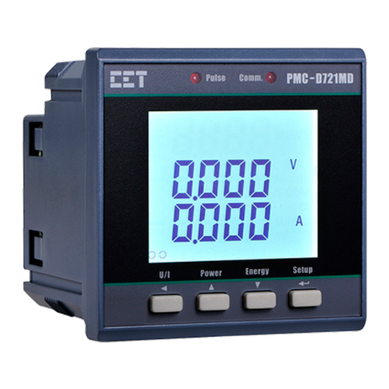
Page 13: Chapter 3 Front Panel
CET Electric Technology Chapter 3 Front Panel The PMC-D721MD meter has a large, bright, backlit LCD display and four buttons for data display and meter configuration. This chapter introduces the front panel operations. Figure 3-1 Front Panel 3.1 Display 3.1.1 LCD Testing Pressing both the <Phase>... - Page 14 CET Electric Technology D: DI Status and kWh Imp/Exp indicators. DO Status and kWh Net/Total indicators are reserved. Figure 3-3 LCD Display The following table shows the special LCD display symbols: Label Description Voltage Current Reserved Measurement Units of Power (kW) and Energy (kWh).
-
Page 15: Using The Front Panel Buttons
Table 3-2 Buttons Description 3.3 LED Pulse Outputs The PMC-D721MD comes standard with one LED indicator for Energy Pulse Output which can be used for kWh energy pulsing if the EN PULSE is enabled (see Section 4.2 LED Pulse Outputs for more information) and a second LED indicator for Communication Status. -
Page 16: Making Setup Changes
CET Electric Technology 3.5.1 Making Setup Changes Entering the Password: Press the <Setup> button for more than 2 seconds to access Setup Configuration mode. Press the <Energy> button to advance to the Password page. A correct password must be entered before changes are allowed. The factory default password is zero. -
Page 17: Configuration
Version V1.00.00 PROT VER Protocol Version Protocol Version e.g. 1.0 means V1.0 UPDT Update Date Firmware Update Date e.g. 20130603 Table 3-4 Setup Parameters Notes: The I/O setup parameters are only displayed when the PMC-D721MD is equipped with this option. -
Page 18: Chapter 4 Applications
Digital Input status are stored as events in the SOE Log in 1 ms resolution. 4.2 Pulse Outputs The PMC-D721MD comes standard with one front panel LED Pulse Output for Energy Pulsing and can be equipped with two optional Solid Relay Output for kWh Imp and kWh Exp energy pulsing where DO Energy Pulse Outputs are typically used for accuracy testing. -
Page 19: Chapter 5 Modbus Register Map
Chapter 5 Modbus Register Map This chapter provides a complete description of the Modbus register map (Protocol Versions 1.0 and above) for the PMC-D721MD Digital Multifunction Meter to facilitate the development of 3 party communications driver for accessing information on the PMC-D721MD. - Page 20 CET Electric Technology 10016~10023 Event 3 Data Structure 10024~10031 Event 4 10032~10039 Event 5 10040~10047 Event 6 10048~10055 Event 7 10056~10063 Event 8 10064~10071 Event 9 10072~10079 Event 10 10080~10087 Event 11 10088~10095 Event 12 … … 10248~10255 Event 32...
-
Page 21: Device Setup
Table 5-8 Communication Setup 5.4 Time There are two sets of Time registers supported by the PMC-D721MD – Year / Month / Day / Hour / Minute / Second (Register # 60000 to 60002) and UNIX Time (Register # 60004). When sending time to the PMC-D721MD over Modbus communications, care should be taken to only write one of the two Time register sets. -
Page 22: Clear Control
B2B1B0: 000: 0 to 1000V Others: Reserved Table 5-11 Meter Information Notes: 1) The Meter Model appears from registers 9800-9819 and contains the ASCII encoding of the string “PMC-D721MD” as shown in the following table. Register Value(Hex) ASCII 9800 0x50... - Page 23 CET Electric Technology 9807 0x31 9808 0x4D 9809 0x44 9810~9819 0x20 Null Table 5-12 ASCII Encoding of “PMC-D721MD”...
-
Page 24: Appendix A Technical Specifications
CET Electric Technology Appendix A Technical Specifications DC Inputs Voltage Input Standard 1000V DC Range 1% to 100% Un Overload 1.2xUn continuous, 2xUn for 1s Current Input (via Shunt Resistor) Nominal Input (In) 100mV Nominal Current 100A / 200A / 300A / 400A / 500A / 600A Starting Current 0.2% of In... - Page 25 CET Electric Technology Appendix B Standards Compliance Safety Requirements CE LVD 2014 / 35 / EU EN 61010-1: 2010, EN 61010-2-030: 2010 Insulation IEC 60255-5-2000 Dielectric test: 2kV @ 1 minute Insulation resistance: >40MΩ Impulse voltage: 6kV, 1.2/50µs Electromagnetic Compatibility...
- Page 26 CET Electric Technology Appendix C Ordering Guide...
- Page 27 CET Electric Technology Contact us CET Inc. 8/F, Westside, Building 201, Terra Industrial & Trade park, Che Gong Miao, Shenzhen, Guangdong, P.R.China 518040 Tel: +86.755.8341.5187 Fax: +86.755.8341.0291 Email: support@cet-global.com Web: www.cet-global.com...
Need help?
Do you have a question about the PMC-D721MD and is the answer not in the manual?
Questions and answers