Table of Contents
Advertisement
Quick Links
Advertisement
Table of Contents

Related Manuals for CET PMC-680i


Summary of Contents for CET PMC-680i
- Page 1 PMC-680i Advanced Power Quality Analyzer User Manual Version: V0.9A October 15, 2015 Ceiec Electric Technology This manual may not be reproduced in whole or in part by any means without the express written permission from Ceiec Electric Technology (CET).
- Page 2 The information contained in this Manual is believed to be accurate at the time of publication; however, CET assumes no responsibility for any errors which may appear here and reserves the right to make changes without notice. Please consult CET or your local representative for latest product specifications.
- Page 3 Ceiec Electric Technology DANGER Failure to observe the following instructions may result in severe injury or death and/or equipment damage. Installation, operation and maintenance of the meter should only be performed by qualified, competent personnel that have the appropriate training and experience with high voltage and current devices.
- Page 4 CET does not accept liability for any damage caused by meter malfunctions. CET accepts no responsibility for the suitability of the meter to the application for which it was purchased. Failure to install, set up or operate the meter according to the instructions herein will void the warranty.
-
Page 5: Table Of Contents
Chapter 1 Introduction ........................11 1.1 Overview ..........................11 1.2 Features ........................... 12 1.3 PMC-680i’ application in Power and Energy Management and Analyzer Systems ....19 1.4 Getting more information ......................20 Chapter 2 Installation ........................21 2.1 Appearance ..........................21 2.2 Unit Dimensions ........................ - Page 6 Ceiec Electric Technology 3.2 Web Interface .......................... 44 3.2.1 Setting PC's IP Address ....................45 3.2.2 Configure PMC-680i's IP Addresses ................45 3.2.3 Enabling Java Scripting in Google Chrome ..............46 3.2.4 Web Interface ......................47 Chapter 4 Applications ........................67 4.1 Inputs and Outputs ........................
- Page 7 Ceiec Electric Technology 4.5.2 Statistical Data Recorder (SDR) .................. 103 4.5.3 Data Recorder (DR) ....................103 4.5.4 Max./Min. Log ......................104 4.5.5 Pst Log ........................105 4.5.6 Plt Log ......................... 105 4.5.7 Interval Energy Recorder (IER) ................... 105 4.5.8 Qualification Rate Log ....................107 4.5.9 Waveform Recorder (WFR) ..................
- Page 8 Ceiec Electric Technology 5.6.1 Present Demand ......................141 5.6.2 Predicted Demand ..................... 145 5.6.3 Max. Value per Demand Period ................. 147 5.6.4 Min. Value per Demand Period .................. 151 5.6.5 Present Max....................... 156 5.6.6 Max. of Last Time ....................... 156 5.7 Log Register ...........................
- Page 9 Ceiec Electric Technology 5.9.17 Interval Energy Recorder (IER) Setup ............... 260 5.9.18 EN50160 Setup ......................261 5.9.19 QR (Qualification Rate) Log ..................263 5.9.20 Trend Log Setup ....................... 264 5.9.21 TOU Setup ........................ 264 5.9.22 System Setup......................272 5.10 File Transfer Register ......................274 5.10.1 File Name .........................
-
Page 10: Glossary
Ceiec Electric Technology Glossary 1PPS = 1 Pulse Per Second = Ceiec Electric Technology = Digital Input = Present Demand = Digital Output = Data Recorder = Disturbance Waveform Recorder FIFO = First In First Out Fund. = Fundamental = Giga Byte = Global Positioning System = High-Speed = nth order Harmonic, integer multiple (n) of the Fundamental Frequency (50Hz or 60Hz) -
Page 11: Chapter 1 Introduction
Chapter 1 Introduction This manual explains how to use the PMC-680i Advanced Power Quality Analyzer. This chapter provides an overview of the PMC-680i Analyzer and summarizes many of its key features. 1.1 Overview The PMC-680i is CET’s Advanced Utility PQ Analyzer designed for the compliance monitoring market as it offers un-surpassed functionality by combining Class 0.2S accuracy and advanced PQ features in a... -
Page 12: Features
Mains and critical feeder monitoring Substation automation with IEC61850 protocol Retrofit applications with Clamp-on CTs The above are just a few of the many applications. Contact CET Technical Support should you require further assistance with your application. 1.2 Features Basic Features ... - Page 13 Ceiec Electric Technology Front Panel Display Real-time, Harmonic Power and Energy measurements Real-time waveforms for 3-phase Voltages and Currents Harmonic histogram EN50160 Report Statistical Trending PQ Log with ITIC/SEMI F47 and waveform displays SOE Log ...
- Page 14 Ceiec Electric Technology U and I Interharmonics from 0 to 63 Harmonic kW, kvar, kVA and PF from 2 to 63 Fundamental U, I, kW, kvar, kVA and Displacement PF Total harmonic kWh, kvarh Imp./Exp./Net/Total Harmonic kWh, kvarh Imp./Exp.
- Page 15 Ceiec Electric Technology Steady State: 300 seconds of 1-cycle RMS recording @ 50Hz Post Fault: Up to 15 cycles @ 512 samples/cycle Waveform Capture (WFC) and Waveform Recorder (WFR) Real-time WF Capture @ 128 samples/cycle via front panel display ...
- Page 16 Ceiec Electric Technology Max./Min. per Demand Period Multi-Tariff TOU capability Two independent sets of TOU Schedules, each supporting Up to 12 Seasons 90 Holidays or Alternate Days and 3 Weekdays 20 Daily Profiles, each with 12 Periods in 1-minute interval ...
- Page 17 Ceiec Electric Technology DR supports FIFO or Stop-When-Full mode and HS DR supports Stop-When-Full mode Max./Min. Log Logging of Max./Min. values for real-time measurements such as U, I, kW, kvar, kVA, PF, Freq., Unbalance, K-factor, THD SOE Log ...
- Page 18 Ceiec Electric Technology External status monitoring with programmable debounce Pulse counting with programmable weight for each channel for collecting WAGES (Water, Air, Gas, Electricity, Steam) information Demand Synchronization Time-Sync via GPS's 1PPS output Digital Outputs 8 channels for control, alarming and pulsing applications ...
-
Page 19: Pmc-680I' Application In Power And Energy Management And Analyzer Systems
Ceiec Electric Technology PecStar iEMS The PMC-680i is supported by CET’s PecStar iEMS software. In addition, the PMC-680i can be easily integrated into other 3 party systems because of its support of multiple communications ports as well as different industry standard protocols PMC Setup ... -
Page 20: Getting More Information
Ceiec Electric Technology Figure 1-1 Typical Application 1.4 Getting more information Additional information is available from CET via the following sources: www.cet-g Visit lobal.com Contact your local representative Contact CET directly via email or telephone... -
Page 21: Chapter 2 Installation
Chapter 2 Installation Caution Installation of the PMC-680i should only be performed by qualified, competent personnel that have the appropriate training and experience with high voltage and current devices. The meter must be installed in accordance with all local and national electrical codes. - Page 22 Ceiec Electric Technology Figure 2-2 Rear Panel...
-
Page 23: Unit Dimensions
Front View Side View Figure 2-3 Unit Dimensions 2.3 Mounting The PMC-680i should be installed in a dry environment with no dust and kept away from heat, radiation and electrical noise sources. Installation steps: Remove the mounting brackets from the meter ... -
Page 24: Wiring Connections
Figure 2-4 Panel Cutout 2.4 Wiring Connections PMC-680i can satisfy almost any three or four phase power systems. Please read this section carefully before installation and choose the correct wiring method for your power system. The following wiring modes are supported: ... -
Page 25: 3-Phase 4-Wire Wye Direct Connection
Ceiec Electric Technology 2.4.1 3-phase 4-wire Wye Direct Connection Please consult the serial number label to ensure that the system phase voltage is less than or equal to the meter’s voltage input specification. Set the Wiring Mode to Wye. Figure 2-5 4-Wire Wye, no PTs, 4CTs 2.4.2 3-phase 4-wire Wye with 3PTs and 4CTs Please consult the serial number label to ensure that the rated PT secondary voltage is less than or equal to the meter’s voltage input specification. -
Page 26: 3-Phase 3-Wire Grounded Wye Direct Connection
Ceiec Electric Technology Figure 2-6 4-Wire Wye, 3PTs, 4CTs 2.4.3 3-phase 3-wire Grounded Wye Direct Connection Please consult the serial number label to ensure that the system phase voltage is less than or equal to the meter’s voltage input specification. Set the Wiring Mode to Wye. -
Page 27: 3-Phase 3-Wire Grounded Delta Connection
Ceiec Electric Technology Figure 2-8 3-Wire Grounded Wye, 3PTs, 3CTs 2.4.5 3-phase 3-wire Grounded Delta Connection Please consult the serial number label to ensure that the rated PT secondary voltage is less than or equal to the meter’s voltage input specification. Set the Wiring Mode to Delta. -
Page 28: 3-Phase 3-Wire Delta With 2Pts And 2Cts
Ceiec Electric Technology Please consult the serial number label to ensure that the rated PT secondary voltage is less than or equal to the meter’s voltage input specification. Set the Wiring Mode to Delta. Figure 2-10 3-Wire Delta, 2PTs, 3CTs 2.4.7 3-phase 3-wire Delta with 2PTs and 2CTs Please consult the serial number label to ensure that the rated PT secondary voltage is less than or equal to the meter’s voltage input specification. -
Page 29: Rs485 Port
Table 2-1 RJ45 Connector Pin Description for 10/100BaseT Applications 2.5.2 RS485 Port The PMC-680i provides up to two RS485 ports and supports the Modbus RTU protocol. Up to 32 devices can be connected on a RS485 bus. The overall length of the RS485 cable connecting all devices should not exceed 1200m. -
Page 30: Gps 1Pps Input Wiring
Ceiec Electric Technology Figure 2-13 DI Connections 2.7 GPS 1PPS Input wiring The Digital Input on the PMC-680i can be used for time synchronization with a GPS 1PPS output. The following figure illustrates the wiring connections: Figure 2-14 Time Sync. Connections 2.8 Digital Output Wiring... -
Page 31: Pulse Output Wiring
Ceiec Electric Technology Figure 2-16 Pulse Output Connections 2.10 Pulse Output Wiring The following figure illustrates the Pulse Output connections on the PMC-680i: Figure 2-17 Pulse Output Connections 2.11 Power Supply Wiring For AC supply, connect the live wire to the L/+ terminal and the neutral wire to the N/- terminal. For DC supply, connect the positive wire to the L/+ terminal and the negative wire to the N/- terminal. -
Page 32: Chapter 3 User Interface
Topic Figure 3-2 Hierarchy of Menu For the PMC-680i, the display of the measurements is organized in a hierarchy that consists of Categories, Topics and Pages. There are 10 icons in the Main Display, and each icon represents a Category. Each Category displays a specific type of information and may have one or more Topics. - Page 33 Ceiec Electric Technology Real Time Fundamental Metering Power Quality Harmonic Distortion Phasors Harmonic RMS Harmonic P Harmonic Q Harmonics Harmonic Phase Angle Interharmonic Distortion Waveform Interharmonic RMS Total Energy Harmonic Energy Energy Demand TOU Log Power On Events PQ Log PQ Event Counter EN 50160 Max.
-
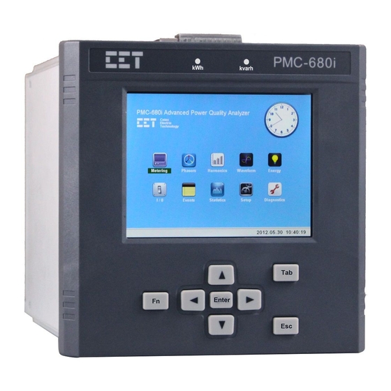
Page 34: Navigating The Front Panel User Interface
3.1.2 Navigating the Front Panel User Interface Figure 3-4 Front Panel User Interface The PMC-680i features a stunning, high resolution, color LCD display with an intuitive graphical user interface that makes it extremely simple to operate. There are eight buttons located beneath the LCD display on the front panel: <Enter>, <Tab>, <Fn>,... - Page 35 Ceiec Electric Technology The following table gives a complete description of this information hierarchy. Category Topics Pages Metering Real Time...
- Page 36 Ceiec Electric Technology Fundamental Power Quality Phasors Ua Distortion Harmonics Ia Distortion...
- Page 37 Ceiec Electric Technology Ua RMS Ia RMS Harmonic Pa Harmonic Qa Ua Harmonic Phase Angle Ia Harmonic Phase Angel Ua Interharmonic Distortion Ia Interharmonic Distortion Ua Interharmonic Ia Interharmonic...
- Page 38 Ceiec Electric Technology Waveform Total Energy Energy Harmonic Energy Demand...
- Page 39 Ceiec Electric Technology...
- Page 40 Ceiec Electric Technology TOU Log...
- Page 41 Ceiec Electric Technology Events PQ Log PQ Event Counter Statistics EN50160...
- Page 42 Ceiec Electric Technology...
- Page 43 Ceiec Electric Technology Max. Min. SDR Trend Basic Setup COMM...
-
Page 44: Web Interface
Table 3-2 Description of each Hierarchy 3.2 Web Interface The PMC-680i's web interface has been designed specifically to work with Google Chrome. Please use this link (https://www.google.com/intl/en/chrome/browser/) to download and install Google Chrome if it's not already installed on the PC. -
Page 45: Setting Pc's Ip Address
Figure 3-6 Setting PC’s IP Address 3.2.2 Configure PMC-680i's IP Addresses To configure the PMC-680i's IP Addresses, move the cursor to the Setup category, hit <Enter> and then the Basic Setup topic appears. Hit the <Tab> button to move from Basic Setup to COMM Setup. -
Page 46: Enabling Java Scripting In Google Chrome
Ceiec Electric Technology Figure 3-7 Configure PMC-680i’s IP Address 3.2.3 Enabling Java Scripting in Google Chrome Open Google Chrome with Java scripting enabled. To enable Java Scripting, move the mouse pointer to the upper right-hand corner of the Google Chrome interface and then click on this icon to open the Settings page. -
Page 47: Web Interface
Figure 3-10 Set Content Setting for Google Chrome 3.2.4 Web Interface Enter the IP Address of the PMC-680i in the Address area of Google Chrome and then press <Enter>. The PMC-680i’s Web Interface appears. There are four main menu items on the left-hand pane - Metering, Statistics, Setup and Diagnostics. - Page 48 Ceiec Electric Technology Click on the down arrow icon on the right of Metering to expand its sub-menu, which includes Phasors, Real Time, Power Quality, Harmonics, Interharmonics, Demand, Energy, TOU, Waveform and I/O. The following sections provide a quick overview of the web pages available under Metering.
- Page 49 Ceiec Electric Technology Figure 3-13 Real Time Interface 3.2.4.1.3 Power Quality Click Power Quality on the left-hand pane, the available outputs are Voltage Deviation, Frequency Deviation, Flicker, Symmetrical Components, Unbalance and PQ Event Counter. Figure 3-14 Power Quality Interface 3.2.4.1.4 Harmonics Click on the drop-down box beside Harmonics on the right-hand pane to select which input to display.
- Page 50 Ceiec Electric Technology Figure 3-15 Harmonics Interface 3.2.4.1.5 Interharmonics Click on the drop-down box beside Inter-Harmonics on the right-hand pane to select which input to display. The available inputs are Ua (WYE)/Uab (Delta), Ub (WYE)/Ubc (Delta), Uc (WYE)/Uca (Delta), U4, Ia, Ib, Ic, I4 and I5. Click Interharmonic Distortion (%) and Interharmonic RMS (V) to view corresponding information.
- Page 51 Ceiec Electric Technology Figure 3-17 Demand Interfaces 3.2.4.1.7 Energy Click Energy on the left-hand pane, the Total Energy and Harmonic Energy will be shown on the right- hand pane. Click Total Energy tab, the available outputs are Active/Reactive/Apparent Energy, while Harmonic Energy displays H01 to H63 kWh Imp./Exp., H01 to H63 kvarh Imp./Exp.
- Page 52 Figure 3-19 TOU Interfaces 3.2.4.1.9 Waveform This web page displays the real-time waveform captured by the PMC-680i. A small fly-out comment showing the channel name and the measurement value is displayed when the mouse pointer is positioned to a particular point in a waveform.
- Page 53 Ceiec Electric Technology Click on the down arrow icon beside Statistics on the right to expand its sub-menu, which includes Counters, SOE, PQ Log, Max./Min., SDR Trend, PQDIF, COMTRADE and EN50160. The following sections provide a quick overview of the web pages available under Statistics. 3.2.4.2.1 Counters This web page displays counters for SOE, PQ log, Pst, Plt, TOU, IER, EN50160, WFR, DWR, MSV, DR, HSDR and SDR.
- Page 54 Ceiec Electric Technology Figure 3-23 SOE Interface and Download Waveform file 3.2.4.2.3 PQ Log This web page displays PQ Log starting with the most recent event (with a Start Index of 1). There is a text box near the lower right-hand corner of the page. By entering a specific value in the text box and the web page jump to particular page.
- Page 55 Ceiec Electric Technology 3.2.4.2.5 SDR Trend Click SDR Trend on the left-hand pane and the following screen appears on the right-hand pane. This web page displays the Statistical Log in a trend curve. The available inputs are FREQ, Ua, Ub, Uc, U4, Ia, Ib, Ic, I4, I5, Ua ANG, Ub ANG which can be configured via communication, please refer to 5.9.20 Trend Log Setup.
- Page 56 Ceiec Electric Technology Figure 3-27 PQDIF Interface 3.2.4.2.7 COMTRADE Click on COMTRADE on the left-hand pane and the following screen appears on the right-hand pane. This web page displays the available COMTRADE files in a Table format. The view button below Waveform column allows the user to view waveform of the COMTRADE file.
- Page 57 Ceiec Electric Technology Figure 3-29 EN50160 Interface Figure 3-30 Detail Information Example 3.2.4.3 Setup Click Setup on the left-hand pane to expand and the sub-menus, which includes Basic Setup, PQ Setup, Demand Setup, Record Setup, I/O Setup, COMM Setup, Clock Setup, Password Setup and Clear.
- Page 58 The user then enter the password (default password = 000000) at the Login dialog box. The user may now make the necessary setup changes for the PMC-680i. 3.2.4.3.1 Basic Setup Click Basic Setup on the left-hand pane and the following screen appears on the right-hand pane.
- Page 59 Ceiec Electric Technology Ia Reverse Normal, Ib Reverse Normal, Reverse Ic Reverse Normal, Reverse Reverse I4 Reverse I5 Reverse Calculation PF Convention IEC, IEEE, -IEEE kVA Calculation Vector, Scalar Others Basic Agg. 50cyc, 150cyc, 10min, 2 Freq. Agg 1sec, 3sec, 10sec PQ Plot ITIC, SEMI F47 Phase A Color...
- Page 60 Ceiec Electric Technology Figure 3-33 PQ Setup Interface 3.2.4.3.3 Demand Setup Click Demand Setup on the left-hand pane and the following screen appears. Set demand parameters as you need, please refer to 5.9.8 Demand Setup.
- Page 61 Ceiec Electric Technology Figure 3-34 Demand Setup Interface 3.2.4.3.4 Energy Setup Click Energy Setup on the left-hand pane and the following screen appears. Set energy parameters as you need, please refer to 5.9.17 Interval Energy Recorder (IER) Setup and 5.9.10 Energy Pulse Setup.
- Page 62 Figure 3-37 I/O Setup Interface 3.2.4.3.7 COMM Setup The PMC-680i comes standard with two Ethernet ports (P1&P2) which support Modbus TCP and two RS-485 ports (P3&P4) which support Modbus RTU. In addition, PMC-680i support sending alarm email via setting SMTP server. Click on COMM Setup on the left-hand pane and the following screen appears.
- Page 63 Figure 3-39 Clock Setup Interface 3.2.4.3.9 Password Setup Click Password Setup on the left-hand pane and the following screen appears. This web page allows the user to change the Login password for the PMC-680i. It's highly recommended for the user to...
- Page 64 Ceiec Electric Technology change the default Login password to something unique. After inputting passwords, click Save to save change. Figure 3-40 Password Setup Interface 3.2.4.3.10 Clear Click Clear on the left-hand pane and the following screen appears. This web page allows the user to perform the following Clear functions: Button Function...
- Page 65 Click Diagnostics on the left-hand pane to expand its sub-menu, which includes Diagnostics and Maintenance. 3.2.4.5.1 Diagnostics Click Diagnostics on the left-hand pane and the following screen appears. This web page displays the PMC-680i's diagnostics information in a table format, which includes Version, Self Diagnostics, Memory and Site Information. Figure 3-43 Diagnostics Interface...
- Page 66 Ceiec Electric Technology 3.2.4.4.2 Maintenance User login the PMC-680i Web with standard password, and click Maintenance on the left-hand pane and the following screen appears. Backup & Restore Save or restore all configuration to local Alarm E-mail Test...
-
Page 67: Chapter 4 Applications
Chapter 4 Applications 4.1 Inputs and Outputs 4.1.1 Digital Inputs The PMC-680i is equipped with 8 self-excited Digital Inputs (DIs) that are internally wetted at 24 VDC. Each DI has the following setup parameters: Setup Parameter Definition Options Each DI can be configured as a Status Input, Pulse Counter Input. - Page 68 Ceiec Electric Technology 2= -ve Transition DIx Setpoint Trigger See Table 5-92 See Table 5-92 DIx Pulse Weight Table 4-2 DI Setup Parameters for Status Input Figure 4-1 Program DI for Status Monitoring 2) A DI can be used for pulse counting to collect WAGES (Water, Air, Gas, Electricity and Steam) information.
-
Page 69: Relay Outputs And Digital Outputs
4.1.2 Relay Outputs and Digital Outputs The PMC-680i comes standard with 2 Form A and 2 Form C Mechanical Relay Outputs (RO) as well as 4 Solid State Relay Outputs (DO). RO and DO are normally used for setpoint alarming, load control, or remote control applications. - Page 70 Figure 4-4 Manual Operation of RO/DO via the Front Panel Interface Since there are so many ways to utilize the relay output on the PMC-680i, a prioritized scheme has been developed to avoid conflicts between different applications. In general, Front Panel Control...
-
Page 71: Energy Pulse Outputs
Providing energy consumption information to an external device such as a PLC or a Pulse Counter The PMC-680i can be configured to generate kWh and/or kvarh energy pulsing via either the 2 Front Panel LED Pulse Outputs (kWh and kvarh) or the 4 Digital Outputs in the back. Energy pulsing can be enabled from the Front Panel or Web through the Demand Energy or Energy Setup screen. -
Page 72: Power, Energy And Demand
1000 1000 Table 4-9 Settings for Energy Pulse Constant 4.2 Power, Energy and Demand 4.2.1 Basic Measurements The PMC-680i provides the following basic measurements with 1 second update rate: 3-phase Voltages and Currents 3-phase Powers, PFs and dPF ... -
Page 73: Energy Measurements
Figure 4-6 Displaying for Basic Measurements 4.2.2 Energy Measurements The PMC-680i provides Energy measurements include fundamental energy as well as harmonic energy. The energy has a maximum value of 99,999,999,999.999 and will roll over to zero when it is reached. The energy can be reset manually or preset to user-defined values through the front panel or via communications. - Page 74 Sync. The predicted demand is typically used for pre-alarm and helps users reducing power consumption. PMC-680i also provides recording of Max. Demand of this month and last month. The Max. Demand of this month can be transferred to be as Max. Demand of last month at the end of month, and the Max.
- Page 75 Ceiec Electric Technology Ia/Ib/Ic I avg ∑kVA kWa/kWb/kWc kvara/kvarb/kvarc ∑kW Imp./Exp. ∑kvar Imp./Exp. kVAa/kVAb/kVAc Imp./Exp. Imp./Exp. Ua/Ub/Uc Uab/Ubc/Uca P.F.a/P.F.b/P.F.c ∑P.F. Frequency Deviation Deviation Ua/Ub/Uc Over Uab/Ubc/Uca Over Ua/Ub/Uc Under Uab/Ubc/Uca Freq Deviation Deviation Deviation Deviation Under Deviation U2/U0 Unbalance I2/I0 Unbalance Ia/Ib/Ic K Factor I4 K Factor I5 K Factor...
-
Page 76: Time Of Use (Tou)
The PMC-680i supports two TOU schedules, which can be switched at a pre-defined time. The switching between the two schedules is stored in the SOE log as an event. Up to twelve seasons can be applied and each season can be programmed with up to twenty daily profiles for alternative day, weekday1, weekday2 or weekday3. - Page 77 Figure 4-10 TOU Status For each Tariff, the PMC-680i provides the following real-time Energy and Demand information: kWh/kvarh Imp./Exp., kVAh and kW/kvar Imp./Exp. Max. Demands. The register value will roll over to zero automatically when it reaches 99,999,999,999.999 kWh.
-
Page 78: Setpoints
Ceiec Electric Technology In addition, PMC-680i provides real-time datalog, historic datalog and transient datalog for TOU. Each datalog contains energy and demand information. The real-time datalog triggered by fixed time automatically and transient datalog triggered manually. The real-time datalog has a capacity of 3 entries organized in a FIFO basis, with the newest datalog replacing the oldest one. - Page 79 Ceiec Electric Technology Figure 4-12 Under Setpoints The Setpoints can be programmed over communications and have the following setup parameters: Setup Parameter Definition Options 0*=Over Setpoint Setpoint Type Specify the monitoring condition -- Over Setpoint, Under Setpoint. 1=Under Setpoint Setpoint Parameter Specify the parameter to be monitored.
- Page 80 Ceiec Electric Technology stored in the SOE Log. The range of the Setpoint Inactive Delay is between 0 and 9999 seconds for Standard Setpoints and between 0 and 9999 cycles for High Setpoints. Setpoint Trigger Specify what action a setpoint can take when it becomes active. Please refer to Table 4-16 below for a list of Setpoint Triggers.
-
Page 81: Power Quality Parameters
Table 4-16 Setpoint Triggers 4.4 Power Quality Parameters The PMC-680i has been certified as an IEC 61000-4-30 Class A performance instrument by PSL. Therefore, the Measurement Aggregation Algorithm used for the derivation of all IEC 61000-4-30 PQ parameters are in accordance to Section 4.5 of the IEC 61000-4-30 Standard. Please refer to Appendix E for a copy of the IEC 61000-4-30 Class A Certificate of Conformity. -
Page 82: Supply Voltage Dips/Swells And Interruption
"output 4 and 5 values" (see IEC 61000-4-15) to be flagged. Please refer to Section 4.4.12 Flagging Concept for a detailed description. The PMC-680i is capable of storing Flicker measurements for 1 year with the standard 4GB model and 2 years with the 8GB option. - Page 83 Ceiec Electric Technology The difference between the Reference Voltage (either U or U ) and the Residual Voltage. It's Depth generally expressed in percentage of the Reference Voltage. Duration The time difference between the beginning and the end of the Voltage Dip. Table 4-17 Dip Evaluation Parameter 4.4.4.2 Voltage Swell Evaluation A Voltage Swell is characterized by a pair of data, the Maximum Swell Voltage Magnitude and...
- Page 84 Ceiec Electric Technology 101 to 200(%) of reference voltage, Swell Limit Specify the limit of Swell. Default=110% 1 to 99(%) of reference voltage, Dip Limit Specify the limit of Dip. Default=90% Dip Return 1 to 1000 (x0.001 Ue), Default=5 Specify the return value of Dips. Swell Return 1 to 1000 (x0.001 Ue), Default=5 Specify the return value of Swells.
- Page 85 Ceiec Electric Technology Figure 4-17 RMS Plot of the same Dip Event 4.4.4.6 Voltage Interruption Evaluation On polyphase systems, a Voltage Interruption begins when the U voltages of all channels fall rms (1/2) below the Interruption Threshold and ends when the U voltage on any one channel is equal to, rms (1/2) or greater than, the Interruption Threshold plus the Hysteresis.
-
Page 86: Voltage Transients
Ceiec Electric Technology 4.4.5 Voltage Transients The PMC-680i provides the capability for detecting voltage transient disturbances using the sliding- window method according to IEC 61000-4-30 with a maximum resolution of 40µs (@50Hz) for the standard PMC-680i and 20µs (@50Hz) with the optional 1024 samples/cycle sampling. The PMC- 680i provides transient detection for voltage quality monitoring and records an event in the PQ Log, which includes the event timestamp event type, and event characteristics. -
Page 87: Harmonics And Interharmonics
Nominal Voltage Current K Harmonic /Interharmonic Distortion= X100% where I is the Nominal Current The PMC-680i also provides, in addition to Voltage Harmonics, measurements for Current Harmonics, K-Factor, Crest Factor, Power Harmonics and Energy Harmonics. K-Factor and Crest Factor... - Page 88 ▪ ▪ Phase Angle H01 to H63 ▪ ▪ ▪ ▪ ▪ ▪ ▪ ▪ ▪ Table 4-22 Voltage and Current Harmonics and Interharmonics Measurements 4.4.8.2 Power Harmonics The following table illustrates the Power Harmonic measurements available on the PMC-680i:...
-
Page 89: Mains Signalling Voltage (Msv)
Ceiec Electric Technology kW/kvar/kVA TH ▪ ▪ ▪ ▪ ▪ ▪ PF TH kW/kvar/kVA Fundamental ▪ ▪ ▪ ▪ ▪ ▪ PF Fundamental ▪ ▪ ▪ ▪ ▪ ▪ kW/kvar/kVA H02 to H63 ▪ ▪ ▪ ▪ ▪ ▪ PF H02 to H63 ▪... -
Page 90: Voltage Deviation
120s. The PMC-680i provides 3 groups of waveform recorder for MSV with 128 entries in accordance with Section 5.10 of IEC 61000-4-30 Standard for Class A performance. Each MSV WR will be recorded as PQ Log, SOE Log and EN50160 report. -
Page 91: Rapid Voltage Changes (Rvc)
≤ U under The PMC-680i is capable of measuring Voltage accurate to 0.1% and monitoring Voltage deviation on line. In addition, the Voltage deviation can be set as setpoint. The following screen captures illustrates the display of the Deviation parameters in the Front Panel and built-in Web Interface. - Page 92 Ceiec Electric Technology Figure 4-22 Rapid Voltage Changes The RVC Setpoint provides the following setup parameters which can be programmed through the Front Panel, web or over communications: Setup Parameters Definition Options RVC Enable Specifies if RVC Setpoint is enabled. Disabled* / Enabled 0*= Steady-state Volt.
-
Page 93: Inrush Current
Ceiec Electric Technology Figure 4-23 RVC Setup via Front Panel and Web 4.4.10.2 WFR of RVC Event Figure 4-24 WFR of a RVC Event Figure 4-25 RMS Plot of the same RVC Event 4.4.11 Inrush Current As per IEC 61000-4-30:... - Page 94 Figure 4-26 Inrush Current The PMC-680i provides the capability for detecting and the capturing of the inrush current transient disturbance that is in accordance with the IEC 61000-4-30 Standard for Class A performance.
- Page 95 Ceiec Electric Technology Table 4-27 Setup Parameters for Inrush Current Setpoint Table 4-27 Setup Inrush Current Setpoint via Front Panel and Web 4.4.11.2 WFR of Inrush Current Event Figure 4-28 WFR of an Inrush Current Event @ 128 samples/cycle Figure 4-29 WFR of an Inrush Current Event @ 512 samples/cycle...
-
Page 96: Flagging Concept
The PMC-680i is a certified IEC 61000-4-30 Class A device so it supports the Flagging Concept. Flagging Setup... -
Page 97: Disturbance Direction Location
When the Dip starts, the PMC-680i start detect location automatically and provide confidence by calculating power characters, and the direction information and the confidence level are recorded as PQ Log. -
Page 98: Disturbance Waveform Recorder (Dwr)
EN50160 Report can be accessed through the Front Panel or via communications. The PMC-680i can store up to 52 logs, if there are more than 52 logs, the newest log will replace the oldest on a FIFO basis. - Page 99 Ceiec Electric Technology of power failure. The PMC-680i can store DWR logs up to 128 entries @4GB or 256 entries @8GB. Each disturbance waveform recording consists of the following stages. Figure 4-32 Disturbance Location Stage Description Recording Length Recording Frequency...
-
Page 100: Itic/Semi F47 Curve
ITIC SEMI F47 Figure 4-35 ITIC and SEMI F47 PMC-680i’s Front Panel or Web can display ITIC or SEMI F47 curve for PQ Events. Display ITIC or SEMI F47 can be set via the Web or communication. Setup Parameters Definition Options Set display ITIC or SEMI F47 curve for PQ event. -
Page 101: Data Logging
4.5 Data Logging 4.5.1 SOE Log and PQ Log The PMC-680i’s SOE Log and PQ Log can store up to 1024 events. The SOE Log consists of such events as power-on, power-off, PQ events, Discrete Events, setpoint actions, WFR, Mains Signaling... - Page 102 Ceiec Electric Technology Figure 4-38 SOE/PQ Log, Waveform and ITIC Curve Please follow guidelines below to open waveform or ITIC/SEMI F47 curve of the event. 1. On the SOE/PQ Log page, select SOE/PQ log page by pressing 2. On the one page, select an event by pressing 3.
-
Page 103: Statistical Data Recorder (Sdr)
4.5.3 Data Recorder (DR) The PMC-680i provides 8 Standard Data Recorders with recording interval from 1s to 40 days and 4 HS Data Recorders with recording interval from 0.5 to 60 cycles, each recorder supports 16 parameters. -
Page 104: Max./Min. Log
Under Stop-When-Full mode, the record would be stop when the storage is full. 4.5.4 Max./Min. Log The PMC-680i provides 4 Max. Logs and 4 Min. Logs capable of recording 20 parameters each since Last Reset (This Month) or before Last Reset (Last Month). Each record includes relevant parameter values and timestamp. -
Page 105: Pst Log
Figure 4-40 Clear All Max./Min. Log 4.5.5 Pst Log The PMC-680i’s Pst Log can store up to 52560 events per 10 minutes about voltage Pst in its non- volatile memory. Each event record includes the event classification, its relevant parameter values and a timestamp in 1ms resolution. - Page 106 Exp. TH Table 4-37 IER Measurements The PMC-680i with the standard 4GB option can can store 65535 records. If the storage is full, the newest event will replace the oldest event on a first-in-first-out basis. The IER Logs can be reset from the Front panel or via communications.
-
Page 107: Qualification Rate Log
Table 4-39 Setup Parameters for Qualification Rate Log 4.5.9 Waveform Recorder (WFR) The PMC-680i provides one group of WFR with a total of 128 entries @4GB or 256 entries @8GB. WFR Log can simultaneously capture 3-phase voltage and current signals at a maximum resolution of 128/256 samples per cycles. -
Page 108: Sdr Trend
PMC Setup Software for display. 4.5.10 SDR Trend The PMC-680i provides trend curve for Max./Min., Avg. and CP95 with up to 12 parameters including voltage, current, power, energy, etc. using SDR log. It’s important to note that because data source of parameters are come from SDR Log, the parameter that used to draw trend curve should be configured in SDR. -
Page 109: Pqdif And Comtrade Storage
All record can be stored for about half a year without communication and will not suffer any loss in the event of a power failure. The PMC-680i can store following standard data with PQDIF format. -
Page 110: Pq Counters
Ceiec Electric Technology Ia/Ib/Ic_H01_RMS ... Ia/Ib/Ic_H63_RMS 150/180 cycles Ua/Ub/Uc_TIHD, Ua/Ub/Uc_TOIHD, Ua/Ub/Uc_TEIHD 150/180 cycles Inter-Harmonic Voltage Ua/Ub/Uc_IHD_01 ... Ua/Ub/Uc_IHD_63 150/180 cycles Ia/Ib/Ic_TIHD, Ia/Ib/Ic_TOIHD, Ia/Ib/Ic_TEIHD 150/180 cycles Inter-Harmonic Current Ia/Ib/Ic_IH01_RMS ... Ia/Ib/Ic_IH63_RMS 150/180 cycles 10 mines Flicker 2 hours kWa/kWb/kWc, kvara/kvarb/kvarc, kVAa/kVAb/kVAc, Fundamental Power 150/180 cycles DFa/DFb/DFc, ∑kW, ∑kvar, ∑kVA... -
Page 111: Smtp (Simple Mail Transfer Protocol)
Figure 4-45 Clear PQ Event Counters through Front Panel and Web 4.6 SMTP (Simple Mail Transfer Protocol) SMTP can be used to send PMC-680i’s PQ or SOE email notification to specified mail address through the connected Ethernet port providing that the network and SMTP Sever has been properly configured. - Page 112 Ceiec Electric Technology Login Password The login password of the source Email Address. Destination Email Address Determines an email address will receive SOE/PQ log notification. Table 4-44 SMTP Setup Parameters Notes: SMTP Event Classification register determines if a newly generated SOE/PQ LOG is sent out by email. The following table illustrates the Bitmap definition of this register.
- Page 113 Ceiec Electric Technology Figure 4-46 Setup SMTP via Web Please follow guidelines below to use alarm email notification function of the PMC-680i: Configure Ethernet via the Front Panel, make sure the Ethernet settings are correct and can access to the internet.
-
Page 114: Time Synchronization
Notes: Please remember to shut down anti-spam function in both Receiver and Sender Email sides. The Email Format is fixed. Only device name and time format can be modified in PMC-680i Web interface. 4.7 Time Synchronization The PMC-680i is equipped with a 6ppm, battery-backed real-time clock that has a maximum error of 0.5s per day. -
Page 115: Pecstar Iems
SNTP can be used to synchronize the PMC-680i's clock through the connected Ethernet port providing that the network has been properly configured for the PMC-680i to connect to the SNTP Server, wherever it resides. The programming of the SNTP setup parameters are supported via the Front Panel or communications. -
Page 116: Gps With Time Sync Pulse
Table 4-53 Relation with Terminal 4.7.6 IRIG-B The PMC-680i can be configured to synchronize its clock with an IRIG-B input with P1 (RS485 Port #1). The IRIG-B can analysis from year to second information and synchronize clock to millisecond without other ways. -
Page 117: Di With Pps
Ceiec Electric Technology 4.7.7 DI with PPS The PMC-680i can be configured to synchronize its millisecond clock with 1PPS output via one of PMC-680i’s DI8. The programming of the DI is only supported over communications. The time synchronization with DI provides the following setup parameters. -
Page 118: Chapter 5 Modbus Register Map
Chapter 5 Modbus Register Map This chapter provides a complete description of the Modbus register map (Protocol Version 3.0) for the PMC-680i Advanced Utility Power Quality Analyzer to facilitate the development of 3 party Modbus RTU communications driver for accessing information on the PMC-680i. - Page 119 Ceiec Electric Technology 0034 kvarb Float 0036 kvarc Float 0038 ∑kvar Float 0040 kVAa Float 0042 kVAb Float 0044 kVAc Float 0046 ∑kVA Float 0048 P.F.a Float 0050 P.F.b Float 0052 P.F.c Float 0054 ∑P.F. Float 0056 FREQ Float 0058 Float 0060 Float...
- Page 120 Ceiec Electric Technology 0097 Standard Setpoint Status #3 Bitmap 0099 Standard Setpoint Status #4 Bitmap 0101 Standard Setpoint Status #5 Bitmap 0103 Standard Setpoint Status #6 Bitmap 0105 Standard Setpoint Status #7 Bitmap 0107 Standard Setpoint Status #8 Bitmap 0109 Reserved 0111 HS Setpoint Status...
- Page 121 Ceiec Electric Technology 0155 MSV WFR Pointer (Freq #2) UINT32 0157 MSV WFR Pointer (Freq #3) UINT32 0159 SDR Log #1 Pointer UINT32 0161 SDR Log #2 Pointer UINT32 0163 SDR Log #3 Pointer UINT32 0165 SDR Log #4 Pointer UINT32 0167 SDR Log #5 Pointer...
- Page 122 Ceiec Electric Technology 0223 HS DR Log #1 Pointer UINT32 0225 HS DR Log #2 Pointer UINT32 0227 HS DR Log #3 Pointer UINT32 0229 HS DR Log #4 Pointer UINT32 0231~0237 Reserved 0239 Pst Log Pointer UINT32 0241 Plt Log Pointer UINT32 0243 Reserved...
- Page 123 Ceiec Electric Technology Reserved Reserved * 2xIn Table 5-2 Flagging Status The Standard Setpoint Status #1 to #8 registers represent the states of Standard Setpoints #1 to #256 while the HS Setpoint Status register represents the states of HS Setpoints #1 to #16, with a bit value of 1 meaning active and 0 meaning inactive.
- Page 124 SOE / PQ log generated and will roll over to 0 if its current value is 0xFFFFFFFF. Since the SOE /PQ Log Pointer is a 32-bit value and the SOE / PQ Log capacity is relatively small with only 1024 entries in the PMC-680i, an assumption has been made that the SOE / PQ Log pointer will never roll over.
-
Page 125: Energy Measurements
Ceiec Electric Technology 5.2 Energy Measurements Register Address Property Description Format Unit 0500 kWh Imp. INT64 0504 kWh Exp. INT64 0508 kvarh Imp. INT64 varh 0512 kvarh Exp. INT64 varh 0516 kVAh Total INT64 0520 kWh Net INT64 0524 kWh Total INT64 0528 kvarh Net... -
Page 126: Pq Measurements
Ceiec Electric Technology For example, Bottom Value is 999,999,995, New Integrated Value is 8, and then the value after rolling over is: 999,999,995 + 8 – 1,000,000,000 = 3 5.4 PQ Measurements Register Address Property Description Format Unit 0700 Ua Deviation Float 0702 Ub Deviation... - Page 127 Ceiec Electric Technology 0748 Uc (WYE) / Uca (Delta) Fluctuation Freq. Float 0750 U0 Unbal. Float 0752 U2 Unbal. Float 0754 I0 Unbal. Float 0756 I2 Unbal. Float 0758 Float 0760 Float 0762 Float 0764 Float 0766 Float 0768 Float 0770 Ua (WYE) / Uab (Delta) Pst.
- Page 128 Ceiec Electric Technology 0802 I5 TDD Odd Float 0804 Ia TDD Even Float 0806 Ib TDD Even Float 0808 Ic TDD Even Float 0810 I4 TDD Even Float 0812 I5 TDD Even Float 0814 Ia K-Factor Float 0816 Ib K-Factor Float 0818 Ic K-Factor...
-
Page 129: Harmonics & Interharmonic Measurements
Ceiec Electric Technology 0856 Ub (WYE) / Ubc (Delta) MSV #3 Float 0858 Uc (WYE) / Uca (Delta) MSV #3 Float Table 5-16 PQ Measurements Notes: When the Wiring Mode is Delta, the per phase line-to-neutral voltage deviations have no meaning, and their registers are reserved Please refer to Section 4.4.9 Voltage Deviation for a detailed description. - Page 130 Ceiec Electric Technology 1036 Ua (WYE) / Uab (Delta) TEHD Float % / x100 1038 Ub (WYE) / Ubc (Delta) TEHD Float % / x100 1040 Uc (WYE) / Uca (Delta) TEHD Float % / x100 1042 U4 TEHD Float % / x100 1044 Ia TEHD...
-
Page 131: Harmonic Voltage & Current Rms
Ceiec Electric Technology … … … % / x100 2188 Ua (WYE) / Uab (Delta) HD63 Float % / x100 2190 Ub (WYE) / Ubc (Delta) HD63 Float % / x100 2192 Uc (WYE) / Uca (Delta) HD63 Float % / x100 2194 U4 HD63 Float... - Page 132 Ceiec Electric Technology 2326 Ia TOH01 RMS Float 2328 Ib TOH01 RMS Float 2330 Ic TOH01 RMS Float 2332 I4 TOH01 RMS Float 2334 I5 TOH01 RMS Float 2336 Ua (WYE) / Uab (Delta) TEH01 RMS Float 2338 Ub (WYE) / Ubc (Delta) TEH01 RMS Float 2340 Uc (WYE) / Uca (Delta) TEH01 RMS...
-
Page 133: Individual Total Harmonic
Ceiec Electric Technology 2380 Ia H01 RMS Float 2382 Ib H01 RMS Float 2384 Ic H01 RMS Float 2386 I4 H01 RMS Float 2388 I5 H01 RMS Float … … … … 3488 Ua (WYE) / Uab (Delta) H63 RMS Float 3490 Ub (WYE) / Ubc (Delta) H63 RMS... -
Page 134: Harmonic Power
Ceiec Electric Technology 27496 TH63 Float 27498 kvar TH63 Float 27500 TH63 Float 27502 P.F. TH63 Float Table 5-19 Individual Total Harmonic Notes: When the Wiring Mode is Delta, the per-phase kW/kvar/kVA H01 to H63 have no meaning, and their registers are reserved. -
Page 135: Harmonic Angles
Ceiec Electric Technology 28046 kvara H01 Float 28048 kvarb H01 Float 28050 kvarc H01 Float 28052 kVAa H01 Float 28054 kVAb H01 Float 28056 kVAc H01 Float 28058 P.F.a H01 Float 28060 P.F.b H01 Float 28062 P.F.c H01 Float … …... -
Page 136: Harmonic Energy
Ceiec Electric Technology 30000~30016 Reserved Float 30018 Ua(WYE) / Uab(Delta) Angle H01 Float 30020 Ub(WYE) / Ubc(Delta) Angle H01 Float 30022 Uc(WYE) / Uca(Delta) Angle H01 Float 30024 U4 Angle H01 Float 30026 Ia Angle H01 Float 30028 Ib Angle H01 Float 30030 Ic Angle H01... -
Page 137: Interharmonics Distortion (Ihd) Measurements
Ceiec Electric Technology 31516 kWh Net TH Int64 31520 kWh Total TH Int64 31524 kvarh Net TH Int64 varh 31528 kvarh Total TH Int64 varh 31532 31600 kWh Imp. H01 Int64 31604 kWh Exp. H01 Int64 31608 kvarh Imp. H01 Int64 varh 31612... - Page 138 Ceiec Electric Technology 33110 Ib TIHD Float %, x100 33112 Ic TIHD Float %, x100 33114 I4 TIHD Float %, x100 33116 I5 TIHD Float %, x100 33118 Ua / Uab TOIHD Float %, x100 33120 Ub / Ubc TOIHD Float %, x100 33122...
-
Page 139: Interharmonic Voltage & Current Rms
Ceiec Electric Technology 33164 Ib IHD01 Float %, x100 33166 Ic IHD01 Float %, x100 33168 I4 IHD01 Float %, x100 33170 I5 IHD01 Float %, x100 … … …. … 34288 Ua / Uab IHD63 Float %, x100 34290 Ub / Ubc IHD63 Float... - Page 140 Ceiec Electric Technology 34516 I5 TIH RMS Float 34518 Ua (WYE) / Uab (Delta) TOIH RMS Float 34520 Ub (WYE) / Ubc (Delta) TOIH RMS Float 34522 Uc (WYE) / Uca (Delta) TOIH RMS Float 34524 U4 TOIH RMS Float 34526 Ia TOIH RMS Float...
-
Page 141: Demand
Ceiec Electric Technology 34570 I5 IH00 RMS Float 34572 Ua (WYE) / Uab (Delta) IH01 RMS Float 34574 Ub (WYE) / Ubc (Delta) IH01 RMS Float 34576 Uc (WYE) / Uca (Delta) IH01 RMS Float 34578 U4 IH01 RMS Float 34580 Ia IH01 RMS Float... - Page 142 Ceiec Electric Technology 3606 ULN Avg Float 3608 Float 3610 Float 3612 Float 3614 Float 3616 ULL Avg. Float 3618 Float 3620 Float 3622 Float 3624 I Avg. Float 3626 Float 3628 Float 3630 kWa Imp. Float 3632 kWb Imp. Float 3634 kWc Imp.
- Page 143 Ceiec Electric Technology 3660 ∑kvar Exp. Float 3662 kVAa Float 3664 kVAb Float 3666 kVAc Float 3668 ∑kVA Float 3670 P.F.a Float 3672 P.F.b Float 3674 P.F.c Float 3676 ∑P.F. Float 3678 Freq Float 3680 Ua Deviation Float 100% 3682 Ub Deviation Float 100%...
- Page 144 Ceiec Electric Technology 3714 Uca Under Deviation Float 100% 3716 Freq. Deviation Float 100% 3718 U0 Unbal. Float 3720 U2 Unbal. Float 3722 I0 Unbal. Float 3724 I2 Unbal. Float 3726 Ia K-Factor Float 3728 Ib K-Factor Float 3730 Ic K-Factor Float 3732 I4 K-Factor...
-
Page 145: Predicted Demand
Ceiec Electric Technology 3768 I4 TOHD Float 3770 I5 TOHD Float 3772 Ua (WYE) / Uab (Delta) TEHD Float 3774 Ub (WYE) / Ubc (Delta) TEHD Float 3776 Uc (WYE) / Uca (Delta) TEHD Float 3778 U4 TEHD Float 3780 Ia TEHD Float 3782... - Page 146 Ceiec Electric Technology 3910 Float 3912 Float 3914 Float 3916 ULL Avg. Float 3918 Float 3920 Float 3922 Float 3924 I Avg. Float 3926 Float 3928 Float 3930 kWa Imp. Float 3932 kWb Imp. Float 3934 kWc Imp. Float 3936 ∑kW Imp.
-
Page 147: Max. Value Per Demand Period
Ceiec Electric Technology 3964 kVAb Float 3966 kVAc Float 3968 ∑kVA Float 3970 P.F.a Float 3972 P.F.b Float 3974 P.F.c Float 3976 ∑P.F. Float 3978 Freq Float Table 5-26 Predicted Demand Notes: When the Wiring Mode is Delta, the per phase V/kW/kvar/kVA/PF Predicted demand have no meaning, and their registers are reserved. - Page 148 Ceiec Electric Technology 4184 4190 kWa Imp. 4196 kWb Imp. 4202 kWb Imp. 4208 ∑kW Imp. 4214 kWa Exp. Float 4220 kWb Exp. Float 4226 kWb Exp. Float 4232 ∑kW Exp. Float 4238 kvara Imp. 4244 kvarb Imp. 4250 kvarb Imp. Note 2) 4256 ∑kvar Imp.
- Page 149 Ceiec Electric Technology 4346 Ub Deviation 100% 4352 Uc Deviation 100% 4358 Uab Deviation 100% 4364 Ubc Deviation 100% 4370 Uca Deviation 100% 4376 Ua Over Deviation 100% 4382 Ub Over Deviation 100% 4388 Uc Over Deviation 100% 4394 Uab Over Deviation 100% 4400 Ubc Over Deviation...
- Page 150 Ceiec Electric Technology 4508 Ua (WYE) / Uab (Delta) THD 4514 Ub (WYE) / Ubc (Delta) THD 4520 Uc (WYE) / Uca (Delta) THD 4526 U4 THD 4532 Ia THD 4538 Ib THD 4544 Ic THD 4550 I4 THD 4556 I5 THD 4562 Ua (WYE) /Uab (Delta) TOHD...
-
Page 151: Min. Value Per Demand Period
Ceiec Electric Technology 4670 Ia H01 4676 Ib H01 4682 Ic H01 4688 I4 H01 4694 I5 H01 4700~4718 Reserved Table 5-27 Peak Demand Notes: When the Wiring Mode is Delta, the per phase U/kW/kvar/kVA demand have no meaning, and their registers are reserved. - Page 152 Ceiec Electric Technology 4836 4842 4848 ULL avg 4854 4860 4866 4872 I avg 4878 4884 4890 kWa Imp. 4896 kWb Imp. 4902 kWb Imp. 4908 ∑kW Imp. 4914 kWa Exp. Float 4920 kWb Exp. Float 4926 kWb Exp. Float 4932 ∑kW Exp.
- Page 153 Ceiec Electric Technology 4298 kVAc 5004 ∑kVA 5010 P.F.a 5016 P.F.b 5022 P.F.c 5028 ∑P.F. 5034 Freq. 5040 Ua Deviation 100% 5046 Ub Deviation 100% 5052 Uc Deviation 100% 5058 Uab Deviation 100% 5064 Ubc Deviation 100% 5070 Uca Deviation 100% 5076 Ua Over Deviation...
- Page 154 Ceiec Electric Technology 5160 U0 Unbalance 5166 I2 Unbalance 5172 I0 Unbalance 5178 Ia K Factor 5184 Ib K Factor 5190 Ic K Factor 5196 I4 K Factor 5202 I5 K Factor 5208 Ua (WYE) / Uab (Delta) THD 5214 Ub (WYE) / Ubc (Delta) THD 5220 Uc (WYE) / Uca (Delta) THD...
- Page 155 Ceiec Electric Technology 5322 Ub (WYE) / Ubc (Delta) TEHD 5328 Uc (WYE) / Uca (Delta) TEHD 5334 U4 TEHD 5340 Ia TEHD 5346 Ib TEHD 5352 Ic TEHD 5358 I4 TEHD 5364 I5 TEHD 5370 Ia H01 5376 Ib H01 5382 Ic H01 5388...
-
Page 156: Present Max
Ceiec Electric Technology 5.6.5 Present Max. Register Property Description Format Unit 5500 ∑kW Imp. 5506 ∑kW Exp. 5512 ∑kvar Imp. 5518 ∑kvar Exp. 5524 ∑kVA 5530 5536 See Note 1) 5542 5548 Ia H01 5554 Ib H01 5560 IC H01 5566 I4 H01 5572... -
Page 157: Log Register
Ceiec Electric Technology Register Property Description Format Unit 5700 ∑kW Imp. 5706 ∑kW Exp. 5712 ∑kvar Imp. 5718 ∑kvar Exp. 5724 ∑kVA 5730 5736 See Note 1) 5742 5748 Ia H01 5754 Ib H01 5760 Ic H01 5766 I4 H01 5772 I5 H01 Table 5-33 Max. -
Page 158: Pq Log Buffer
Note: The PMC-680i’s SOE Log can store up to 1024 events with the 4GB option (2048 events with the 8GB option). If there are more than 1024/2048 events, the newest event will replace the oldest event on a FIFO basis. -
Page 159: Sdr Log
Note: The PMC-680i’s PQ Log can store up to 1024 events with the 4GB option (2048 events with the 8GB option). If there are more than 1024/2048 events, the latest event will replace the oldest event on a FIFO basis. - Page 160 Ceiec Electric Technology 14000~14518 SDR Log #6 Buffer 14600~15118 SDR Log #7 Buffer 15200~15718 SDR Log #8 Buffer 15800~16318 SDR Log # 9 Buffer 16400~16918 SDR Log #10 Buffer 17000~17518 SDR Log #11 Buffer 17600~18118 SDR Log #12 Buffer 18200~18718 SDR Log #13 Buffer 18800~19318 SDR Log #14 Buffer...
-
Page 161: Dr (Data Recorder) Log
Ceiec Electric Technology Year 0-99 (Year-2000) UINT16 Month 1 to 12 1 to 31 UINT16 Hour 0 to 23 Minute 0 to 59 UINT16 Second 0 to 59 Table 5-41 Record Time Data Structure 5.7.3.3 SDR Data Item Structure Offset Property Description Maximum... - Page 162 Ceiec Electric Technology Table 5-43 DR Log Buffer 5.7.4.2 Standard DR Log Buffer Structure Offset Property Description Format DR Log X Pointer (n)* UINT32 +2~+4 Record Time Bitmap Millisecond UINT32 Flagging Status UINT32 Data Item #1 … … Bitmap Data Item #32 * Writing n to the DR Log X Pointer register will update the DR Log X Buffer with the DR Log X Record at pointer position n.
- Page 163 Ceiec Electric Technology Bit4 Bit12 Bit5 Swell Bit13 Swell Freq. Bit6 Interruption Bit14 Interruption Bit7 Reserved Bit15 Reserved Table 5-46 Flagging Status 5.7.4.3 High-speed (HS) DR Log Buffer Register Address Property Description Format 21400~21439 HS DR Log #1 Buffer See Section 5.7.4.4 21500~21539 HS DR Log #2 Buffer HS DR Log Buffer...
-
Page 164: Mm Log (Max./Min. Log)
Ceiec Electric Technology 1 to 31 UINT16 Hour 0 to 23 Minute 0 to 59 UINT16 Second 0 to 59 Table 5-49 Record Time Data Structure The following table illustrates Flagging Status: Offset Description Offset Description Bit0 Bit8 Bit1 Swell Bit9 Swell Basic Realtime... -
Page 165: Pst/Plt Log
Ceiec Electric Technology 5.7.5.2 MM Log Buffer Structure Offset Address Property Description Format Range/Options 0 = Since Last Reset/This Month MM Log X Pointer (n) UINT32 1 = Before Last Reset/Last Month Record Time Bitmap 0 = No Flag Flagging Status 1 = Flagged &... - Page 166 Ceiec Electric Technology 23400 Pst Log Pointer (n)* UINT32 23402~23411 Log n 23412~23421 Log n+1 See Section 5.7.6.3 Pst / Plt Log Data Structure … … 23492~23501 Log n+9 * Writing n to the Pst Log Pointer register will update the Pst Log Buffer with Pst Log Records at pointer positions from n to n+9. Table 5-54 Pst Log Buffer 5.7.6.2 Plt Log Buffer Register Address...
-
Page 167: Ier (Interval Energy Recorder) Log
Ceiec Electric Technology Bit1 Swell Bit9 Swell Basic Realtime Bit2 Interruption Bit10 Interruption Measurement Bit3 Current Bit11 Reserved Bit4 Bit12 Bit5 Swell Bit13 Swell Freq. Bit6 Interruption Bit14 Interruption Bit7 Reserved Bit15 Reserved Table 5-57 Flagging Status 5.7.7 IER (Interval Energy Recorder) Log 5.7.7.1 IER Log Buffer Register Address Property... -
Page 168: En50160 Log
Ceiec Electric Technology +30~+33 Data Item7 Int64 +34~+37 Data Item8 Int64 +38~+41 Data Item9 Int64 +42~+45 Data Item10 Int64 +46~+49 Data Item11 Int64 +50~+53 Data Item12 Int64 +54~+57 Data Item13 Int64 +58~+61 Data Item14 Int64 +62~+65 Data Item15 Int64 *TH=Total Harmonic Table 5-59 IER Data Buffer Structure 5.7.8 EN50160 Log Register Address... - Page 169 Ceiec Electric Technology 24226 Freq (1 - N1/N) Float Hz, on OP - Observation 24228 Freq Max. UINT32 Period, a week by default 24230 Freq Min. UINT32 24232 U Magnitude Conclusion UINT32 0=Pass, 1=Failed 24234 U Mag N Valid UINT32 24236 U Mag Invalid N UINT32...
- Page 170 Ceiec Electric Technology 24278 Flicker Conclusion UINT32 0=Pass, 1=Failed 24280 Plt N Valid UINT32 24282 Plt N invalid UINT32 24284 Ua Plt N1 UINT32 Number of valid intervals in 24286 Ub Plt N1 UINT32 which Plt on 3-phase is greater than 1 24288 Uc Plt N1 UINT32...
- Page 171 Ceiec Electric Technology 24320 Harmonic Conclusion UINT32 0=Pass, 1=Failed 24332 Harmonic N Valid UINT32 24334 Harmonic N Invalid UINT32 24336 THD Conclusion UINT32 0=Pass, 1=Failed 24338 Ua THD N1 UINT32 Number of intervals in which 24340 Ub THD N1 UINT32 theTHD on3- phase exceed user defined limits 24342...
- Page 172 Ceiec Electric Technology 24716 Ub THD Max. Float 24718 Uc THD Max. Float 24720 Ua THD Min. Float 24722 Ub THD Min. Float 24724 Uc THD Min. Float 24726 … Ua THD CP95 Float 24728 Ub THD CP95 Float 24730 Uc THD CP95 Float 24732...
- Page 173 Ceiec Electric Technology 25050~25054 Reserved Float 25056 Ua H02 CP95 Float 25058 Ub H02 CP95 Float 25060 Uc H02 CP95 Float · · · · · · Float 25200 Ua H25 CP95 Float 25202 Ub H25 CP95 Float 25204 Uc H25 CP95 Float 25206~25216 Reserved...
- Page 174 Ceiec Electric Technology 25384 Ua TIHD Avg Float 25386 Ub TIHD Avg Float 25388 Uc TIHD Avg Float 25390~25394 Reserved Float 25396 Ua IH01 Max. Float 25398 Ub IH01 Max. Float 25400 Uc IH01 Max. Float · · · · · · Float 25540 Ua IH25 Max.
- Page 175 Ceiec Electric Technology 25858~25862 Reserved 25864 Ua IH01 Avg Float 25866 Ub IH01 Avg Float 25868 Uc IH01 Avg Float · · · · · · Float 26008 Ua IH25 Avg Float 26010 Ub IH25 Avg Float 26012 Uc IH25 Avg Float 26014 MSV Conclusion...
- Page 176 Ceiec Electric Technology 26064 Ub MSV1 Max. Float 26066 Uc MSV1 Max. Float 26068 Ua MSV2 Max. Float 26070 Ub MSV2 Max. Float 26072 Uc MSV2 Max. Float 26074 Ua MSV3 Max. Float 26076 Ub MSV3 Max. Float 26078 Uc MSV3 Max. Float 26080 Ua MSV1 Min.
- Page 177 Ceiec Electric Technology 26118 Ub RVC N1 Reserved RVC counter occurs on 3- phase within a week 26120 Uc RVC N1 Reserved 26122 Reserved 26124 Reserved 26126 Swell N11 UINT32 26128 Swell N21 UINT32 26130 Swell N31 UINT32 26132 Swell N41 UINT32 26134 Swell N12...
- Page 178 Ceiec Electric Technology 26172 Dip N41 UINT32 26174 Dip N51 UINT32 26176 Dip N61 UINT32 26178 Dip N12 UINT32 26180 Dip N22 UINT32 26182 Dip N32 UINT32 26184 Dip N42 UINT32 26186 Dip N52 UINT32 26188 Dip N62 UINT32 26190 Dip N13 UINT32 26192...
- Page 179 Ceiec Electric Technology 26226 Interruptions N11 UINT32 26228 Interruption N21 UINT32 26230 Interruption N31 UINT32 26232 Ua Transient N1 UINT32 Transient counter occurs on 3- 26234 Ub Transient N1 UINT32 Phase over 1 week 26236 Uc Transient N1 UINT32 * Writing n to the EN50160 Log Pointer register will update the EN50160 Log Buffer with a Log Record at the pointer position. Table 5-60 EN50160 Log Notes: 1) Nxx have following definitions:...
-
Page 180: Qr (Qualification Rate) Log
Ceiec Electric Technology Counter t <= 1s t <= 180000ms t > 180000ms Table 5-63 Interruption Counter Definition 5.7.9 QR (Qualification Rate) Log 5.7.9.1 QR Log Buffer Register Address Property Description Format 26400 QR Log Pointer (n)* UINT32 26402~26417 QR Log n 26418~26433 QR Log n+1 See Section 5.7.9.2... -
Page 181: Tou Log
Ceiec Electric Technology Bit0 Bit8 Bit1 Swell Bit9 Swell Basic Realtime Measurement Bit2 Interruption Bit10 Interruption Bit3 Current Bit11 Reserved Bit4 Bit12 Bit5 Swell Bit13 Swell Freq. Bit6 Interruption Bit14 Interruption Bit7 Reserved Bit15 Reserved Table 5-66 Flagging Status 5.7.10 TOU Log All TOU Logs’... - Page 182 Ceiec Electric Technology 36220~36259 Tariff #4 Data 36260~36299 Tariff #5 Data 36300~36339 Tariff #6 Data 36340~36379 Tariff #7 Data 36380~36419 Tariff #8 Data Table 5-68 TOU Real-time Log 5.7.10.3 TOU Historical Log Register Property Description Format 36500 Recorder No. UINT32 36502 Record Time Bitmap...
-
Page 183: Real-Time Wfr Register
Ceiec Electric Technology kW Exp. Max. Demand Float kW Exp. Max. Demand Timestamp kvar Imp. Max. Demand Float kvar Imp. Max. Demand Timestamp kvar Exp. Max. Demand Float kvar Exp. Max. Demand Timestamp Table 5-71 TOU Log Data Structure Notes: The following table illustrates the register of timestamp: Offset Description... -
Page 184: Device Setup Parameters
Ceiec Electric Technology 55054 Ib 512 Sample Float 55056 Ic 1 Sample Float … … Float 56078 Ic 512 Sample Float 56080 Ua 1 Sample Float … … Float 57102 Ua 512 Sample Float 57104 Ub 1 Sample Float … …... -
Page 185: Basic Setup Parameters
Ceiec Electric Technology 40010 Parity UINT16 0=None, 1=Odd, 2=Even* 40011 Stop Bit UINT16 1=1 Bit*, 2=2 Bits 40012 Protocol UINT16 0=Modbus*, 1=Pass-through 40013 Pass-through Port UINT16 20000 to 60000, 20001* 40014~40015 Reserved UINT16 40016 IP Address UINT32 Default=192.168.0.100 Ethernet 1 40018 Subnet Mask UINT32... - Page 186 Ceiec Electric Technology 41005 CT Primary (A) UINT32 1 to 30000, 5* 41007 CT Secondary (A) UINT32 1 to 50, 5* 41009 U4 Primary (V) UINT32 1 to 1,000,000, 100* 41011 U4 Secondary (V) UINT32 1 to 1500, 100* 41013 I4 Primary (A) UINT32 1 to 30000, 5*...
-
Page 187: Di Setup
Ceiec Electric Technology Figure 5-1 Power Factor Definitions There are two ways to calculate kVA: KVAR Mode V (Vector method): total total total Mode S (Scalar method): 5.9.3 DI Setup Register Address Property Description Format Range/Options 0*=Normal (Status Input) 40100 DI1 Mode UINT16... -
Page 188: Ro/Do Setup
Ceiec Electric Technology 0=Any Change 40167 DI8 Setpoint Type UINT16 1=Positive Edge 2=Negative Edge 40168 DI8 Setpoint Trigger UINT32 See 4.3 Setpoints 40170~40171 Reserved UINT16 * Default Table 5-77 DI Setup Parameter Notes: Only one DI should be programmed as the Demand Sync. Input. To use a different DI for Demand Sync., the existing DI must first be reset back to Normal (Status Input) before programming the new DI for Demand Sync. -
Page 189: Smtp Setup
Ceiec Electric Technology 1) Arm without Execute setup register is used to specify if the relays needs to be armed before they can be operated on. The default setting is Disabled. Therefore, the user must arm the relay first before operating a relay. 2) RO / DO Delay is not the same as the effect of the different commands, as following: ... -
Page 190: Pq Log Setup
This string parameter may be up to 10 characters long and specifies the Logon Password to login the “Source Email” account. For example, if the password is “PMC-680i”, set the parameter as “50 4D 43 2D 36 38 30 69 00 00” where the two zero characters “00 00”... - Page 191 Ceiec Electric Technology 41123 Inrush Current Trigger UINT32 41125~41127 Reserved UINT16 41128 Rapid Voltage Changes (RVC) Enable UINT16 0*=Disabled, 1=Enabled 0*=Steady-state 41129 Detection mode (Set Voltage Reference) UINT16 1=Maximum U change 41130 Voltage Tolerance UINT32 0 to 1000 (x0.001Ue), 10* 41132 Steady-State Duration UINT32...
- Page 192 Ceiec Electric Technology 41164~41165 Reserved 41166 MSV #3 Enable UINT16 0*=Disabled, 1=Enabled 50 Hz: 600 to 30000 (x0.1Hz) Default=30000 41167 MSV #3 Frequency UINT16 60 Hz: 700 to 30000 (x0.1Hz) Default=30000 3 to 1000 (x0.001Ue) 41168 MSV #3 Limit UINT16 Default=50 (x0.001Ue) 41169 MSV #3 Emission Time...
-
Page 193: Pqdif Setup
Ceiec Electric Technology HS DR #4 DR #4 Reserved Reserved DR #5 Reserved Table 5-82 Dip/Swell and Rapid Voltage Change Triggers Transient and Rapid Voltage Changes cannot trigger data recorder or DOs. 5.9.7 PQDIF Setup Register Address Property Description Format Range / Options 41200 Freq. -
Page 194: Demand Setup
Ceiec Electric Technology 4 = IH01 to IH39 5 = IH01 to IH49 4 = IH01 to IH39 5 = IH01 to IH49 6 = IH01 to IH59 7 = IH01 to IH63 6 = IH01 to IH59 7 = IH01 to IH63 Current Harmonic Orders: Voltage Harmonic Orders: 0 =None... -
Page 195: Energy Pulse Setup
Table 5-86 WFR Log Setup Notes: 1024 Samples/10 Cycles is default for PMC-680i with 1024 samples per cycle sampling. This value is only valid with the 1024 samples/cycle option. For PMC-680i with 1024 samples per cycle sampling, the maximum sampling frequency is 1024, default of WFR Format is 1024 Samples/10 Cycles, and pre-fault cycles is 2. -
Page 196: Standard Setpoints Setup
Ceiec Electric Technology UNIT16 41356 Reserved UNIT16 41357 DO3 Energy Pulse Source 0 to 18, 0* UNIT16 41358 Reserved UNIT16 41359 DO4 Energy Pulse Source 0 to 18, 0* UNIT16 41360 Reserved *Default Table 5-87 Energy Pulse Setup Notes: The Energy Pulse Constant should be set according to secondary current value, please refer to table below: Secondary Voltage *Current (V*A*2) Energy Pulse Constant Minimum Interval (ms) - Page 197 0 to 9999 s, 10* 44724 Trigger UINT32 0*=Disabled 44726 Reserved *Default Table 5-90 Setpoint Setup Parameters Notes: The PMC-680i provides the following setpoint parameters: Parameter Parameter Parameter U TEHD ∑kvar Imp. Demand I THD ∑kvar Exp. Demand I TOHD ∑kVA Demand...
- Page 198 ∑kW Imp. Demand 0x81xxxxxx I IHD01 U TOHD ∑kW Exp. Demand … I IHD02~IHD62 0xbfxxxxxx I IHD063 Table 5-91 Setpoint Parameters The PMC-680i provides the following Setpoint Triggers: Action Action Bit0 RO1 Closed Bit14 HS DR #4 Bit1 RO2 Closed Bit15~ Bit18...
-
Page 199: Hs (High-Speed) Setpoints Setup
Ceiec Electric Technology Bit3 RO4 Closed Bit20 Standard DR #2 Bit4 DO1 Closed Bit21 Standard DR #3 Bit5 DO2 Closed Bit22 Standard DR #4 Bit6 DO3 Closed Bit23 Standard DR #5 Bit7 DO4 Closed Bit24 Standard DR #6 Bit8~Bit10 Reserved Bit25 Standard DR #7 Bit11... -
Page 200: Sdr Setup
Ceiec Electric Technology 45602 Active Delay UINT16 0* to 9999 cycle 45603 Inactive Delay UINT16 0* to 9999 cycle 45604 Trigger UINT32 See Table 5-92 (Default=0) 45606 Reserved UINT32 *Default Table 5-93 Setpoint Setup Parameters 5.9.13 SDR Setup 5.9.13.1 SDR #1 Setup Register Address Property Description... - Page 201 Ceiec Electric Technology 45718 Parameter #16 UINT16 Current RMS Avg 10016 45719 Parameter #17 UINT16 ∑kWa 10017 45720 Parameter #18 UINT16 ∑kWb 10018 45721 Parameter #19 UINT16 ∑kWc 10019 45722 Parameter #20 UINT16 ∑kW 10020 45723 Parameter #21 UINT16 ∑kvara 10021 45724 Parameter #22...
- Page 202 Ceiec Electric Technology 45745 Parameter #43 UINT16 Ubc Over Deviation 10043 45746 Parameter #44 UINT16 Uca Over Deviation 10044 45747 Parameter #45 UINT16 Ua Under Deviation 10045 45748 Parameter #46 UINT16 Ub Under Deviation 10046 45749 Parameter #47 UINT16 Uc Under Deviation 10047 45750 Parameter #48...
- Page 203 Ceiec Electric Technology 1=First-In-First-Out 45802 Number of Parameters UINT16 0 to 64 45803 Parameter #1 UINT16 Ua Fund. RMS 11107* 45804 Parameter #2 UINT16 Ub Fund. RMS 11108 45805 Parameter #3 UINT16 Uc Fund. RMS 11109 45806 Parameter #4 UINT16 U4 Fund.
- Page 204 Ceiec Electric Technology 45828 Parameter #26 UINT16 ∑kWb TH 11680 45829 Parameter #27 UINT16 ∑kWc TH 11681 45830 Parameter #28 UINT16 ∑kW TH 11715 45831 Parameter #29 UINT16 ∑kvara TH 11682 45832 Parameter #30 UINT16 ∑kvarb TH 11683 45833 Parameter #31 UINT16 ∑kvarc TH 11684...
- Page 205 Ceiec Electric Technology 45855 Parameter #53 UINT16 Ia TOHD 10120 45856 Parameter #54 UINT16 Ib TOHD 10121 45857 Parameter #55 UINT16 Ic TOHD 10122 45858 Parameter #56 UINT16 I4 TOHD 10123 45859 Parameter #57 UINT16 Ua TEHD 10111 45860 Parameter #58 UINT16 Ub TEHD 10112...
- Page 206 Ceiec Electric Technology 45911 Parameter #9 UINT16 Ib TIHD 12740 45912 Parameter #10 UINT16 Ic TIHD 12741 45913 Parameter #11 UINT16 I4 TIHD 12742 45914 Parameter #12 UINT16 Ua/Uab TOIHD 12731 45915 Parameter #13 UINT16 Ub/Ubc TOIHD 12732 45916 Parameter #14 UINT16 Uc/Uca TOIHD 12733...
- Page 207 Ceiec Electric Technology 45938 Parameter #36 UINT16 Uc Pst 50003 45939 Parameter #37 UINT16 Ua Plt 50004 45940 Parameter #38 UINT16 Ub Plt 50005 45941 Parameter #39 UINT16 Uc Plt 50006 45942~45966 Parameter #40~ Parameter #64 UINT16 Reserved *Default for 150 cycles Table 5-96 SDR #3 Setup 5.9.13.4 SDR #4 Setup Register Address...
- Page 208 Ceiec Electric Technology 46018 Parameter #16 UINT16 U4 HD03 10515 46019 Parameter #17 UINT16 Ua HD04 10516 46020 Parameter #18 UINT16 Ub HD04 10517 46021 Parameter #19 UINT16 Uc HD04 10518 46022 Parameter #20 UINT16 U4 HD04 10519 46023 Parameter #21 UINT16 Ua HD05 10520...
- Page 209 Ceiec Electric Technology 46045 Parameter #43 UINT16 Uc HD10 10542 46046 Parameter #44 UINT16 U4 HD10 10543 46047 Parameter #45 UINT16 Ua HD10 10544 46048 Parameter #46 UINT16 Ub HD11 10545 46049 Parameter #47 UINT16 Uc HD11 10546 46050 Parameter #48 UINT16 U4 HD11 10547...
- Page 210 Ceiec Electric Technology 1=First-In-First-Out 46102 Number of Parameters UINT16 0 to 64 46103 Parameter #1 UINT16 Ua HD16 10564 46104 Parameter #2 UINT16 Ub HD16 10565 46105 Parameter #3 UINT16 Uc HD16 10566 46106 Parameter #4 UINT16 U4 HD16 10567 46107 Parameter #5 UINT16...
- Page 211 Ceiec Electric Technology 46128 Parameter #26 UINT16 Ub HD22 10589 46129 Parameter #27 UINT16 Uc HD22 10590 46130 Parameter #28 UINT16 U4 HD22 10591 46131 Parameter #29 UINT16 Ua HD23 10592 46132 Parameter #30 UINT16 Ub HD23 10593 46133 Parameter #31 UINT16 Uc HD23 10594...
- Page 212 Ceiec Electric Technology 46155 Parameter #53 UINT16 Ua HD29 10616 46156 Parameter #54 UINT16 Ub HD29 10617 46157 Parameter #55 UINT16 Uc HD29 10618 46158 Parameter #56 UINT16 U4 HD29 10619 46159 Parameter #57 UINT16 Ua HD30 10620 46160 Parameter #58 UINT16 Ub HD30 10621...
- Page 213 Ceiec Electric Technology 46211 Parameter #9 UINT16 Ua HD34 10636 46212 Parameter #10 UINT16 Ub HD34 10637 46213 Parameter #11 UINT16 Uc HD34 10638 46214 Parameter #12 UINT16 U4 HD34 10639 46215 Parameter #13 UINT16 Ua HD35 10640 46216 Parameter #14 UINT16 Ub HD35 10641...
- Page 214 Ceiec Electric Technology 46238 Parameter #36 UINT16 U4 HD40 10663 46239 Parameter #37 UINT16 Ua HD41 10664 46240 Parameter #38 UINT16 Ub HD41 10665 46241 Parameter #39 UINT16 Uc HD41 10666 46242 Parameter #40 UINT16 U4 HD41 10667 46243 Parameter #41 UINT16 Ua HD42 10668...
- Page 215 Ceiec Electric Technology 46265 Parameter #63 UINT16 Uc HD47 10690 46266 Parameter #64 UINT16 U4 HD47 10691 Table 5-99 SDR #6 Setup 5.9.13.7 SDR #7 Setup Register Address Property Description Format Range/Options Default 46300 Recording Interval UINT16 0 to 60 min 0=Stop-When-Full 46301 Recording Mode...
- Page 216 Ceiec Electric Technology 46321 Parameter #19 UINT16 Ic H01 RMS 11366 46322 Parameter #20 UINT16 I4 H01 RMS 11367 46323 Parameter #21 UINT16 Ia H02 RMS 11369 46324 Parameter #22 UINT16 Ib H02 RMS 11370 46325 Parameter #23 UINT16 Ic H02 RMS 11371 46326 Parameter #24...
- Page 217 Ceiec Electric Technology 46348 Parameter #46 UINT16 Ib H08 RMS 11400 46349 Parameter #47 UINT16 Ic H08 RMS 11401 46350 Parameter #48 UINT16 I4 H08 RMS 11402 46351 Parameter #49 UINT16 Ia H09 RMS 11404 46352 Parameter #50 UINT16 Ib H09 RMS 11405 46353 Parameter #51...
- Page 218 Ceiec Electric Technology 46404 Parameter #2 UINT16 Ib H13 RMS 11425 46405 Parameter #3 UINT16 Ic H13 RMS 11426 46406 Parameter #4 UINT16 I4 H13 RMS 11427 46407 Parameter #5 UINT16 Ia H14 RMS 11429 46408 Parameter #6 UINT16 Ib H14 RMS 11430 46409 Parameter #7...
- Page 219 Ceiec Electric Technology 46431 Parameter #29 UINT16 Ia H20 RMS 11459 46432 Parameter #30 UINT16 Ib H20 RMS 11460 46433 Parameter #31 UINT16 Ic H20 RMS 11461 46434 Parameter #32 UINT16 I4 H20 RMS 11462 46435 Parameter #33 UINT16 Ia H21 RMS 11464 46436 Parameter #34...
- Page 220 Ceiec Electric Technology 46458 Parameter #56 UINT16 I4 H26 RMS 11492 46459 Parameter #57 UINT16 Ia H27 RMS 11494 46460 Parameter #58 UINT16 Ib H27 RMS 11495 46461 Parameter #59 UINT16 Ic H27 RMS 11496 46462 Parameter #60 UINT16 I4 H27 RMS 11497 46463 Parameter #61...
- Page 221 Ceiec Electric Technology 46514 Parameter #12 UINT16 I4 H31 RMS 11517 46515 Parameter #13 UINT16 Ia H32 RMS 11519 46516 Parameter #14 UINT16 Ib H32 RMS 11520 46517 Parameter #15 UINT16 Ic H32 RMS 11521 46518 Parameter #16 UINT16 I4 H32 RMS 11522 46519 Parameter #17...
- Page 222 Ceiec Electric Technology 46541 Parameter #39 UINT16 Ic H38 RMS 11551 46542 Parameter #40 UINT16 I4 H38 RMS 11552 46543 Parameter #41 UINT16 Ia H39 RMS 11554 46544 Parameter #42 UINT16 Ib H39 RMS 11555 46545 Parameter #43 UINT16 Ic H39 RMS 11556 46546 Parameter #44...
- Page 223 Ceiec Electric Technology 5.9.13.10 SDR #10 Setup Register Address Property Description Format Range/Options Default 46600 Recording Interval UINT16 0 to 60 min 0=Stop-When-Full Recording Mode 46601 UINT16 1=First-In-First-Out 46602 Number of Parameters UINT16 0 to 64 46603 Parameter #1 UINT16 Ia H45 RMS 11584 46604...
- Page 224 Ceiec Electric Technology 46625 Parameter #23 UINT16 Ic H50 RMS 11611 46626 Parameter #24 UINT16 I4 H50 RMS 11612 46627 Parameter #25 UINT16 Ua IHD00 12754 46628 Parameter #26 UINT16 Ub IHD00 12755 46629 Parameter #27 UINT16 Uc IHD00 12756 46630 Parameter #28 UINT16...
- Page 225 Ceiec Electric Technology 46652 Parameter #50 UINT16 Ub IHD06 12779 46653 Parameter #51 UINT16 Uc IHD06 12780 46654 Parameter #52 UINT16 U4 IHD06 12781 46655 Parameter #53 UINT16 Ua IHD07 12782 46656 Parameter #54 UINT16 Ub IHD07 12783 46657 Parameter #55 UINT16 Uc IHD07 12784...
- Page 226 Ceiec Electric Technology 46708 Parameter #6 UINT16 Ub IHD11 12799 46709 Parameter #7 UINT16 Uc IHD11 12800 46710 Parameter #8 UINT16 U4 IHD11 12801 46711 Parameter #9 UINT16 Ua IHD12 12802 46712 Parameter #10 UINT16 Ub IHD12 12803 46713 Parameter #11 UINT16 Uc IHD12 12804...
- Page 227 Ceiec Electric Technology 46735 Parameter #33 UINT16 Ua IHD18 12826 46736 Parameter #34 UINT16 Ub IHD18 12827 46737 Parameter #35 UINT16 Uc IHD18 12828 46738 Parameter #36 UINT16 U4 IHD18 12829 46739 Parameter #37 UINT16 Ua IHD19 12830 46740 Parameter #38 UINT16 Ub IHD19 12831...
- Page 228 Ceiec Electric Technology 46762 Parameter #60 UINT16 U4 IHD24 12853 46763 Parameter #61 UINT16 Ua IHD25 12854 46764 Parameter #62 UINT16 Ub IHD25 12855 46765 Parameter #63 UINT16 Uc IHD25 12856 46766 Parameter #64 UINT16 U4 IHD25 12857 Table 5-104 SDR #11 Setup 5.9.13.12 SDR #12 Setup Register Address Property...
- Page 229 Ceiec Electric Technology 46818 Parameter #16 UINT16 U4 IHD29 12873 46819 Parameter #17 UINT16 Ua IHD30 12874 46820 Parameter #18 UINT16 Ub IHD30 12875 46821 Parameter #19 UINT16 Uc IHD30 12876 46822 Parameter #20 UINT16 U4 IHD30 12877 46823 Parameter #21 UINT16 Ua IHD31 12878...
- Page 230 Ceiec Electric Technology 46845 Parameter #43 UINT16 Uc IHD36 12900 46846 Parameter #44 UINT16 U4 IHD36 12901 46847 Parameter #45 UINT16 Ua IHD37 12902 46848 Parameter #46 UINT16 Ub IHD37 12903 46849 Parameter #47 UINT16 Uc IHD37 12904 46850 Parameter #48 UINT16 U4 IHD37 12905...
- Page 231 Ceiec Electric Technology 1=First-In-First-Out 46902 Number of Parameters UINT16 0 to 64 46903 Parameter #1 UINT16 Ua IHD42 12922 46904 Parameter #2 UINT16 Ub IHD42 12923 46905 Parameter #3 UINT16 Uc IHD42 12924 46906 Parameter #4 UINT16 U4 IHD42 12925 46907 Parameter #5 UINT16...
- Page 232 Ceiec Electric Technology 46928 Parameter #26 UINT16 Ub IHD48 12947 46929 Parameter #27 UINT16 Uc IHD48 12948 46930 Parameter #28 UINT16 U4 IHD48 12949 46931 Parameter #29 UINT16 Ua IHD49 12950 46932 Parameter #30 UINT16 Ub IHD49 12951 46933 Parameter #31 UINT16 Uc IHD49 12952...
- Page 233 Ceiec Electric Technology 46955 Parameter #53 UINT16 Ia IHD04 13633 46956 Parameter #54 UINT16 Ib IHD04 13634 46957 Parameter #55 UINT16 Ic IHD04 13635 46958 Parameter #56 UINT16 I4 IHD04 13636 46959 Parameter #57 UINT16 Ia IHD05 13638 46960 Parameter #58 UINT16 Ib IHD05 13639...
- Page 234 Ceiec Electric Technology 47011 Parameter #9 UINT16 Ia IHD09 13658 47012 Parameter #10 UINT16 Ib IHD09 13659 47013 Parameter #11 UINT16 Ic IHD09 13660 47014 Parameter #12 UINT16 I4 IHD09 13661 47015 Parameter #13 UINT16 Ia IHD10 13663 47016 Parameter #14 UINT16 Ib IHD10 13664...
- Page 235 Ceiec Electric Technology 47038 Parameter #36 UINT16 I4 IHD15 13691 47039 Parameter #37 UINT16 Ia IHD16 13693 47040 Parameter #38 UINT16 Ib IHD16 13694 47041 Parameter #39 UINT16 Ic IHD16 13695 47042 Parameter #40 UINT16 I4 IHD16 13696 47043 Parameter #41 UINT16 Ia IHD17 13698...
- Page 236 Ceiec Electric Technology 47065 Parameter #63 UINT16 Ic IHD22 13725 47066 Parameter #64 UINT16 I4 IHD22 13726 Table 5-107 SDR #14 Setup 5.9.13.15 SDR #15 Setup Register Address Property Description Format Range/Options Default 47100 Recording Interval UINT16 0 to 60 min 0=Stop-When-Full 47101 Recording Mode...
- Page 237 Ceiec Electric Technology 47121 Parameter #19 UINT16 Ic IHD27 13750 47122 Parameter #20 UINT16 I4 IHD27 13751 47123 Parameter #21 UINT16 Ia IHD28 13753 47124 Parameter #22 UINT16 Ib IHD28 13754 47125 Parameter #23 UINT16 Ic IHD28 13755 47126 Parameter #24 UINT16 I4 IHD28 13756...
- Page 238 Ceiec Electric Technology 47148 Parameter #46 UINT16 Ib IHD34 13784 47149 Parameter #47 UINT16 Ic IHD34 13785 47150 Parameter #48 UINT16 I4 IHD34 13786 47151 Parameter #49 UINT16 Ia IHD35 13788 47152 Parameter #50 UINT16 Ib IHD35 13789 47153 Parameter #51 UINT16 Ic IHD35 13790...
- Page 239 Ceiec Electric Technology 47204 Parameter #2 UINT16 Ib IHD39 13809 47205 Parameter #3 UINT16 Ic IHD39 13810 47206 Parameter #4 UINT16 I4 IHD39 13811 47207 Parameter #5 UINT16 Ia IHD40 13813 47208 Parameter #6 UINT16 Ib IHD40 13814 47209 Parameter #7 UINT16 Ic IHD40 13815...
- Page 240 Ceiec Electric Technology 47231 Parameter #29 UINT16 Ia IHD46 13843 47232 Parameter #30 UINT16 Ib IHD46 13844 47233 Parameter #31 UINT16 Ic IHD46 13845 47234 Parameter #32 UINT16 I4 IHD46 13846 47235 Parameter #33 UINT16 Ia IHD47 13848 47236 Parameter #34 UINT16 Ib IHD47 13849...
-
Page 241: Data Recorder (Dr) Setup
Ceiec Electric Technology 47258 Parameter #56 UINT16 Reserved 47259 Parameter #57 UINT16 Reserved 47260 Parameter #58 UINT16 Reserved 47261 Parameter #59 UINT16 Reserved 47262 Parameter #60 UINT16 Reserved 47263 Parameter #61 UINT16 Reserved 47264 Parameter #62 UINT16 Reserved 47265 Parameter #63 UINT16 Reserved 47266... - Page 242 Ceiec Electric Technology 47313 Parameter #7 UINT16 Uab RMS 47314 Parameter #8 UINT16 Ubc RMS 47315 Parameter #9 UINT16 Uca RMS 47316 Parameter #10 UINT16 ULL RMS Avg 47317 Parameter #11 UINT16 Ia RMS 47318 Parameter #12 UINT16 Ib RMS 47319 Parameter #13 UINT16...
- Page 243 Ceiec Electric Technology 1) Only Data IDs of 50-cycle can be set as DR’s parameters. 5.9.14.2 DR #2 Setup Register Address Property Description Format Range/Options Default 0=Disabled 47400 Triggered Mode UINT16 1=Triggered by Timer 2=Triggered by Setpoint 0=Stop-When-Full 47401 Recording Mode UINT16 1=First-In-First-Out 47402...
- Page 244 Ceiec Electric Technology 47423 Parameter #17 UINT16 Ubc Under Deviation 47424 Parameter #18 UINT16 Uca Under Deviation 47425 Parameter #19 UINT16 Freq. Deviation 47426 Parameter #20 UINT16 Ua Fluct. 47427 Parameter #21 UINT16 Ub Fluct. 47428 Parameter #22 UINT16 Uc Fluct. 47429 Parameter #23 UINT16...
- Page 245 Ceiec Electric Technology 47505 Offset Time UINT16 0 to 43200s 47506 Number of Parameters UINT16 0 to 32 47507 Parameter #1 UINT16 Ia TDD 47508 Parameter #2 UINT16 Ib TDD 47509 Parameter #3 UINT16 Ic TDD 47510 Parameter #4 UINT16 I4 TDD 47511 Parameter #5...
- Page 246 Ceiec Electric Technology 47532 Parameter #26 UINT16 Ub THD 47533 Parameter #27 UINT16 Uc THD 47534 Parameter #28 UINT16 U4 THD 47535 Parameter #29 UINT16 Ua TOHD 47536 Parameter #30 UINT16 Ub TOHD 47537 Parameter #31 UINT16 Uc TOHD 47538 Parameter #32 UINT16 U4 TOHD...
- Page 247 Ceiec Electric Technology 47614 Parameter #8 UINT16 U4 HDH0 47615 Parameter #9 UINT16 Ua HDH1 47616 Parameter #10 UINT16 Ub HDH1 47617 Parameter #11 UINT16 Uc HDH1 47618 Parameter #12 UINT16 U4 HDH1 47619 Parameter #13 UINT16 Ia TH RMS 1088 47620 Parameter #14...
- Page 248 Ceiec Electric Technology 5.9.14.5 DR #5 Setup Register Address Property Description Format Range/Options Default 0=Disabled 47700 Triggered Mode UINT16 1=Triggered by Timer 2=Triggered by Setpoint 0=Stop-When-Full 47701 Recording Mode UINT16 1=First-In-First-Out 47702 Reserved UINT16 47703 Recording Interval UINT32 1s to 40 days 47705 Offset Time UINT16...
- Page 249 Ceiec Electric Technology 47724 Parameter #18 UINT16 ∑P.F.b H01 1981 47725 Parameter #19 UINT16 ∑P.F.c H01 1982 47726 Parameter #20 UINT16 ∑P.F. H01 1722 47727 Parameter #21 UINT16 Ua TIHD 2727 47728 Parameter #22 UINT16 Ub TIHD 2728 47729 Parameter #23 UINT16 Uc TIHD 2729...
- Page 250 Ceiec Electric Technology 47806 Number of Parameters UINT16 0 to 32 47807 Parameter #1 UINT16 Freq. 47808 Parameter #2 UINT16 Ua RMS 47809 Parameter #3 UINT16 Ub RMS 47810 Parameter #4 UINT16 Uc RMS 47811 Parameter #5 UINT16 U4 RMS 47812 Parameter #6 UINT16...
- Page 251 Ceiec Electric Technology 47833 Parameter #27 UINT16 ∑kVAh 47834 Parameter #28 UINT16 ∑P.F.a 47835 Parameter #29 UINT16 ∑P.F.b 47836 Parameter #30 UINT16 ∑P.F.c 47837 Parameter #31 UINT16 ∑P.F. 47838 Parameter #32 UINT16 ∑kW Imp. DMD 51019 Table 5-115 DR #6 Setup Notes: 1) Only Data IDs of 50-cycle can be set as DR’s parameters.
- Page 252 Ceiec Electric Technology 47915 Parameter #9 UINT16 Uc Over Deviation 47916 Parameter #10 UINT16 Uab Over Deviation 47917 Parameter #11 UINT16 Ubc Over Deviation 47918 Parameter #12 UINT16 Uca Over Deviation 47919 Parameter #13 UINT16 Ua Under Deviation 47920 Parameter #14 UINT16 Ub Under Deviation 47921...
-
Page 253: High-Speed (Hs) Dr Setup
Ceiec Electric Technology Register Address Property Description Format Range/Options Default 0=Disabled 48000 Triggered Mode UINT16 1=Triggered by Timer 2=Triggered by Setpoint 0=Stop-When-Full 48001 Recording Mode UINT16 1=First-In-First-Out 48002 Reserved UINT16 48003 Recording Interval UINT32 1s to 40 days 48005 Offset Time UINT16 0 to 43200s 48006... - Page 254 Ceiec Electric Technology 48111 Parameter #5 UINT16 ULN RMS Avg 48112 Parameter #6 UINT16 Uab RMS 48113 Parameter #7 UINT16 Ubc RMS 48114 Parameter #8 UINT16 Uca RMS 48115 Parameter #9 UINT16 ULL RMS Avg 48116 Parameter #10 UINT16 Ia RMS 48117 Parameter #11 UINT16...
- Page 255 Ceiec Electric Technology 48212 Parameter #6 UINT16 ∑kvarb 48213 Parameter #7 UINT16 ∑kvarc 48214 Parameter #8 UINT16 ∑kvar 48215 Parameter #9 UINT16 ∑kVAa 48216 Parameter #10 UINT16 ∑kVAb 48217 Parameter #11 UINT16 ∑kVAc 48218 Parameter #12 UINT16 ∑kVAh 48219 Parameter #13 UINT16 ∑P.F.a 48220...
- Page 256 Ceiec Electric Technology 48313 Parameter #7 UINT16 Ubc RMS 48314 Parameter #8 UINT16 Uca RMS 48315 Parameter #9 UINT16 ULL RMS Avg 48316 Parameter #10 UINT16 Ia RMS 48317 Parameter #11 UINT16 Ib RMS 48318 Parameter #12 UINT16 Ic RMS 48319 Parameter #13 UINT16...
-
Page 257: Max./Min. Recorder (Mmr) Setup
Ceiec Electric Technology 48414 Parameter #8 UINT16 ∑kvar 48415 Parameter #9 UINT16 ∑kVAa 48416 Parameter #10 UINT16 ∑kVAb 48417 Parameter #11 UINT16 ∑kVAc 48418 Parameter #12 UINT16 ∑kVAh 48419 Parameter #13 UINT16 ∑P.F.a 48420 Parameter #14 UINT16 ∑P.F.b 48421 Parameter #15 UINT16 ∑P.F.c 48422... - Page 258 Ceiec Electric Technology 48913 49314 Parameter #12 UINT16 ∑kvar 10024 48914 49315 Parameter #13 UINT16 ∑kVA 10028 48915 49316 Parameter #14 UINT16 ∑P.F. 10032 48916 49317 Parameter #15 UINT16 Ua Pst 50001 48917 49318 Parameter #16 UINT16 Ub Pst 50002 48918 49319 Parameter #17...
- Page 259 Ceiec Electric Technology 49014 49414 Parameter #13 UINT16 Freq. Deviation 10051 49015 49415 Parameter #14 UINT16 U0 Unbal. 10055 49016 49416 Parameter #15 UINT16 U2 Unbal. 10056 49017 49417 Parameter #16 UINT16 I0 Unbal. 10057 49018 49418 Parameter #17 UINT16 I2 Unbal.
-
Page 260: Interval Energy Recorder (Ier) Setup
Ceiec Electric Technology 49115 49515 Parameter #14 UINT16 ∑kvar TH 11716 49116 49516 Parameter #15 UINT16 ∑kVA TH 11717 49117 49517 Parameter #16 UINT16 ∑P.F. TH 11718 49118 49518 Parameter #17 UINT16 ∑kW H01 11719 49119 49519 Parameter #18 UINT16 ∑kvar H01 11720 49120... -
Page 261: En50160 Setup
Ceiec Electric Technology High-order Byte: Minute 0 to 59 UINT16 Low-order Byte: Second 0 to 59 49707 Number of Parameters UINT16 1* to N, 15* 49708 Parameter 1 UINT16 49709 Parameter 2 UINT16 See Note 1) … … UINT16 49722 Parameter 15 UINT16 * Default... - Page 262 Ceiec Electric Technology 49810 Freq negative deviation narrow limit Float 0.99 49812 Voltage wide tolerance Float LV: 1.1 49814 Voltage positive deviation wide limit Float MV/LV: 1.15 49816 Voltage negative deviation wide limit Float 0.85 LV: 0.95 49818 Voltage narrow tolerance Float MV/HV: 0.99 49820...
-
Page 263: Qr (Qualification Rate) Log
Ceiec Electric Technology 49852 H08 Voltage limit Float 0.005 LV/MV:0.015 49854 H09 Voltage limit Float HV: 0.013 49856 H10 Voltage limit Float 0.005 LV/MV:0.035 49858 H11 Voltage limit Float HV: 0.03 49860 H12 Voltage limit Float 0.005 LV/MV:0.03 49862 H13 Voltage limit Float HV: 0.025 49864... -
Page 264: Trend Log Setup
Table 5-129 QR Log Data Structure 5.9.20 Trend Log Setup The Trend Log is displayed on the PMC-680i's Front Panel Interface or web. Up to 12 parameters can be displayed at the same time. The Trend Log parameters must be part of the SDR Log. - Page 265 Table 5-131 TOU Basic Setup 5.9.21.2 Season Setup The PMC-680i has two sets of Season setup parameters. The base addresses for two sets are 50200 and 50300 respectively. Register Address = Base Address + Register Offset, for example, the season #2’s start date of second schedule is 50300+4 = 50304.
- Page 266 Ceiec Electric Technology Season #4: Start Date UINT16 See Season #2: Start Date Season #4: Weekday#1 Daily Profile UINT16 Season #4: Weekday#2 Daily Profile UINT16 0 to 19 Season #4: Weekday#3 Daily Profile UINT16 Season #5: Start Date UINT16 See Season #2: Start Date Season #5: Weekday#1 Daily Profile UINT16 Season #5: Weekday#2 Daily Profile...
- Page 267 Ceiec Electric Technology Season #10: Weekday#3 Daily Profile UINT16 Season #11: Start Date UINT16 See Season #2: Start Date Season #11: Weekday#1 Daily Profile UINT16 Season #11: Weekday#2 Daily Profile UINT16 0 to 19 Season #11: Weekday#3 Daily Profile UINT16 Season #12: Start Date UINT16 See Season #2: Start Date...
- Page 268 Ceiec Electric Technology 50712~50735 Daily Profile #14 50736~50760 Daily Profile #15 50760~50783 Daily Profile #16 50784~50807 Daily Profile #17 50808~50831 Daily Profile #18 50832~50855 Daily Profile #19 50856~50879 Daily Profile #20 Table 5-133 Daily Profile#1 Setup Register Address Property Description Format 50900~50923 Daily Profile #1...
- Page 269 Ceiec Electric Technology 51332~51355 Daily Profile #19 51356~51379 Daily Profile #20 Table 5-134 Daily Profile#2 Setup Offset Property Description Format Note Daily Profile #x Period #1 Start Time UINT16 0x0000 0 to 7 Daily Profile #x Period #1 Tariff UINT16 0=T1, 7=T8 Daily Profile #x Period #2 Start Time UINT16...
- Page 270 Alternate Days schedule. The PMC-680i has two sets of Alternate Days setup parameter. The base addresses for two sets are 51400 and 51700 respectively. Register Address = Base Address + Register Offset.
- Page 271 Ceiec Electric Technology Alternate Day #6 Date¹ UINT32 Alternate Day #6 Daily Profile UINT16 0 to 19 Alternate Day #7 Date¹ UINT32 Alternate Day #7 Daily Profile UINT16 0 to 19 Alternate Day #8 Date¹ UINT32 Alternate Day #8 Daily Profile UINT16 0 to 19 Alternate Day #9 Date¹...
-
Page 272: System Setup
Ceiec Electric Technology Alternate Day #88 Daily Profile UINT16 0 to 19 Alternate Day #89 Date¹ UINT32 Alternate Day #89 Daily Profile UINT16 0 to 19 Alternate Day #90 Date¹ UINT32 Alternate Day #90 Daily Profile UINT16 0 to 19 Table 5-136 Alternate Days Setup Notes: The following table illustrates the register of date:... - Page 273 Ceiec Electric Technology 9=Violet 6=Green 40811 Phase N Color UINT16 11=Natural 8=Dark- Gray blue 40812 Earth Wire Color UINT16 12=White 10=Gray 13=Black 40813 Set Password UINT32 0~999999 40815~40817 Reserved UINT32 40819 Time Zone of data timestamp UINT16 0x0C 40820 PQ Curve UINT16 0=ITIC, 1=SEMI F47 0=50/60cycles...
-
Page 274: File Transfer Register
WFR file WFR files are stored in PMC-680i with COMTRADE format. Each WFR will generate three files: faultRecordXXX.cfg, faultRecordXXX.dat and faultRecordXXX.hdr. Short file names for the three files are WFR_xxx.cfg, WFR_xxx.dat and WFR_XXX.hdr where xxx is WFR file index. -
Page 275: Reading File
Ceiec Electric Technology Short file names for the three files are MSVR#y_xxx.cfg, MSVR#y__xxx.dat and MSVR#y_.hdr where xxx is MSV WFR file index. 5.10.2 Reading File The file can be read via file transfer register, the following shows how to read file. 1. - Page 276 “Write-Only”. Register 0070 (RO/DO Status) should be read instead to determine the current RO/DO status. The PMC-680i adopts the Execute without Arm operation for the remote control of its relays. By default, a relay must be “Armed” first before it can be operated on. This is achieved by writing the value 0xFF00 to the appropriate register to “Arm”...
-
Page 277: Clear Di/Do
Ceiec Electric Technology 9115 Execute RO4/DO4 Open UINT16 9116 Arm RO5/DO5 Close UINT16 9117 Execute RO5/DO5 Close UINT16 9118 Arm RO5/DO5 Open UINT16 9119 Execute RO5/DO5 Open UINT16 9120 Arm RO6/DO6 Close UINT16 9121 Execute RO6/DO6 Close UINT16 9122 Arm RO6/DO6 Open UINT16 9123 Execute RO6/DO6 Open... -
Page 278: Clear/Reset Control
9219 Clear All Historical Data UINT16 Table 5-143 DO Control Notes: After sending Clear All Historical Data command, the PMC-680i will be restart, and ferroelectric data and CF card’s data will be cleared. 5.11.3 Clear/Reset Control Register Address Property Description... - Page 279 Ceiec Electric Technology 9278 Clear DWR UINT16 Fixed as 0xFF00 9279 Clear MSV#1 WFR UINT16 Fixed as 0xFF00 9280 Clear MSV#2 WFR UINT16 Fixed as 0xFF00 9281 Clear MSV#3 WFR UINT16 Fixed as 0xFF00 9282 Clear All Max./Min. Log UINT16 Fixed as 0xFF00 9283 Clear Max.
- Page 280 Ceiec Electric Technology 9305 Clear SDR Log #9 UINT16 Fixed as 0xFF00 9306 Clear SDR Log #10 UINT16 Fixed as 0xFF00 9307 Clear SDR Log #11 UINT16 Fixed as 0xFF00 9308 Clear SDR Log #12 UINT16 Fixed as 0xFF00 9309 Clear SDR Log #13 UINT16 Fixed as 0xFF00...
-
Page 281: Time Registers
5.12 Time Registers There are two sets of Time registers supported by the PMC-680i - Year / Month / Day / Hour / Minute / Second (Registers # 60000 to 60002 for 6-digit addressing and Registers # 9000 to 9002 for 5-digit addressing) and UNIX Time (Registers # 60004 to 600005 for 6-digit addressing and Registers # 9004 to 9005 for 5-digit addressing). -
Page 282: Information
Ceiec Electric Technology (0 to 2145916799) This time shows the 60004-60005 9004-9005 UNIX Time UINT32 number of seconds since 00:00:00 January 1, 2000 Table 5-145 Time Registers 5.13 Information 5.13.1 Meter Information Register Address Property Description Format Note 60200~60219 9800~9819 Meter Model Char See Note 1... - Page 283 9850 Remaining Memory UNIT16 Units: MB Table 5-146 Meter Information Notes: The Meter Model appears in registers 60200 to 60219 and contains the ASCII encoding of the string “PMC-680i” as shown in the following table. Offset Address Value(Hex) ANSCII 60200...
-
Page 284: Device Tag Information
Ceiec Electric Technology Description Value Meaning Model 512 samples/cycle Samples/Cycles 1024 samples/cycle Memory Current Input Clamp-On Current Probe 57-347V Voltage Input 400-830V 95-250VDC/AC±10%, 47-440Hz Power Supply 20~60VDC 50Hz System Frequency 60Hz 8DI+4RO+4DO 2xEthernet Port 10,11 Communications Port 2x100BaseT + 2xRS485 1x100BaseT + 1x100BaseFX + 2xRS485 Reserved Support IEC61850... -
Page 285: Circuit Tag Information
Ceiec Electric Technology 40690 Voltage Level Char Devtag 3 Table 5-149 Device Tag Information Notes: However, the PMC-680i's Front Panel Interface supports the display of up to 39 characters only. 5.13.2 Circuit Tag Information Register Address Property Description Format Note... -
Page 286: Appendix A - Data Id
Ceiec Electric Technology Appendix A - Data ID DR and SDR Data ID Key ID Parameters 50-cycle 150-cycle 10-min 2-hour 10001 20001 30001 FREQ 10002 20002 30002 10003 20003 30003 10004 20004 30004 10005 20005 30005 10006 20006 30006 Uln Avg. 10007 20007 30007... - Page 287 Ceiec Electric Technology 10024 20024 30024 ∑kvar 10025 20025 30025 ∑kVAa 10026 20026 30026 ∑kVAb 10027 20027 30027 ∑kVAc 10028 20028 30028 ∑kVA 10029 20029 30029 10030 20030 30030 10031 20031 30031 10032 20032 30032 PF Avg. 10033 20033 30033 Ua Dev.
- Page 288 Ceiec Electric Technology 10051 20051 30051 Freq. Dev. 10052 20052 30052 Ua Fluctuation 10053 20053 30053 Ub Fluctuation 10054 20054 30054 Uc Fluctuation 10055 20055 30055 U0 Unb. 10056 20056 30056 U2 Unb. 10057 20057 30057 I0 Unb. 10058 20058 30058 I2 Unb.
- Page 289 Ceiec Electric Technology 10078 20078 30078 I4 TDD Even 10079 20079 30079 I5 TDD Even 10080 20080 30080 Ia K-Factor 10081 20081 30081 Ib K-Factor 10082 20082 30082 Ic K-Factor 10083 20083 30083 I4 K-Factor 10084 20084 30084 I5 K-Factor 10085 20085 30085...
- Page 290 Ceiec Electric Technology 10105 20105 30105 Uc THD 10106 20106 30106 U4 THD 10107 20107 30107 Ua TOHD 10108 20108 30108 Ub TOHD 10109 20109 30109 Uc TOHD 10110 20110 30110 U4 TOHD 10111 20111 30111 Ua TEHD 10112 20112 30112 Ub TEHD 10113...
- Page 291 Ceiec Electric Technology 10132 20132 30132 Uca Fund. 10133 20133 30133 Ua Fluct. CPM 10134 20134 30134 Ub Fluct. CPM 10135 20135 30135 Uc Fluct. CPM Reserved 10500 20500 30500 Ua HD00 10501 20501 30501 Ub HD00 10502 20502 30502 Uc HD00 10503 20503...
- Page 292 Ceiec Electric Technology 10761 20761 30761 Ia HD01 10762 20762 30762 Ib HD01 10763 20763 30763 Ic HD01 10764 20764 30764 I4 HD01 10765 20765 30765 I5 HD01 … 1066 11066 21066 31066 Ia HD62 1067 11067 21067 31067 Ib HD62 1068 11068 21068...
- Page 293 Ceiec Electric Technology 1087 11087 21087 31087 U4 TEH RMS 1088 11088 21088 31088 Ia TH RMS 1089 11089 21089 31089 Ib TH RMS 1090 11090 21090 31090 Ic TH RMS 1091 11091 21091 31091 I4 TH RMS 1092 11092 21092 31092 I5 TH RMS...
- Page 294 Ceiec Electric Technology 1118 11118 21118 31118 U4 H03 RMS … 1351 11351 21351 31351 Ua H62 RMS 1352 11352 21352 31352 Ub H62 RMS 1353 11353 21353 31353 Uc H62 RMS 1354 11354 21354 31354 U4 H62 RMS 1355 11355 21355 31355...
- Page 295 Ceiec Electric Technology 1376 11376 21376 31376 Ic H03 RMS 1377 11377 21377 31377 I4 H03 RMS 1378 11378 21378 31378 I5 H03 RMS … 1669 11669 21669 31669 Ia H62 RMS 1670 11670 21670 31670 Ib H62 RMS 1671 11671 21671 31671...
- Page 296 Ceiec Electric Technology 1692 11692 21692 31692 ∑kWb TH SUM 1693 11693 21693 31693 ∑kWc TH SUM 1694 11694 21694 31694 ∑kvara TH SUM 1695 11695 21695 31695 ∑kvarb TH SUM 1696 11696 21696 31696 ∑kvarc TH SUM 1697 11697 21697 31697 ∑kVAa TH SUM...
- Page 297 Ceiec Electric Technology 1725 11725 21725 31725 ∑kVA H02 1726 11726 21726 31726 PF H02 1727 11727 21727 31727 ∑kW H03 1728 11728 21728 31728 ∑kvar H03 1729 11729 21729 31729 ∑kVA H03 1730 11730 21730 31730 PF H03 … 1963 11963 21963...
- Page 298 Ceiec Electric Technology 1983 11983 21983 31983 ∑kWa H02 1984 11984 21984 31984 ∑kWb H02 1985 11985 21985 31985 ∑kWc H02 1986 11986 21986 31986 ∑kvara H02 1987 11987 21987 31987 ∑kvarb H02 1988 11988 21988 31988 ∑kvarc H02 1989 11989 21989 31989...
- Page 299 Ceiec Electric Technology 2729 12729 22729 32729 Uc TIHD 2730 12730 22730 32730 U4 TIHD 2731 12731 22731 32731 Ua TOIHD 2732 12732 22732 32732 Ub TOIHD 2733 12733 22733 32733 Uc TOIHD 2734 12734 22734 32734 U4 TOIHD 2735 12735 22735 32735...
- Page 300 Ceiec Electric Technology 2756 12756 22756 32756 Uc IHD00 2757 12757 22757 32757 U4 IHD00 2758 12758 22758 32758 Ua IHD01 2759 12759 22759 32759 Ub IHD01 2760 12760 22760 32760 Uc IHD01 2761 12761 22761 32761 U4 IHD01 … …...
- Page 301 Ceiec Electric Technology 3330 13330 23330 33330 Ua TIH RMS 3331 13331 23331 33331 Ub TIH RMS 3332 13332 23332 33332 Uc TIH RMS 3333 13333 23333 33333 U4 TIH RMS 3334 13334 23334 33334 Ua TOIH RMS 3335 13335 23335 33335 Ub TOIH RMS...
- Page 302 Ceiec Electric Technology 3357 13357 23357 33357 Ua IH00 RMS 3358 13358 23358 33358 Ub IH00 RMS 3359 13359 23359 33359 Uc IH00 RMS 3360 13360 23360 33360 U4 IH00 RMS 3361 13361 23361 33361 Ua IH01 RMS 3362 13362 23362 33362 Ub IH01 RMS...
- Page 303 Ceiec Electric Technology 3931 13931 23931 33931 I4 IH63 RMS 3932 13932 23932 33932 I5 IH63 RMS 3933 13933 23933 33933 Ua Angle 3934 13934 23934 33934 Ub Angle 3935 13935 23935 33935 Uc Angle 3936 13936 23936 33936 U4 Angle 3937 13937 23937...
-
Page 304: High-Speed Dr Data Id
Ceiec Electric Technology 4197 14197 24197 34197 I4 Fund. Angle 4198 14198 24198 34198 I5 Fund. Angle 4199 14199 24199 34199 Ia H02 Angle 4200 14200 24200 34200 Ib H02 Angle 4201 14201 24201 34201 Ic H02 Angle 4202 14202 24202 34202 I4 H02 Angle... -
Page 305: Demand Data Id
Ceiec Electric Technology None kvarc I Avg. kvar Total kVAa kVAb Uln Avg. kVAc kVA Total Ull Avg. kW Total kvara PF Total. kvarb Freq. Demand Data ID Key ID Parameters Key ID Parameters Key ID Parameters Present Demand 51001 51036 51071 Uc THD... - Page 306 Ceiec Electric Technology 51014 51049 Uc Over Dev. 51084 Ic TOHD 51015 51050 Uab Over Dev. 51085 I4 TOHD 51016 kWa Imp. 51051 Ubc Over Dev. 51086 I5 TOHD 51017 kWb Imp. 51052 Uca Over Dev. 51087 Ua TEHD 51018 kWc Imp.
- Page 307 Ceiec Electric Technology 52005 U4 Pred. 52019 kW Total Imp. Pred. 52033 kVAb Pred. 52006 Uab Pred. 52020 kWa Exp. Pred. 52034 kVAc Pred. 52007 Ubc Pred. 52021 kWb Exp. Pred. 52035 kVA Total Pred. 52008 Uca Pred. 52022 kWc Exp. Pred. 52036 PFa Pred.
-
Page 308: Appendix B - Event Classification
Ceiec Electric Technology Appendix B – Event Classification SOE Event Classification Sub- Event Description Classification Classification Power On None Power Off None Change System Parameters None Change Secret Parameters None 0= Set Clock via Front Panel Set Clock 1= Set Clock via Communication Clear All Historical Data None Restore Factory Defaults... - Page 309 Ceiec Electric Technology Clear Disturbance Recorder Clear MSV Log 1=MSV#1, 2=MSV#2, 3=MSV#3, Clear All Max./Min. Log Clear Max. Log 0-3=Max. Log #1-4 Clear Min. Log 0-3=Min. Log #1-4 0=Clear Demand of This Month Clear Demand 1= Clear All Demand Clear EN50160 None Clear Qualification Rate None...
- Page 310 Ceiec Electric Technology FP32: The Setpoint Active/ Inactive limit (be consistent with real-time- limit) UINT32: Setpoint #X (0-15) FP32: Max. during Setpoint UINT32: Duration Under Setpoint Active See Over Setpoint Active Under Setpoint Return See Over Setpoin Return UINT32: Setpoint Parameters FP32: The Setpoint Active/ Inactive Over Setpoint Active limit (be consistent with real-time-...
- Page 311 Ceiec Electric Technology UINT32: Pulse Vaule, unit: 0.1s DI Co-movement Operated uint32: Comovement Source-DI Number, 0 indicates DI1 uint32: Comovement Result 1 DI Co-movement Released uint32: Comovement Result 2 DO Co-movement Operated DO Co-movement Released Reserved Reserved Dips/Swell trigger DO Operated Dips/Swell trigger DO Released Transient trigger DO Operated UINT32: Number of activated DO...
- Page 312 Ceiec Electric Technology WFR Triggered by Rapid Voltage Changes WFR Triggered by Inrush Current Triggered WFR Manually UNIT32: 0~7=Sub Relative RMS DWR Triggered by Relative RMS Event Number DWR Triggered by Dip/Swell DWR Triggered by Transient DWR Triggered by Standard Setpoint UNIT32: Standard Setpoint Number DWR Triggered by High-speed Setpoint UNIT32: HS Setpoint Number...
- Page 313 Ceiec Electric Technology DR Triggered by Inrush Current Active DR Ended by Inrush Current Return DR Ended by Inrush Current Parameters Change HS DR Triggered by DI Operated HS DR Ended by DI Released HS DR Ended by DI Parameters change HS DR Triggered by Standard Setpoint Active HS DR Ended by Standard Setpoint Return HS DR Ended by Standard Setpoint Parameters Change...
- Page 314 Ceiec Electric Technology FP32: Ub Benchmark FP32: Uc Benchmark UINT32 Voltage Dips Active Bit0: A Phase, Bit1: B Phase, Bit2: C Phase FP32: Residual Voltage Min. (%) UINT32: Duration (ms) FP32: Ua Residual FP32: Ub Residual Voltage Dips Swell Inactive FP32: Uc Residual FP32: Ua Benchmark FP32: Ub Benchmark...
- Page 315 Ceiec Electric Technology FP32: Voltage Change Rate Rapid Ua Change UINT32: Voltage Change Time (ms) 0X84:RVC Rapid Ub Change FP32: Direction (0=Down, 1=Up) Rapid Uc Change UINT32: Max. Voltage Change Rate FP32: Frequency (Hz) MSV #1 Active uint32: Phase Bit0=Phase A, Bit1= Phase B, Bit2= Phase C FP32: Frequency (Hz) FP32: Ua MSV Max.
- Page 316 Ceiec Electric Technology...
-
Page 317: Appendix C - Technical Specifications
Ceiec Electric Technology Appendix C - Technical Specifications Voltage Inputs (U1, U2, U3, U4, VN) Standard (Un) 400ULN/690ULL Optional (Un) 69ULN/120ULL Range 10% to 120% Un PT Ratio Primary 1-1000000V Secondary 100-690V U4 Primary 1-1000000V U4 Secondary 100-690V Overload 2xUn continuous, 4xUn for 1s Burden <0.5VA per phase Frequency... - Page 318 Ceiec Electric Technology <14W Burden Digital Inputs (COM, DI1, DI2, …DI7, DI8) Standard Dry contact, 24VDC internally wetted Sampling 1000Hz Hysteresis 1ms minimum Relay Outputs (RO11, RO12, RO21,R O22) Type Form A Mechanical Relay Loading 5A @ 250VAC / 30VDC Relay Outputs (RO31, RO32, RO33, RO41, RO42, RO43) Type Form C Mechanical Relay...
-
Page 319: Appendix D - Accuracy Specifications
Ceiec Electric Technology Pollution Degree Measurement Category CAT III Mechanical Characteristics Panel Cutout 186x186 mm Unit Dimensions 192x192x187 mm IP Rating Appendix D - Accuracy Specifications Parameters Accuracy Resolution Voltage ±0.1% reading 0.01V Current ±0.1% reading + 0.05% F.S. 0.001A I4 Measured ±0.1% reading + 0.05% F.S. -
Page 320: Appendix E - Iec61000-4-30 Class A Certificate
Ceiec Electric Technology Appendix E - IEC61000-4-30 Class A Certificate... - Page 321 Ceiec Electric Technology Appendix F - Standards Compliance Safety Requirements LVD Directive 2006/95/EC EN61010-1-1-2001 Insulation IEC 60255-5-2000 Dielectric test Between Power, AC circuits, and GND 2kV @ 1 minute Between I/O, GPS and GND 500V @ 1 minute Insulation resistance Between Power, AC Circuits, and GND >100MΩ...
- Page 322 Ceiec Electric Technology Limits and methods of measurement of radio disturbance EN 55022: 2006+A1: 2007 characteristics of information technology equipment (CISPR 22) Limits for harmonic current emissions for equipment with EN 61000-3-2: 2006+A1: 2009 rated current ≤16 A Limitation of voltage fluctuations and flicker in low-voltage EN 61000-3-3: 2006 supply systems for equipment with rated current ≤16 A Emission standard for residential, commercial and light-...
-
Page 323: Appendix F - Ordering Guide
Ceiec Electric Technology Appendix F - Ordering Guide... -
Page 324: Contact Us
Ceiec Electric Technology Contact us Ceiec Electric Technology Headquarters 8/F, Westside, Building 201, Terra Industrial & Tradepark, Che Gong Miao, Shenzhen, Guangdong, P.R.China 518040 Tel: +86.755.8341.5187 Fax: +86.755.8341.0291 Email: sales@cet-global.com Web: www.cet-global.com...
Need help?
Do you have a question about the PMC-680i and is the answer not in the manual?
Questions and answers