
Subscribe to Our Youtube Channel
Related Manuals for CET PMC-53A


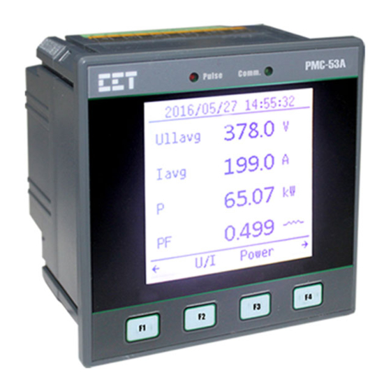
Summary of Contents for CET PMC-53A
- Page 1 PMC-53A Intelligent Multifunction Meter User Manual Version: V1.2A September 12, 2018...
- Page 2 The information contained in this manual is believed to be accurate at the time of publication; however, CET assumes no responsibility for any errors which may appear here and reserves the right to make changes without notice. Please consult CET or your local representative for the latest product specifications.
- Page 3 CET Electric Technology DANGER Failure to observe the following instructions may result in severe injury or death and/or equipment damage. Installation, operation and maintenance of the meter should only be performed by qualified, competent personnel that have the appropriate training and experience with high voltage and current devices.
- Page 4 This warranty is on a return to factory for repair basis. CET does not accept liability for any damage caused by meter malfunctions. CET accepts no responsibility for the suitability of the meter to the application for which it was purchased.
-
Page 5: Table Of Contents
Table of Contents Chapter 1 Introduction ..........................8 1.1 Overview ............................ 8 1.2 Features ............................8 1.3 PMC-53A’ application in Power and Energy Management Systems ......... 11 1.4 Getting more information ......................11 Chapter 2 Installation ..........................12 2.1 Appearance ..........................12 2.2 Unit Dimensions ........................ - Page 6 CET Electric Technology 3.3 Setup Configuration via the Front Panel .................. 28 3.3.1 Making Setup Changes ....................28 3.3.2 Setup Menu ........................30 3.3.3 Configuration ........................ 31 Chapter 4 Applications ........................... 36 4.1 Inputs and Outputs ........................36 4.1.1 Digital Inputs ......................... 36 4.1.2 Digital Outputs ......................
- Page 7 CET Electric Technology 5.5 Demands ..........................56 5.5.1 Present Demands ......................57 5.5.2 Predicted Demands ....................... 57 5.5.3 Peak Demand Log of This Month (Since Last Reset) ............. 57 5.5.4 Peak Demand Log of Last Month (Before Last Reset) ........... 57 5.5.5 Demand Data Structure ....................
-
Page 8: Chapter 1 Introduction
This manual explains how to use the PMC-53A Intelligent Multifunction Meter. Throughout the manual the term “meter” generally refers to all models. This chapter provides an overview of the PMC-53A meter and summarizes many of its key features. 1.1 Overview The PMC-53A Intelligent Multifunction Meter is CET’s latest offer for the low-cost digital power/energy... - Page 9 CET Electric Technology Advanced Measurements 1-Cycle Real-time U & I Waveform Display @ 1s update rate U and I THD, TOHD, TEHD and Individual Harmonics up to 31st Current TDD, TDD Odd, TDD Even, K-Factor and Crest Factor ...
- Page 10 2xDigital Inputs and 2xSold State Pulse Outputs 2xRTD Inputs (PT100 sensor not included) 1xAI and 1xAO (0/4-20mA) System Integration Supported by CET’s PecStar® iEMS and iEEM Modbus RTU for easy integration into 3 -party Energy Management, Automation or SCADA systems ...
-
Page 11: Pmc-53A' Application In Power And Energy Management Systems
CET Electric Technology 1.3 PMC-53A’ application in Power and Energy Management Systems The PMC-53A can be used to monitor 4P3W (Wye), 3P3W (Delta), 1P2W-Uln, 1P2W-Ull or 1P3W connected power system. Modbus communications allow real-time data, DI status and other information to be transmitted across a RS485 network to an Integrated Energy Management system such as PecStar®... -
Page 12: Chapter 2 Installation
Chapter 2 Installation Caution Installation of the PMC-53A should only be performed by qualified, competent personnel that have the appropriate training and experience with high voltage and current devices. The meter must be installed in accordance with all local and national electrical codes. -
Page 13: Unit Dimensions
(14AWG - 22AWG) (5.2 lb-in) Table 2-1 Terminal Dimensions 2.4 Mounting The PMC-53A should be installed in a dry environment with no dust and kept away from heat, radiation and electrical noise source. Installation steps: Remove the installation clips from the meter ... -
Page 14: Wiring Connections
Figure 2-4 Panel Cutout Mounting 2.5 Wiring connections PMC-53A can satisfy almost any three phase power systems. Please read this section carefully before installation and choose the correct wiring method for your power system. The following Wiring Modes are supported: ... -
Page 15: 3-Phase 4-Wire (3P4W) Wye Direct Connection With 3Cts
CET Electric Technology 2.5.1 3-Phase 4-Wire (3P4W) Wye Direct Connection with 3CTs Please consult the serial number label to ensure that the rated system phase voltage is less than or equal to the meter’s rated phase voltage input specification. Set the Wiring Mode to 3P4W. -
Page 16: 3-Phase 4-Wire (3P4W) Wye With 3Pts And 4Cts
CET Electric Technology Figure 2-7 3P4W with 3PTs and 3CTs 2.5.4 3-Phase 4-Wire (3P4W) Wye with 3PTs and 4CTs Please consult the serial number label to ensure that the rated PT secondary voltage is less than or equal to the meter’s rated phase voltage input specification. Set the Wiring Mode to 3P4W. -
Page 17: 3-Phase 3-Wire (3P3W) Direct Delta Connection With 2Cts
CET Electric Technology Figure 2-9 3P3W Direct Connection with 3CTs 2.5.6 3-Phase 3-Wire (3P3W) Direct Delta Connection with 2CTs Please consult the serial number label to ensure that the rated system line voltage is less than or equal to the meter’s rated line voltage input specification. Set the Wiring Mode to 3P3W. -
Page 18: 3-Phase 3-Wire (3P3W) Delta With 2Pts And 2Cts
CET Electric Technology Figure 2-11 3P3W Delta with 2PTs and 3CTs 2.5.8 3-Phase 3-Wire (3P3W) Delta with 2PTs and 2CTs Please consult the Serial Number Label to ensure that the voltage is less than or rated PT secondary equal to the meter’s rated phase voltage input specification. -
Page 19: 1-Phase 2-Wire, Uln (1P2W-Uln) Direct Connection With 1Ct
CET Electric Technology Figure 2-13 1P3W Direct Connection with 2CTs 2.5.10 1-Phase 2-Wire, Uln (1P2W-Uln) Direct Connection with 1CT Please consult the Serial Number Label to ensure that the rated system phase voltage is less than or equal to the meter’s rated phase voltage input specification. Set the Wiring Mode to 1P2W, L-N. -
Page 20: Communications Wiring
The following figure illustrates the RS485 communications connections on the PMC-53A: Figure 2-14 Communications Connections The PMC-53A provides one standard RS485 port and one optional RS485. Up to 32 devices can be connected on a RS485 bus. The overall length of the RS485 cable connecting all devices should not exceed 1200m. -
Page 21: Pulse Output Wiring
Figure 2-17 DO Connections 2.9 Pulse Output Wiring The following figure illustrates the Pulse Output connections on the PMC-53A when the DO Control Mode setup register is programmed for Energy Pulsing: Figure 2-18 Pulse Output (Solid State Relay) Connections for Energy Pulsing... -
Page 22: Rtd Input Wiring
CET Electric Technology Figure 2-21 AO Connections 2.12 RTD Input Wiring The following figure illustrates the RTD Input connections on the PMC-53A: Figure 2-22 RTD Input Connections 2.13 Power Supply Wiring For AC supply, connect the live wire to the L/+ terminal and the neutral wire to the N/- terminal. -
Page 23: Chapter 3 Front Panel
CET Electric Technology Chapter 3 Front Panel The PMC-53A has a large, easy to read Dot-Matrix LCD display with backlight and four buttons for data display and meter configuration. This chapter introduces the front panel operations. Figure 3-1 Front Panel 3.1 Using the Front Panel Buttons... -
Page 24: Data Display
CET Electric Technology 3.2 Data Display Figure 3-2 Data Display Menu Throughout this document, the phase-to-neutral notations of A/B/C and L1/L2/L3 as well as the phase- to-phase notations of AB/BC/CA and L12/L23/L31 may be used interchangeably for specifying a certain parameter to be a phase-to-neutral or phase-to-phase value, respectively. -
Page 25: Power
CET Electric Technology Notes: The I4 parameter only appears if the meter is equipped with the corresponding I4 option. The Ir parameter only shows a valid value when the Wiring Mode is set to 3P3W or 3P4W; otherwise, it shows “0”. -
Page 26: Max./Min
CET Electric Technology Display 6 (Unbalance) Current Voltage Display 7 (U Sequence)* Display 8 (I Sequence)* Display 1 U1/U12 Harmonic Spectrum (Odd) Display 2 U2/U23 Harmonic Spectrum (Odd) Display 3 U3/U31 Harmonic Spectrum (Odd) <Graph> Display 4 I1 Harmonic Spectrum (Odd) -
Page 27: Tou
CET Electric Technology Display 3 Timestamp Timestamp Timestamp Display 4 Timestamp Timestamp Timestamp Timestamp L1 U THD L2 U THD L3 U THD Display 1 Timestamp Timestamp Timestamp L1 I THD L2 I THD L3 I THD Display 2 Timestamp... -
Page 28: I/O
3.2.9 SOE The PMC-53A with Firmware V1.00.03 or later supports the display of the SOE Log with up to 100 Events (2 Events per page) such as I/O Changes, Setpoint, …etc, on the Front Panel. In addition, the SOE Log can be reset from the Front Panel. - Page 29 CET Electric Technology When the password has been entered, pressing <F4>/<OK> will advance to the setup menu if the password is correct. 2) Selecting a parameter to change: Press <F2>/<↑> or <F3>/<↓> to scroll to the desired sub-menu or parameter.
-
Page 30: Setup Menu
CET Electric Technology 3.3.2 Setup Menu Figure 3-3 Setup Menu... -
Page 31: Configuration
CET Electric Technology 3.3.3 Configuration The Setup Configuration mode provides access to the following setup parameters: Label Description Range Default Menu Password Enter Password 0000 to 9999 0000 Basic DEMO/ Wiring Mode Meter’s Wiring Connection 1P2W L-N/1P2W L-L/ 3P4W 1P3W/3P3W/3P4W... - Page 32 CET Electric Technology Group #9 0=Disabled, 1=Over Setpoint Type Setpoint Type 2=Under Setpoint Parameter Setpoint Source See Table 3-11 None OvLim Over Limit UnLim Under Limit ActiveDelay Active Delay 0 to 9999s InactiveDelay Inactive Delay 0 to 9999s Trigger1 Setpoint Trigger1...
- Page 33 CET Electric Technology Language System Language Chinese/English English Delimiter Delimiter Option1/Option2 Option1 Main 1st* Default Display 1 parameter Ullavg Main 2nd* Default Display 2 parameter Iavg See Note 8) Main 3rd* Default Display 3 parameter P (kW Total) Main 4th*...
- Page 34 CET Electric Technology Setpoint Parameter Scale Unit None Uln (Any Phase Voltage) Ull (Any Line Voltage) I (Any Phase Current) In (Calculated) Frequency P (kW Total) Q (kvar Total) S (kVA Total) PF (PF Total) P DMD (kW Total Present Demand)
- Page 35 CET Electric Technology 7) The Delimiter setup register supports two options, 1 and 2: Option 1: “,” is used as the x1000 delimiter and “.” as the decimal point (e.g. 123,456,789.0). Option 2: “ ” is used as the x1000 delimiter and “,” as the decimal point (e.g. 123 456 789,0).
-
Page 36: Chapter 4 Applications
4.1 Inputs and Outputs 4.1.1 Digital Inputs The PMC-53A comes optionally with four or six self-excited Digital Inputs that are internally wetted at 24 VDC with a sampling frequency of 1000Hz and programmable debounce. The PMC-53A provides the following programmable functions for its digital inputs:... -
Page 37: Energy Pulse Outputs
Please refer to Section 4.4 for a detailed description. Since there are multiple ways to trigger the Digital Outputs on the PMC-53A, a prioritized scheme has been developed to avoid conflicts between different applications. In general, Front Panel Control has the highest priority and can override other control schemes. -
Page 38: Rtd Input
The 2-wire outputs of the PT100 sensor are connected to the RTD Input of the PMC-53A if so equipped. The PMC-53A can provide accurate temperature monitoring with the optional RTD inputs for measuring the temperature of the Neutral Conductor, Transformer or other equipment. -
Page 39: Energy Measurements
Demand is defined as the average power consumption over a fixed interval (usually 15 minutes) based on the sliding window method. The PMC-53A provides Present Demand and Predicted Demand for Ia, Ib, Ic, kW Total, kvar Total and kVA Total as well as kW Total, kvar Total and kVA Total of TOU Tariff 1 to 8. -
Page 40: Power Quality
The PMC-53A provides the following PQ parameters: 4.3.2.1 Harmonics The PMC-53A provides harmonic analysis for THD, TOHD, TEHD and individual harmonics up to the 31 order. All harmonic parameters are available on the Front Panel and through communications. In addition, the PMC-53A also provides TDD, K-factor and Crest-factor measurements for Current. -
Page 41: Unbalance
Harmonics … Harmonics Harmonics Harmonics Table 4-5 Harmonic Measurements 4.3.3 Unbalance The PMC-53A provides Voltage and Current Unbalance measurements. The calculation method of Voltage and Current Unbalances are listed below: 100% 100% Voltage Unbalance = Current Unbalance = where V1, V2 are the Positive and Negative Sequence Components for Voltage, respectively. -
Page 42: Setpoints
CET Electric Technology 4.4 Setpoints The PMC-53A comes standard with 9 user programmable Setpoints which provide extensive control by allowing a user to initiate an action in response to a specific condition. Typical setpoint applications include alarming, fault detection and power quality monitoring. - Page 43 CET Electric Technology Setup Parameter Definition Options/Default* 0=Over Setpoint* Setpoint Type Over or Under Setpoint. 1=Under Setpoint Setpoint Specify the parameter to be monitored. See Table 4-7 Parameter Specify the value that the setpoint parameter must exceed Over Limit for Over Setpoint to become active or for Under Setpoint to become inactive.
-
Page 44: Logging
4.5 Logging 4.5.1 Max./Min. Log The PMC-53A records the Max. Log and Min. Log of This Month (Since Last Reset) and Last Month (Before Last Reset) with timestamp for 45 parameters. Each log includes the relevant parameter value and its timestamp. The recorded data is stored in non-volatile memory and will not suffer any loss in the event of a power failure. -
Page 45: Monthly Energy Log
Table 4-10 Peak Demand Log 4.5.3 Monthly Energy Log The PMC-53A stores monthly energy data for the present month and the last 12 months. The Monthly Energy Log Self-read Time setup parameter allows the user to specify the time and day of the month for the Recorder’s Self-read operation via communications. -
Page 46: Soe Log
4.5.5 SOE Log The PMC-53A’s SOE Log can store up to 100 events such as Power-on, Power-off, Digital Input status changes, Digital Output status changes, Setup changes and Setpoint events in its non-volatile memory. Each event record includes the event classification, its relevant parameter values and a timestamp in ±1 ms resolution. -
Page 47: Time Of Use (Tou)
TOU is used for electricity pricing that varies depending on the time of day, day of week, and season. The TOU system allows the user to configure an electricity price schedule inside the PMC-53A and accumulate energy consumption into different TOU tariffs based on the time of consumption. TOU programming is only supported through communications. -
Page 48: Diagnostics
TOU data is available through the front panel and communications. 4.7 Diagnostics The PMC-53A provides wiring error detection for 3P4W and 3P3W wiring modes, which allow users to check for possible problems especially during the initial commissioning stage. The following wiring errors may be detected: ... -
Page 49: Chapter 5 Modbus Register Map
This chapter provides a complete description of the Modbus register map (Protocol Version 1.4) for the PMC-53A to facilitate the development of 3 party communications driver for accessing information on the PMC-53A. For a complete Modbus Protocol Specification, please visit http://www.modbus.org. The PMC-53A supports the following Modbus functions: 1) Read Holding Registers (Function Code 0x03) - Page 50 CET Electric Technology 0076 Displacement PFb Float 0078 Displacement PFc Float 0080 Displacement PF Total Float 0082 Scaled Float 0084 Reserved Float 0086 RTD 1 Float ︒C 0088 RTD 2 Float 0090 Float 0092 Reserved Float 0094 Reserved Float 0096...
-
Page 51: Energy Measurements
8) The PMC-53A has one SOE Log and five DR Logs. Each of these logs has a Log Pointer that indicates its current logging position. The range of the Log Pointer is between 0 and 0xFFFFFFFF, and it is incremented by one for every new log generated and will roll over to 0 if its current value is 0xFFFFFFFF. -
Page 52: Phase A (L1) Energy Measurements
CET Electric Technology 0504 kWh Net INT32 0506 kWh Total INT32 0508 kvarh Import INT32 0510 kvarh Export INT32 kvarh 0512 kvarh Net INT32 0514 kvarh Total INT32 0516 kVAh INT32 kVAh 0518 kvarh Q1 INT32 0520 kvarh Q2 INT32... -
Page 53: Phase B (L2) Energy Measurements
CET Electric Technology 0640 kvarh Q2 INT32 0642 kvarh Q3 INT32 0644 kvarh Q4 INT32 0646 kWh Import of T1 INT32 kvarh 0648 kWh Export of T1 INT32 0650 kvarh Import of T1 INT32 0652 kvarh Export of T1 INT32... -
Page 54: Phase C (L3) Energy Measurements
CET Electric Technology 0776 kWh Import of T2 INT32 0778 kWh Export of T2 INT32 0780 kvarh Import of T2 INT32 kvarh 0782 kvarh Export of T2 INT32 0784 kVAh of T2 INT32 kVAh 0786 kWh Import of T3 INT32... -
Page 55: Interval Energy Measurements
CET Electric Technology 0912 kvarh Export of T3 INT32 0914 kVAh of T3 INT32 kVAh 0916 kWh Import of T4 INT32 0918 kWh Export of T4 INT32 0920 kvarh Import of T4 INT32 kvarh 0922 kvarh Export of T4 INT32... -
Page 56: Current Harmonic Measurements
CET Electric Technology 1316 Ic TDD Even Float 1318 Ia K-factor Float 1320 Ib K-factor Float 1322 Ic K-factor Float 1324 Ia Crest-factor Float 1326 Ib Crest-factor Float 1328 Ic Crest-factor Float 1330 Voltage Unbalance Float 1332 Current Unbalance Float Table 5-10 Power Quality Measurements 5.4.2 Current Harmonic Measurements... -
Page 57: Present Demands
CET Electric Technology 5.5.1 Present Demands Register Property Description Format Scale Unit 3000 Float 3002 Float 3004 Float 3006 kW Total Float 3008 kvar Total Float 3010 kVA Total Float Table 5-13 Present Demand Measurements 5.5.2 Predicted Demands Register Property... -
Page 58: Demand Data Structure
CET Electric Technology 3630~3635 kVA Total 3636~3641 kW Total of T1 3642~3647 kvar Total of T1 3648~3653 kVA Total of T1 3654~3659 kW Total of T2 3660~3665 kvar Total of T2 3666~3671 kVA Total of T2 3672~3677 kW Total of T3... -
Page 59: Min. Log Of This Month (Since Last Reset)
CET Electric Technology 4120~4125 kVAa 4126~4131 kVAb 4132~4137 kVAc 4138~4143 kVA Total 4144~4149 4150~4155 4156~4161 4162~4167 PF Total 4168~4173 Frequency 4174~4179 In (Calculated) 4180~4185 Uan/Uab THD 4186~4191 Ubn/Ubc THD 4192~4197 Ucn/Uca THD 4198~4203 Ia THD 4204~4209 Ib THD 4210~4215 Ic THD... -
Page 60: Max. Log Of Last Month (Before Last Reset)
CET Electric Technology 4504~4509 Ib THD 4510~4515 Ic THD 4516~4521 Ia K-factor 4522~4527 Ib K-factor 4528~4533 Ic K-factor 4534~4539 Ia Crest-factor 4540~4545 Ib Crest-factor 4546~4551 Ic Crest-factor 4552~4557 Voltage Unbalance 4558~4563 Current Unbalance 4564~4569 4570~4575 Ir* (Residual Current) Available in Firmware V1.00.06 or later Table 5-19 Min. -
Page 61: Min. Log Of Last Month (Before Last Reset)
CET Electric Technology 5.6.4 Min. Log of Last Month (Before Last Reset) Register Property Description Format Scale Unit 4900~4905 4906~4911 4912~4917 4918~4923 Uln Average 4924~4929 4930~4935 4936~4941 4942~4947 Ull Average 4948~4953 4954~4959 4960~4965 4966~4971 I Average 4972~4977 4978~4983 4984~4989 4990~4995... -
Page 62: Monthly Energy Log
CET Electric Technology 5.7 Monthly Energy Log Register Property Description Format Scale Unit 0980 Month INT16 0* to 12 High-order Byte: Year (0-99) 0981 INT16 Low-order Byte: Month (1-12) Time Stamp High-order Byte: Day (1-31) 0982 INT16 (20YY/MM/DD Low-order Byte: Hour (0-23) -
Page 63: Daily And Monthly Freeze Logs (Optional)
This register represents the Month when it is read. To read the Monthly Energy Log, this register must be first written to indicate to the PMC-53A which log to load from memory. The range of this register is from 0 to 12, which represents the Present Month and the Last 12 Months. For example, if the current month is 2016/10, “0”... -
Page 64: Soe Log
CET Electric Technology Hour High Minute Second Millisecond +4~+5 Peak Demand Value Table 5-26 Demand Data Structure Notes: There is no Log Pointer that indicates the current logging position. Writing a value N between 1 and 36 to the Index register to retrieve the Monthly Freeze Log of the N entry. - Page 65 CET Electric Technology SOE Classification Event Sub- Status Event Value Description Classification Classification 1 / 0 DI1 Inactive / DI1 Active 1 / 0 DI2 Inactive / DI2 Active 1 / 0 DI3 Inactive / DI3 Active 1=DI Changes 1 / 0...
- Page 66 CET Electric Technology Over Current Unbalance Setpoint 1 / 0 Active/Return 1 / 0 Reversal Phase Setpoint Active/Return 1 / 0 Over I4 Setpoint Active/Return 1 / 0 Over AI Setpoint Active/Return Reserved Over Temprature1 Setpoint 1 / 0 Active/Return...
- Page 67 CET Electric Technology Under U0 (Zero Sequence) Setpoint* 1 / 0 Active/Return System Parameter Fault 4=Self- Internal Parameter Fault diagnosis TOU Parameter Fault Memory Fault Power On Power Off Clear Present Energy via Front Panel Clear Historical Monthly Energy Log via...
-
Page 68: Data Recorder Log (Optional)
CET Electric Technology 2) Clear Historical Monthly Energy Log means to clear the Monthly Energy Log of the last 1 to 12 months, excluding the Monthly Energy Log for the Present Month. 3) Clear All Data via Front Panel or Communication means to clear 3-Phase Total Energy registers, Phase A/B/C Energy registers, Monthly Energy Log of the Present Month, All Peak Demands, All Max./Min. - Page 69 CET Electric Technology 2=1P2W L-L, 3=1P3W 4=3P3W, 5=3P4W* 6021 PF Convention UINT16 0=IEC*, 1=IEEE, 2=-IEEE 6022 kVA Calculation UINT16 0=Vector*, 1=Scalar 6023 Ia Polarity UINT16 6024 Ib Polarity UINT16 0=Normal*, 1=Reverse 6025 Ic Polarity UINT16 6026~6027 Reserved UINT16 6028 THD Calculation...
-
Page 70: I/O Setup
CET Electric Technology The Self-Read Time applies to both the Peak Demand Log as well as the Max./Min. Log and supports the following three options: A zero value means that the Self-Read will take place at 00:00 of the first day of each month. - Page 71 CET Electric Technology 6209 DI2 Debounce UINT16 6210 DI3 Debounce UINT16 6211 DI4 Debounce UINT16 6212 DI5 Debounce UINT16 6213 DI6 Debounce UINT16 6214~6215 Reserved 6216 DI1 Pulse Weight UINT32 6218 DI2 Pulse Weight UINT32 6220 DI3 Pulse Weight UINT32...
-
Page 72: Communication Setup Parameters
UINT16 0 to 4 6589 Trigger Action 2 UINT16 Table 5-38 Setpoint Setup Parameters Notes: 1) The PMC-53A provides the following setpoint parameters: Setpoint Parameter Scale Unit None Uln (Any Phase Voltage) Ull (Any Line Voltage) I (Any Phase Current) -
Page 73: Data Recorder Setup
4) Only when DOx Mode is set to Remote Control/Setpoint, setting Setpoint Triggers to DOx Closed is valid. In addition, Only when the PMC-53A’s Basic Function option is “3” (4xDI+3xRelay Output) or “A” (4xDI+2xSS Pulse Output) would setting the Setpoint Trigger to DO1 Closed or DO2 Closed have meaning. -
Page 74: Tou Setup
CET Electric Technology 0=Stop-when-Full Recording Mode UINT16 1=First-In-First-Out Recording Depth UINT16 0 to 10,000 Recording Interval UINT32 60 to 3456000s Offset Time UINT16 0 to 43200s Number of Parameters UINT16 0 to 16 Parameter #1 UINT16 Please refer to Appendices... -
Page 75: Season
CET Electric Technology 5.12.2 Season The PMC-53A has two sets of Season setup parameters, one for each TOU. The Base Addresses for the two sets are 7100 and 8100, respectively, where the Register Address = Base Address + Offset. For example, the register address for TOU #1’s Season #2’s Start Date is 7100+4 = 7104. -
Page 76: Daily Profile
CET Electric Technology 5.12.3 Daily Profile The PMC-53A has two sets of Daily Profile setup parameters, one for each TOU. Register Property Description Format 7200~7223 Daily Profile #1 7224~7247 Daily Profile #2 7248~7271 Daily Profile #3 7272~7295 Daily Profile #4... -
Page 77: Alternate Days
Alternate Day, its assigned Daily Profile will override the “normal” Daily Profile for this day according the TOU settings. The PMC-53A has two sets of Alternate Days setup parameters, one for each TOU. The Base Addresses for the two sets are 7700 and 8700, respectively, where the Register Address = Base Address + Offset. -
Page 78: Time
5.13 Time There are two sets of Time registers supported by the PMC-53A – Year / Month / Day / Hour / Minute / Second (Registers # 60000 to 60002) and UNIX Time (Register # 60004). When sending time to the PMC- 53A over Modbus communications, care should be taken to only write one of the two Time register sets. -
Page 79: Clear/Reset Control
CET Electric Technology if this function is enabled through the Arm Before Execute Enable Setup register (6032), which is disabled by default. Before executing an OPEN or CLOSE command on a Digital Output, it must be “Armed” first. This is achieved by writing the value 0xFF00 to the appropriate register to “Arm” a particular DO operation. -
Page 80: Meter Information
CET Electric Technology 2) Writing 0xFF00 to the Clear All Energy Registers register to clear the 3-Ø Total and Per-Phase energy registers. 3) Writing 0xFF00 to the Clear Present Monthly Energy Log register to clear the Monthly Energy Log of the Present Month. - Page 81 * Available in Firmware V1.00.04 or later Table 5-54 Meter Information Notes: 1) The Meter Model appears from registers 60200 to 60219 and contains the ASCII encoding of the string “PMC-53A” as shown in the following table. Register Value(Hex) ASCII...
-
Page 82: Appendix A Data Recorder Parameter List
CET Electric Technology Appendix A Data Recorder Parameter List Description Description Description Real-time Measurements None PF Total Frequency kW Total Uan/Uab Angle kvara Ubn/Ubc Angle Uln Average kvarb Ucn/Uca Angle kvarc Ia Angle kvar Total Ib Angle kVAa Ic Angle... -
Page 83: Appendix B Data Recorder Default Settings
CET Electric Technology Appendix B Data Recorder Default Settings Parameter DR 1 DR 2 DR 3 DR 4 DR 5 Triggered by Triggered by Triggered by Triggered by Triggered by Trigger Mode Timer Timer Timer Timer Timer Recording 5760 5760... -
Page 84: Appendix C Bacnet Mstp Implementation
Appendix C BACNet MSTP Implementation 1) Basic Information The PMC-53A with the Firmware V1.00.03 or later supports the BACnet MS/TP protocol and can easily be connected to a BACnet MS/TP network using an off-the shelf BACnet router. The PMC- 53A provides four types of BACnet objects. Standard Protocol Implementation Conformance Statement (PICS) as illustrated in table below describes the required characteristics of the BACnet implementation. - Page 85 Use the Present_Value property of the Analog_Input objects for all read-only numeric variables in PMC-53A. These objects support the Description and Reliability optional properties and all required Analog_Input object properties. None of them are writable. The values that are not instantaneous (i.e.
- Page 86 CET Electric Technology AI 0042 kVAb AI 0044 kVAc AI 0046 kVA Total AI 0048 AI 0050 0 to 1 AI 0052 AI 0054 PF Total AI 0056 Frequency Neutral Current (Calculated) AI 0070 I4 (Optional Measurement) AI 0072 AI 0082 RTD1 ℃...
- Page 87 Values are checked when written, and errors are returned for invalid entries. The table below describes how the Setup Registers of the PMC-53A are represented in BACnet, their valid ranges, their defaults as well as how they are used. PMC-53A supports the Description, Relinquish_Default and Priority_Array optional properties.
- Page 88 DO 4 0 = Inactive, 1 = Active 7) Additional Front Panel Setup Parameters for BACnet MS/TP The following BACnet MS/TP setup parameters should be configured via the PMC-53A’s Front Panel before connecting the PMC-53A to a BACnet MS/TP network. Parameters...
-
Page 89: Appendix D N2 Implementation
ADF points. The Command Register with override capability is used to reset groups of parameters held in the device. Before integrating the PMC-53A into a Metasys N2 Network, please make sure that all N2 devices are configured, started and running properly. No more than 32 N2 devices should be connected to an NCM’s N2 Bus segment, and no more than 100 N2 devices when repeaters are used. - Page 90 CET Electric Technology dPFc Uan Angle PF Total Ubn Angle Frequency Ucn Angle Neutral Current Ia Angle ° (Calculated) I4 (Optional Ib Angle Measurement) kWh Import Ic Angle kWh Export Operating Time kWh Total Interval kWh Import kWh Net Interval kWh Export...
-
Page 91: Appendix E Dnp Profile
CET Electric Technology Appendix E DNP Profile This section contains the DNP Device Profile Information according to the standard format defined in the DNP 3.0 Subset Definitions Document and should provide a complete application configuration guide. DNP V3.0 Vendor Name:... - Page 92 CET Electric Technology DNP V3.0 Reports Binary Input Change Events when no specific Reports time-tagged Binary Input Change Events when no variation requested: specific variation requested: Never Never Only time-tagged Binary Input Change with Time ...
- Page 93 Unsolicited Response Data Link Layer The PMC-53A can be assigned a device address between 0 and 65519. After device restart, Function Code 0 (Reset of Remote Link) must be executed to enable DNP communication. The following table describes which Data Link Layer functions are supported.
- Page 94 CET Electric Technology DNP Point Map Object 1 - Binary Input Status with Flags (Included in Class 0 responses) Read with Object 1, Variation 2, and Qualifier 6. Point Description Format Range UINT8 Bit Flags UINT8 Bit Flags UINT8 Bit Flags...
- Page 95 CET Electric Technology CTc polarity may be reversed (3P4W only) Supported Flags: Bit 0 (ONLINE): 0 = Offline, which represents that the control of the Output could not be implemented. 1 = Online, which represents that the Output works properly, once control request has been sent, the command could be correctly implemented.
- Page 96 CET Electric Technology DI5 Pulse Counter UINT32 DI6 Pulse Counter UINT32 Notes: If the Device Model does not support DI, all DI Pulse Counters would be set to “0”. If 4xDIs are supported on the Device Model, DI5 and DI6 Pulse Counter would be set to “0”.
- Page 97 CET Electric Technology Ubn/Ubc (3P3W) Angle INT32 Ucn/Uca (3P3W) Angle INT32 Ia Angle INT32 Ib Angle INT32 Ic Angle INT32 In (Calculated) INT32 INT32 x1000 INT32 Displacement PFa INT32 Displacement PFb INT32 x1000 Displacement PFc INT32 Displacement PF Total INT32...
- Page 98 CET Electric Technology ∑kW Peak Demand of Last Month (Before Last Reset) INT32 ∑kvar Peak Demand of Last Month (Before Last Reset) INT32 ∑kVA Peak Demand of Last Month (Before Last Reset) INT32 Notes: When the Wiring Mode is 1P2W L-N or 1P2W L-L, the L2 and L3 phase voltages and currents have no meaning, and their registers are reserved.
-
Page 99: Appendix F Technical Specifications
CET Electric Technology Appendix F Technical Specifications Voltage Inputs (V1, V2, V3, VN) Standard Un 400VLN/690VLL Range 10V to 1.2Un Overload 1.2xUn continuous, 2xUn for 1s Burden <0.02VA per phase Measurement Category CAT III up to 600VLL Frequency 45-65Hz Current Inputs (I11, I12, I21, I22, I31, I32) Standard In=5A/1A Auto-scale Class 0.5S for 5A and Class 1 for 1A... - Page 100 CET Electric Technology Accuracy Parameters Accuracy Resolution Voltage ±0.2% Reading + 0.05% F.S. 0.001V Current ±0.2% Reading + 0.05% F.S. 0.001A I4 (measurement) ±0.2% 0.001A kW, kvar, kVA ±0.5% Reading + 0.05% F.S. 0.001k kWh, kVAh IEC 62053-22 Class 0.5S 0.1kXh...
-
Page 101: Appendix G Standards Compliance
CET Electric Technology Appendix G Standards Compliance Safety Requirements CE LVD 2014 / 35 / EU EN61010-1: 2010 EN61010-2-030: 2010 cTUVus for UL/CSA Certification UL 61010-1: 2012 UL 61010-2-030: 2012 CAN/CSA-C22.2 No.61010-1: 2012 CSA C22.2 No. 61010-2-030-12 Electrical safety in low voltage distribution... -
Page 102: Appendix H Ordering Guide
CET Electric Technology Appendix H Ordering Guide... -
Page 103: Contact Us
CET Electric Technology Contact us CET Inc. 8/F, Westside, Building 201, Terra Industrial & Tradepark, Che Gong Miao, Shenzhen, Guangdong, P.R.China 518040 Tel: +86.755.8341.5187 Fax: +86.755.8341.0291 Email: sales@cet-global.com Web: www.cet-global.com...
Need help?
Do you have a question about the PMC-53A and is the answer not in the manual?
Questions and answers