
Related Manuals for AXIOMTEK AX92352


Summary of Contents for AXIOMTEK AX92352
- Page 1 AX92352 2-CH Encoder Card with Real-time Trigger I/O AX92353 4-CH Lighting Control Module User’s Manual...
- Page 2 Disclaimers This manual has been carefully checked and believed to contain accurate information. Axiomtek Co., Ltd. assumes no responsibility for any infringements of patents or rights of any third party, or any liability arising from such use. Axiomtek does not warrant or assume any legal liability or responsibility for the accuracy, completeness or usefulness of any information in this document.
-
Page 3: Esd Precautions
When handling boards and components, wear a grounding wrist strap available from most electronic component stores. Trademarks Acknowledgments Axiomtek is a trademark of Axiomtek Co., Ltd. ® Windows is a trademark of Microsoft Corporation. IBM, PC/AT, PS/2, VGA are trademarks of International Business Machines Corporation. -
Page 4: Table Of Contents
Isolated Trigger Output ................13 3.1.5 Isolated Encoder Input ................13 3.1.6 LED Lighting Control (AX92353) ............... 14 Section 4 Operating ........... 15 Operating of AX92352 ............... 15 4.1.1 Encoder function ..................15 4.1.2 De-bounce filter ..................16 4.1.3 Encoder Homing..................17 4.1.4... - Page 5 Application ..................21 4.3.1 Scenario 1 ....................21 4.3.2 Scenario 2 ....................21 APPENDIX A HARDWARE INSTALLATION ....23...
-
Page 7: Section 1 Introduction
DIO that can be used with other devices for your vision cases. The AX92352 vision I/O card can fit in the PCI Express slot of any vision control system. It can also be used with an optional add-on module AX92353, which provides LED output support to meet further application needs. -
Page 8: Specifications (Ax92352)
AX92352/AX92353 2-CH Encoder Card with Real-time Trigger I/O Specifications (AX92352) Isolated encoder input Number of channels: 2 Support mode: incremental quadrature encoder input (A/B/Z phase, x1/4 x1/3 x1/2 x1 x2 x4 mode) Type of wiring: differential or single-ended 5V, 12V open collector ... - Page 9 AX92352/AX92353 2-CH Encoder Card with Real-time Trigger I/O Configuration: Derived from 4CH trigger input or encoder input. The user can set the pulse delay time and duration time. Trigger sources: 4CH trigger input/ encoder: 4x Linear function, 2x FIFO (Each channel supports two sources.)
-
Page 10: Specifications (Ax92353)
AX92352/AX92353 2-CH Encoder Card with Real-time Trigger I/O Specifications (AX92353) Note: This optional add-on module cannot be operating independently and must be used in conjunction with the AX92352. LED lighting control module Number of channels: 4 Constant current control ... -
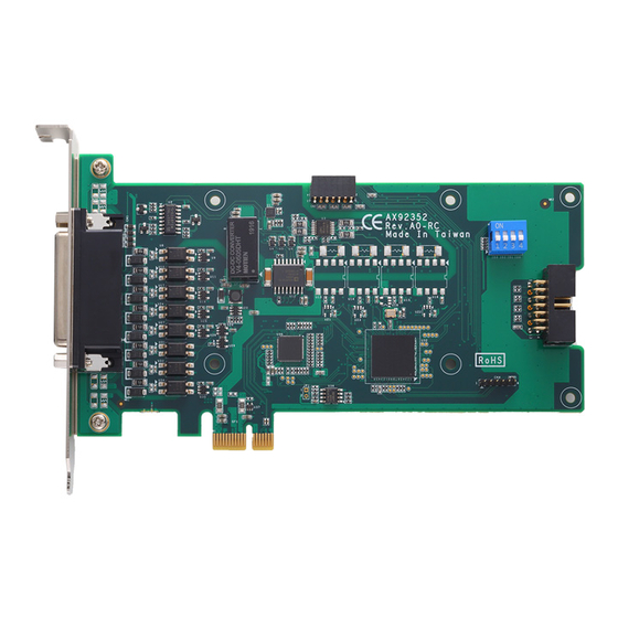
Page 11: Dimensions
AX92352/AX92353 2-CH Encoder Card with Real-time Trigger I/O Dimensions AX92352 Component Side AX92353 Component Side Introduction... - Page 12 AX92352/AX92353 2-CH Encoder Card with Real-time Trigger I/O This page is intentionally left blank. Introduction...
-
Page 13: Section 2 Connectors
AX92352/AX92353 2-CH Encoder Card with Real-time Trigger I/O Section 2 Connectors Connectors Connectors connect the board with other parts of the system. Loose or improper connection might cause malfunctions. Make sure all connectors are properly and firmly connected. The following table lists the function of each connector on the cards. -
Page 14: Communication Connector (Cn3)
AX92352/AX92353 2-CH Encoder Card with Real-time Trigger I/O 2.1.2 Communication Connector (CN3) The communication connector allows the user to synchronize AX92352 and AX92353 via the communication cable to control LED functions. 2.1.3 Board ID (SW1) Default board ID setting is 0 (0x0000) -
Page 15: 8-Pin Terminal Connector For Led Lighting Control (Cn2)
AX92352/AX92353 2-CH Encoder Card with Real-time Trigger I/O 2.1.5 8-Pin Terminal Connector for LED Lighting Control (CN2) Description Description LED1 - LED1 + LED2 - LED2 + LED3 - LED3 + LED4 - LED4 + 2.1.6 Communication Connector (CN3) When using the AX92353, please plug the communication cable into this connector to link to AX92352. - Page 16 AX92352/AX92353 2-CH Encoder Card with Real-time Trigger I/O This page is intentionally left blank Connectors...
-
Page 17: Section 3 I/O Connection
Section 3 I/O Connection I/O Connection Refer to this section to connect any cables between the cards and the device. Each of the following I/O figures illustrates their respective connection on the AX92352 and AX92353. 3.1.1 Isolated Digital Input The figure shows how to connect between external input source and the AX92352. -
Page 18: Isolated Digital Output
3.1.2 Isolated Digital Output The figure shows how to connect between an output channel and the AX92352. If an external voltage 5~30 VDC is applied to an isolated output channel, the current will flow from the external voltage source to the system. -
Page 19: Isolated Trigger Output
AX92352/AX92353 2-CH Encoder Card with Real-time Trigger I/O 3.1.4 Isolated Trigger Output The figure shows how to connect between an output channel and the system. If an external voltage 5~30 VDC is applied to an isolated output channel, the current will flow from the external voltage source to the system. -
Page 20: Led Lighting Control (Ax92353)
AX92352/AX92353 2-CH Encoder Card with Real-time Trigger I/O Open Collector Type: 3.1.6 LED Lighting Control (AX92353) The figure shows how to connect between lighting output channel and LED. LED1- LED1+ LED4- LED4+ I/O Connection... -
Page 21: Section 4 Operating
Phase Z is used by the AX92352 to locate a position of the motor when the quadrature encoder completes a 360° rotation, so that the counter value of Phase Z can reset to zero if the configuration sets the homing conditions. -
Page 22: Bounce Filter
AX92352/AX92353 2-CH Encoder Card with Real-time Trigger I/O The figure below depicts a case where a valid encoder value is pulse edge from phase A encoder signal. The 1/2, 1/3 or 1/4 mode defines the number of pulses to skip between valid acquisition. -
Page 23: Encoder Homing
AX92352/AX92353 2-CH Encoder Card with Real-time Trigger I/O 4.1.3 Encoder Homing This function can clear the counter value when Phase Z has a rising edge or when the user gives the command. Further, the user can configure a specific value by software. -
Page 24: Trigger Input/ Output
The user can select any of the following items as a triggering condition that prompts the AX92352 to generate a trigger output: Trigger Input CH 0~3, Encoder 0_Linear 0, Encoder 0_Linear 1, Encoder 0_FIFO, Encoder 1_Linear 0, Encoder 1_Linear 1, Encoder 1_FIFO Note: One trigger source can be set to activate multiple trigger outputs. -
Page 25: Interrupt
Interrupt This function can send an interrupt signal to the host PC. The user can select two conditions for the AX92352 to generate an interrupt signal. Operating of AX92353 This section shows the operations of the AX92353 4-CH LED lighting control module. This module provides strobe and trigger operating modes suitable for various machine vision applications. - Page 26 AX92352/AX92353 2-CH Encoder Card with Real-time Trigger I/O Trigger Source Lighting Control Delay Time Duration (LED ON) Invert The condition of trigger source can be set as rising trigger or falling trigger. Trigger Source Lighting Control Delay Time Rising Trigger...
- Page 27 Scenario 2 In this application, the system needs to record the encoder positions for camera trigger. The AX92352’s hardware is specifically designed to store encoder positions. When the sensor produces an external latch input signal, the encoder position value will be recorded to the latch register.
- Page 28 AX92352/AX92353 2-CH Encoder Card with Real-time Trigger I/O This page is intentionally left blank Operating...
- Page 29 AX92352/AX92353 2-CH Encoder Card with Real-time Trigger I/O APPENDIX A HARDWARE INSTALLATION This section will show you how to connect the AX92352 to the optional module AX92353 using the communication cable. Installation Procedure: Step 1 Align the AX92352 and AX92353 with the slots, and then press the AX92352 into the slot.
Need help?
Do you have a question about the AX92352 and is the answer not in the manual?
Questions and answers