Table of Contents
Advertisement
Quick Links
Advertisement
Table of Contents

Related Manuals for AXIOMTEK AIE900A-AO Series


Summary of Contents for AXIOMTEK AIE900A-AO Series
- Page 1 AIE900A-AO Series Edge AI Embedded System User’s Manual...
-
Page 2: Disclaimers
Axiomtek does not make any commitment to update any information in this manual. Axiomtek reserves the right to change or revise this document and/or product at any time without notice. No part of this document may be reproduced, stored in a retrieval system, or transmitted in any forms or by any means, electronic, mechanical, photocopying, recording, among others, without prior written permissions of Axiomtek Co., Ltd. -
Page 3: Safety Precautions
Safety Precautions Before getting started, please read the following important safety precautions. The AIE900A-AO does not come with an operating system which must be loaded first before installation of any software into the computer. Be sure to ground yourself to prevent static charge when installing any internal components. -
Page 4: Classification
Classification Degree of production against electric shock: not classified Degree of protection against ingress of water: IP40 Equipment not suitable for use in the presence of a flammable anesthetic mixture with air, oxygen or nitrous oxide. Mode of operation: Continuous Note: All I/O connectors should be connected with corresponding cables when the system is operating with IP40 rated definition. -
Page 5: General Cleaning Tips
General Cleaning Tips Please keep the following precautions in mind while understanding the details fully before and during any cleaning of the computer and any components within. A piece of dry cloth is ideal to clean the device. Be cautious of any tiny removable components when using a vacuum cleaner to absorb dirt on the floor. -
Page 6: Scrap Computer Recycling
Scrap Computer Recycling Please inform the nearest Axiomtek distributor as soon as possible for suitable solutions in case computers require maintenance or repair; or for recycling in case computers are out of order or no longer in use. Trademarks Acknowledgments Axiomtek is a trademark of Axiomtek Co., Ltd. -
Page 7: Table Of Contents
Table of Contents Disclaimers ......................ii Safety Precautions ....................iii Classification ......................iv General Cleaning Tips ................... v Scrap Computer Recycling ................... vi SECTION 1 INTRODUCTION................. 1 General Description ................1 System Specifications ............... 2 1.2.1 Product Specification ..................2 1.2.2 I/O System ...................... - Page 8 3.2.20 Reset Button (SW3) ..................43 3.2.21 Remote Power Switch Connector (SW4)............. 43 3.2.22 Power Button (SW5) ..................43 3.2.23 Power and Storage LED Indicator (LED2) ........... 44 3.2.24 LAN and PoE LED Indicator (LED1, LED3, LED4) ........44 SECTION 4 JETPACK SDK Flash Guide ........... 45 JETPACK FLASH METHOD .............
-
Page 9: Section 1 Introduction
AIE900A-AO Series User’s Manual SECTION 1 INTRODUCTION This chapter contains general information and detailed specifications of the AIE900A-AO. Chapter 1 includes the following sections: ◼ General Description ◼ System Specifications ◼ Dimensions ◼ I/O Outlets ◼ Packing List ◼ Model List General Description ®... -
Page 10: System Specifications
AIE900A-AO Series User’s Manual ⚫ Reliable and Stable Design The AIE900A-AO adopts an advanced fanless system and supports PCIex4 NVMe through M.2 connector, which makes it perfectly suitable for operation in AI computing environments, best for deploying advanced edge applications, 3D vision guided robot, autonomous mobile robot (AMR), delivery robot, and computer vision applications. -
Page 11: I/O System
AIE900A-AO Series User’s Manual ⚫ System Memory ◼ One 32GB 256-bit LPDDR5 onboard ⚫ WLAN & WWAN ◼ One PCI Express Mini Card module slot to support Wi-Fi/Bluetooth/LTE/GPS modules ◼ One M.2 2230 Key E slot to support Wi-Fi module ◼... -
Page 12: System Specification
AIE900A-AO Series User’s Manual 1.2.3 System Specification ⚫ Block Diagram ⚫ Watchdog Timer ® ◼ Built-in NVIDIA Jetson AGX Orin™ Series ⚫ Power Supply ◼ Input : 24 VDC (with ignition power control) ◼ Inrush Current : 5.28A ⚫ Operation Temperature ◼... -
Page 13: Dimensions
AIE900A-AO Series User’s Manual Dimensions The following diagrams show you the dimensions and outlines of the AIE900A-AO. 1.3.1 System Dimensions Introduction... -
Page 14: Wall Mount Bracket Dimension (Screw: M3 *8L 6Pcs)
AIE900A-AO Series User’s Manual 1.3.2 Wall Mount Bracket Dimension (Screw: M3 *8L 6pcs) Mount AIE on Drywall: Minimum screw size: M5 x 6L (Depends on the thickness of drywall) Introduction... -
Page 15: Vesa Arm Mount Bracket Dimension (Screw: M3*8L 6Pcs)
AIE900A-AO Series User’s Manual 1.3.3 VESA Arm Mount Bracket Dimension (Screw: M3*8L 6pcs) Introduction... -
Page 16: Din-Rail Mount Bracket Dimension (Screw: M3*6L 6Pcs & M3*8L 8Pcs)
AIE900A-AO Series User’s Manual 1.3.4 DIN-rail Mount Bracket Dimension (Screw: M3*6L 6pcs & M3*8L 8pcs) Introduction... -
Page 17: External Fan Kit Dimension (Screw: M3*6L 8Pcs)
AIE900A-AO Series User’s Manual 1.3.5 External Fan Kit Dimension (Screw: M3*6L 8pcs) Introduction... -
Page 18: I/O Outlets
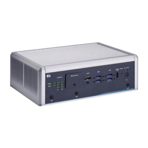
AIE900A-AO Series User’s Manual I/O Outlets The following figures show you the I/O outlets on the front view of the AIE900A-AO. ⚫ Front View Drawing ⚫ Rear View Drawing Introduction... -
Page 19: Packing List
M.2 SSD thermal kit x 1 (for M.2 SSD drive) ⚫ M.2 5G themal kit x 1 (for 5G module) ※ Please visit Axiomtek’s official website to download the latest product manual. Model List Fanless Edge AI System with NVIDIA® Jetson AGX Orin ™ 32GB, AIE900A-AO-2L8P 1 HDMI, 2 2.5GbE, 8 PoE, 6 USB, 8-CH DI/DO, and 2 COM/CAN... - Page 20 AIE900A-AO Series User’s Manual This page is intentionally left blank. Introduction...
-
Page 21: Section 2 Hardware Installation
AIE900A-AO Series User’s Manual SECTION 2 HARDWARE INSTALLATION The AIE900A-AO is convenient for your various hardware configurations, such as SSD (Solid State Drive), M.2 Key E module, M.2 Key B module, and PCI Express Mini Card modules. Chapter 2 will show you how to install the hardware. - Page 22 AIE900A-AO Series User’s Manual Step 4 While holding the PCI Express mini card at a 45-degree angle up from the horizontal, slowly insert the golden fingers into the mini PCI Express slot, until it is fully inserted in place. Step 5 Press the PCI Express mini card down gently, but firmly, and then secure the mini card to the carrier by tightening up one M2 screw to the marked position.
-
Page 23: Installing The M.2 Key B 3042/3052 5G Or Lte Module
AIE900A-AO Series User’s Manual Installing the M.2 Key B 3042/3052 5G or LTE Module Step 1 Turn off the system, and unplug the power adaptor. Step 2 Flip the system upside down and loosen seven screws at the bottom side, as marked with red circles in the figure below. - Page 24 AIE900A-AO Series User’s Manual Step 4 Take the 5G thermal bracket, two thermal pads, and two M3 screws out of the package box. Step 5 Attach the two thermal pads onto the 5G thermal bracket. Note: Thermal Pad dimensions: ...
- Page 25 AIE900A-AO Series User’s Manual Step 6 While holding the M.2 Key B 3052 module at a 30 degree angle up from the horizontal, slowly insert the golden fingers into the M.2 Key B 3042/3052 slot, until it is fully inserted in place.
- Page 26 AIE900A-AO Series User’s Manual Step 8 Refer to the section 2.4: Installing 5G or LTE or Wi-Fi Antenna Cable for the antennas cable installation and management. Step 9 Place the 5G thermal bracket on the M.2 Key B 3052 module, then secure the bracket to the carrier by firmly tightening the two M3 screws to the marked positions.
-
Page 27: Installing The M.2 Key E 2230 Wi-Fi Module
AIE900A-AO Series User’s Manual Installing the M.2 Key E 2230 Wi-Fi Module Step 1 Turn off the system, and unplug the power adaptor. Step 2 Flip the system upside down and loosen seven screws at the bottom side, as marked with red circles in the figure below. - Page 28 AIE900A-AO Series User’s Manual Step 4 While holding the M.2 Key E 2230 module at a 30 degree angle up from the horizontal, slowly insert the golden fingers into the M.2 Key E 2230 slot, until it is fully inserted in place.
-
Page 29: Installing Lte Or Wi-Fi Antenna Cable
AIE900A-AO Series User’s Manual Installing LTE or Wi-Fi Antenna Cable Step 1 Install the Mini PCIe card or M.2 Key E card or M.2 Key B module, and affix it with a screw. For more details, please refer to section 2.1 to 2.3. - Page 30 AIE900A-AO Series User’s Manual Step 2 Take the antenna kit out of its box, and remove the hex nut and washer from the antenna cable. Note: The 5G, LTE and Wi-Fi modules come with a different type of SMA cable, one is IPEX, and another one is IPEX4.
- Page 31 AIE900A-AO Series User’s Manual Step 3 Connect the SMA cables to the PCI Express mini card or the M.2 Key E module or M.2 Key B module. PCI Express mini card M.2 2230 Key E module M.2 3042/3052 Key B module...
- Page 32 AIE900A-AO Series User’s Manual Step 4 Install the antenna cable connectors through the openings on the chassis, put the washer and Hex nut into the antenna cable connector, and then tighten them up. Note: We suggest installing the antenna cables through the openings marked in the figure below for better cable management.
-
Page 33: Installing The M.2 2280 Key M Ssd Drive
AIE900A-AO Series User’s Manual Installing the M.2 2280 Key M SSD Drive Step 1 Turn off the system, and unplug the power adaptor. Step 2 Flip the system upside down and loosen seven screws at the bottom side, as marked with red circles in the figure below. - Page 34 AIE900A-AO Series User’s Manual Step 4 Take the SSD thermal bracket, five thermal pads, and two M3 screws out of the package box. Step 5 Attach the four smaller thermal pads onto the SSD thermal bracket. Note: Thermal Pad dimension: 32mm (L) x 23mm (W) x 0.5mm (H)
- Page 35 AIE900A-AO Series User’s Manual Step 6 Apply the larger thermal pad onto the M.2 2280 Key M slot. Note: Thermal Pad dimension: 60mm (L) x 25mm (W) x 5.5mm (H) Step 7 While holding the M.2 2280 Key M SSD drive at a 30 -degree angle up from the horizontal, slowly insert the golden fingers into the M.2 2280...
- Page 36 AIE900A-AO Series User’s Manual Step 8 Press the M.2 2280 Key M SSD drive down gently, but firmly, and then secure the M.2 2280 Key M SSD drive to the carrier by tightening up one M3 screw to the marked position.
-
Page 37: Section 3 Jumper Setting & Connector
AIE900A-AO Series User’s Manual SECTION 3 JUMPER SETTING & CONNECTOR Proper jumper settings configure the AIE900A-AO to meet your application purpose. This section explains all jumpers and connectors as well as their default settings for onboard devices, respectively. Jumper & Connector Location PSB906 Top View Jumper Setting &... - Page 38 AIE900A-AO Series User’s Manual PSB906 Bottom View Note: We strongly recommended that you should not modify any unmentioned jumper setting without Axiomtek FAE’s instruction. Any modification without instruction might cause damage to the system. Jumper Setting & Connector...
-
Page 39: Connectors
Connectors connect the board with other parts of the system. Loose or improper connection might cause problems. Make sure all connectors are properly and firmly connected. Here is a summary table showing you all connectors and buttons on the AIE900A-AO Series. PCB Location... -
Page 40: Nano Sim Card Slot (Cn1)
AIE900A-AO Series User’s Manual 3.2.1 Nano SIM Card Slot (CN1) AIE900A-AO has a Nano SIM card slot (CN1). To make sure the system functions correctly, you need to use the Nano SIM card along with a 5G/LTE module. Please insert the LTE module into the PCI-Express Mini Card slot (SCN3) for LTE/3G networks. -
Page 41: Hdmi Connector (Cn3)
AIE900A-AO Series User’s Manual 3.2.3 HDMI Connector (CN3) The HDMI (High-Definition Multimedia Interface) is a compact digital interface which is capable of transmitting high-definition video and high-resolution audio over a single cable. Signal Signal HDMI1_DATA2+ HDMI1_DATA2- HDMI1_DATA1+ HDMI1_DATA1- HDMI1_DATA0+ HDMI1_DATA0-... -
Page 42: Microsd Slot (Cn8)
AIE900A-AO Series User’s Manual 3.2.5 MicroSD Slot (CN8) The Micro Secure Digital (SD) is a type of flash memory card format utilized in portable devices such as notebooks and digital cameras. Signal Signal DATA1 +3.3VS DATA0 DATA3 DATA2 3.2.6 Ethernet / PoE Ports (CN20, CN22) The AIE900A-AO is equipped with 10 RJ-45 connectors: CN20 and CN22 (Intel®... -
Page 43: Digital I/O Connector (Female) (Cn21)
AIE900A-AO Series User’s Manual 3.2.7 Digital I/O Connector (Female) (CN21) The AIE900A-AO features a single 8-Channel digital I/O connector, which can be managed through software programming. Signal Signal DIO1 DIO2 DIO3 DIO4 DIO5 DIO6 DIO7 DIO8 3.2.8 USB2.0 Connector (CN23) The Universal Serial Bus connectors are designed to be compliant with the USB 2.0 (480Mbps) -
Page 44: Serial & Can Port Connector (Com1/Can1, Com2/Can2)
AIE900A-AO Series User’s Manual 3.2.9 Serial & CAN Port Connector (COM1/CAN1, COM2/CAN2) AIE900A-AO features two DB9 connectors for two serial ports (RS-232 / RS-422 / RS-485) as well as two CAN-bus ports, with the default setting being RS-232 and CAN-bus. Users have the flexibility to choose between RS-232, RS-422, or RS-485 through command line. -
Page 45: External Fan Kit Connector (Cn25)
AIE900A-AO Series User’s Manual 3.2.10 External Fan Kit Connector (CN25) The AIE900A-AO is designed with an optional external fan kit to enhance AI computing performance and extend the operating temperature range. CN25 serves as the fan connector, making it easy and effortless for users to install and maintain the external fan kit. -
Page 46: 2280 Key M Pcie X4 Ssd Slot (Scn1)
AIE900A-AO Series User’s Manual 3.2.12 M.2 2280 Key M PCIe x4 SSD slot (SCN1) The AIE900A-AO is equipped with one M.2 2280 Key M slot that supports PCI-Express 4.0 x4 NVMe SSD for additional storage capacity. Signal Signal Signal Signal +3.3V... -
Page 47: Pci-Express Mini Card Slot (Scn3)
AIE900A-AO Series User’s Manual 3.2.13 PCI-Express Mini Card Slot (SCN3) The AIE900A-AO features a full-size PCI-Express Mini Card slot known as SCN3. It can handle both PCI-Express and USB 2.0 signals, following the PCI-Express Mini Card Specification Version 1.2. Signal... -
Page 48: 2230 Key E Slot (Scn4)
AIE900A-AO Series User’s Manual 3.2.14 M.2 2230 Key E slot (SCN4) The AIE900A-AO features one M.2 2230 Key E slot designed for Wi-Fi module usage. Signal Signal Signal Signal +3.3V USB_D+ +3.3V USB_D- CONNECTOR KEY E CONNECTOR CONNECTOR CONNECTOR CONNECTOR... -
Page 49: 3042/3052 Key B 5G Module Slot (Scn5)
AIE900A-AO Series User’s Manual 3.2.15 M.2 3042/3052 Key B 5G module slot (SCN5) The AIE900A-AO comes with one M.2 3042/3052 Key B USB3.2 Gen2 (10Gbps) slot for 5G or LTE (CAT6 or above) module. Signal Signal Signal Signal Config_3 +3.3V +3.3V... -
Page 50: Cmos Battery Interface (Bat1)
AIE900A-AO Series User’s Manual 3.2.16 CMOS Battery Interface (BAT1) This connector is used for CMOS battery interface. Signal +VBAT 3.2.17 Debug Port Connector (JP1) CN13 serves as the UART interfac e (UART Port3) for debugging purposes during software development. Signal... -
Page 51: Recovery Mode Switch (Sw2)
AIE900A-AO Series User’s Manual 3.2.19 Recovery Mode Switch (SW2) To flash the image, please switch SW2 to ON before booting up the AIE900A-AO; this action will activate the force recovery mode. Function Description Recovery Mode Normal 3.2.20 Reset Button (SW3) The reset button enables users to restart the AIE900A-AO if the system encounters an issue and is not functioning correctly. -
Page 52: Power And Storage Led Indicator (Led2)
AIE900A-AO Series User’s Manual 3.2.23 Power and Storage LED Indicator (LED2) The upper green LED is linked to M.2 2280 Key M solid state drive (SSD) to receive its activity signal. LED flashes every time SSD is accessed. The lower green LED (Power) is linked to power signal which lights up and will remain lsteady while the system is powered on. -
Page 53: Section 4 Jetpack Sdk Flash Guide
AIE900A-AO Series User’s Manual SECTION 4 JETPACK SDK Flash Guide This section provides users with a detailed description of how to flash NVIDIA JetPack SDK for AIE900A-AO. Users can follow the instructions below to install or reinstall JetPack SDK by themselves. - Page 54 AIE900A-AO Series User’s Manual Step2. Open the terminal at host system, and change the path to the image file directory for example “~/Downloads” with following commands to check image tarball data integrity first. $ cd ~/Downloads $ md5sum -c <image_tarball_file_name>.tbz2.md5sum Command Example: $ md5sum -c mfi_jetson-agx-orin-32GB-JP5.1.1-AIE900A-AO-V1.0.0.tbz2.md5sum...
- Page 55 AIE900A-AO Series User’s Manual Step5. Make sure the recovery switch(SSW2) has been switched to ON, and run the command lsusb, then the command line “0955:7223 Nvidia Corp.” should be listed. $ lsusb Note: "0955:7223 NVidia Corp." for AGX Orin 32GB ...
- Page 56 AIE900A-AO Series User’s Manual Step7. The flashing procedure takes approximately 20 minutes or more. Once finished, you should see “Flash is successful ” as shown below, and AIE900A-AO will automatically reboot, and please switch the recovery switch(SW2) to OFF to return to standard mode.
-
Page 57: Image Information Inquiry Command
AIE900A-AO Series User’s Manual Image Information Inquiry Command axiomtek.sh Running command to inquiry the current image information, image version, L4T version, Linux kernel version, and Ubuntu version. Jetpack SDK Flash Guide... -
Page 58: Jtop - Third-Party Jetson Platform Monitor Tool
AIE900A-AO Series User’s Manual JTOP — Third-party Jetson Platform Monitor Tool JTOP is a third-party system monitoring utility that runs on the terminal and see and control realtime the status of the AIE Series Platform. CPU, RAM, GPU status, power mode management, toolkits version and more. -
Page 59: Appendix Aprogrammable Digital I/O
AIE900A-AO Series User’s Manual APPENDIX A PROGRAMMABLE DIGITAL I/O About Programmable Digital I/O The AIE900A-AO supports 8 channels programmable digital I/O which allows user to program the DI or DO. For more details, please refer to the below sample code. -
Page 60: Sample Program
AIE900A-AO Series User’s Manual Sample Program DIO Output Sample Code # i2cset -f -y 1 0x22 0x01 0xFF //Set DIO1 ~ 8 as High # i2cset -f -y 1 0x22 0x03 0x00 //Set DIO1 ~ 8 as Output # i2cset -f -y 1 0x22 0x01 0xF0... - Page 61 AIE900A-AO Series User’s Manual Register 1 - Output Port Register Bit Description This register reflects the outgoing logic levels of the pins defined as outputs by Register 3. Bit values in this register have no effect on pins defined as inputs. Reads from this register return the value that is in the flip-flop controlling the output selection, not the actual pin value.
Need help?
Do you have a question about the AIE900A-AO Series and is the answer not in the manual?
Questions and answers