Table of Contents
Advertisement
Quick Links
Jumper Settings
Before applying power to AX93291, please make sure all jumper(s) are in
factory default positions.
Jumper
Description
COM1 Data/Power Selection
JP1
Default: RS-232 Data
COM1 Data/Power Selection (JP1)
The COM1 port (CN1) has +5V level power capability on DCD and +12V
level on RI by setting this jumper.
Description
Power: Set CN1 pin 1 to +5V level
Data: Set CN1 pin 1 to DCD (Default)
Power: Set CN1 pin 8 to +12V level
Data: Set CN1 pin 8 to RI (Default)
Assembly Drawing
Gently insert ZIO module into CPU board's ZIO connector, see figure above.
Align assembly holes and use screws to firmly secure ZIO module to CPU
board. Be careful not to over-tighten the screws.
4
Setting
CN1 Pin 1: DCD
3-5 Close
CN1 Pin 8: RI
4-6 Close
Setting
1-3 close
3-5 close
2-4 close
4-6 close
AX93291
94193291000E
©
Copyright 2015 Axiomtek Co., Ltd.
Version A1 April 2015
Printed in Taiwan
AX93291 Quick Installation Guide
Checklist
I/O board x1
Screw pack x1
Quick installation guide x1
Com cable x2
Note: Please contact your local vendors if any damaged or missing items. DO
NOT apply power to the module if there is any damaged component.
Dimension and Fixing Holes
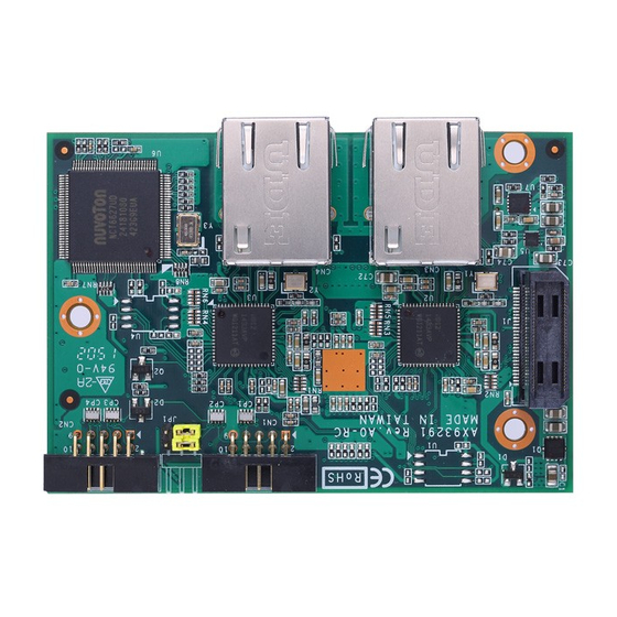
Module Layout
94193291000E
©
Copyright 2015 Axiomtek Co., Ltd.
Version A1 April 2015
Printed in Taiwan
1
Advertisement
Table of Contents

Related Manuals for AXIOMTEK AX93291


Summary of Contents for AXIOMTEK AX93291
- Page 1 AX93291 Quick Installation Guide Jumper Settings Before applying power to AX93291, please make sure all jumper(s) are in factory default positions. Checklist Jumper Description Setting I/O board x1 Screw pack x1 Quick installation guide x1 Com cable x2...
- Page 2 1000 LAN LED (Orange) / 100 LAN No Use LED (Green) No Use No Use No Use 94193291000E 94193291000E © © Copyright 2015 Axiomtek Co., Ltd. Copyright 2015 Axiomtek Co., Ltd. Version A1 April 2015 Version A1 April 2015 Printed in Taiwan Printed in Taiwan...
Need help?
Do you have a question about the AX93291 and is the answer not in the manual?
Questions and answers