Wren Kitchens BASE UNIT 600 Assembly Manual
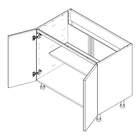
Sink/hob, 1/2 door
Hide thumbs
Also See for BASE UNIT 600:
- Assembly manual (12 pages) ,
- Fittings manual (9 pages) ,
- Assembly manual (8 pages)

Related Manuals for Wren Kitchens BASE UNIT 600


Summary of Contents for Wren Kitchens BASE UNIT 600
- Page 1 BASE UNIT 600 - 1000 Sink/Hob 1/2 Door Assembly Guide 1000 For Internal Use: FI.WR.INS.057_WKIN00145_BASE_600-1000_1-2Dr_Sink/Hob_Rev2.indd...
-
Page 2: Assembly Guide
BASE UNIT BEFORE YOU START INSTALLATION 600 - 1000 Sink/Hob SHOULD BE 1/2 Door PERFORMED BY A Assembly Guide COMPETENT PERSON ONLY. THIS PRODUCT COULD BE DANGEROUS IF INCORRECTLY INSTALLED fi.pk. fit.141 sink rail + screws 600 - *off 800 - *off 1000 - *off Panel A Panel B... - Page 3 BASE UNIT 600 - 1000 Sink/Hob 1/2 Door Step 1. Assembly Guide Seat dowel (F) into holes in both end panels (B) as shown. Seat (G) cam dowel into hole as shown. Step 2. Seat cam dowel (G) into holes in both end panels (B) as shown.
- Page 4 BASE UNIT 600 - 1000 Sink/Hob 1/2 Door Assembly Guide Step 5. Slide back panel (A) into groove of end panels (B). The back Panel (A) is to be modified accordingly to suit Customer Requirements,prior to inserting into cabinet. for 1000 width cabinets, the Back panel.
- Page 5 BASE UNIT 600 - 1000 Sink/Hob Front 1/2 Door Assembly Guide Step 8. Secure each of the legs into place with 2 x 15mm screws (L). 600-800 Width Cabinets, 4 legs 1000 with Cabinets, 5 legs Ensure legs are rotated as shown so that part of it is supporting the end panels (B).
- Page 6 BASE UNIT 600 - 1000 Sink/Hob from top 1/2 Door Assembly Guide 94mm 126mm Step 11. Hinge Plates Attach hinge mounting plate onto both End Panel or panels,(B) as shown, using Screws which are already positioned within the Hinge Plates. 126mm Hinge side or sides to be mounted in accordance to 94mm...
- Page 7 BASE UNIT Step 12. 600 - 1000 Sink/Hob Insert hinge in top & bottom 1/2 Door holes as shown. Assembly Guide Step 13. Secure hinges by tightening 2 x screws with hinge dowels attached. These are already positioned within the hinges. Step 14.
Need help?
Do you have a question about the BASE UNIT 600 and is the answer not in the manual?
Questions and answers