
Subscribe to Our Youtube Channel
Related Manuals for Portwell WADE-8017


Summary of Contents for Portwell WADE-8017
- Page 1 WADE-8017 WADE-8017 Industrial Mini-ITX Board Version 1.9 Copyright © Portwell 2016 WADE-8017 User's Guide...
- Page 2 (3) Update J1-J5 & ADD J6(Page16-17) & J34(Page.27) R1.5 Update support KBL information R1.6 Add support KBL information R1.7 Change title page photo R1.8 Add BIOS socket location(U10) information R1.9 Add H110 information in Block Diagram Copyright © Portwell 2016 WADE-8017 User's Guide...
-
Page 3: Table Of Contents
Intel® Kaby Lake / Sky Lake-S PCH ............................... 32 Main Memory ......................................32 Installing the Single Board Computer ..............................33 6.3.1 Chipset Component Driver ..................................33 6.3.2 Intel® HD Graphics 530 ..................................34 Copyright © Portwell 2016 WADE-8017 User's Guide... - Page 4 Save & Exit ......................................87 Troubleshooting ............................................. 90 Hardware Quick Installation ................................... 90 BIOS Setting ......................................91 FAQ ........................................92 Portwell Software Service ........................................98 Industry Specifications ........................................... 99 10.1 Industry Specifications ................................... 99 Copyright © Portwell 2016 WADE-8017 User's Guide...
- Page 5 Portwell provides no warranty with regard to this user’s guide or any other information contained herein and hereby expressly disclaims any implied warranties of merchantability or fitness for any particular purpose with regard to any of the foregoing. Portwell assumes no liability for any damages incurred directly or indirectly from any technical or typographical errors or omissions contained herein or for discrepancies between the product and the user’s guide.
- Page 6 Warranty”). Portwell may in its sole discretion modify its Limited Warranty at any time and from time to time. Beginning on the date of shipment to its direct customer and continuing for the published warranty period, Portwell represents that the products are new and warrants that each product failing to function properly under normal use, due to a defect in materials or workmanship or due to non conformance to the agreed upon specifications, will be repaired or exchanged, at Portwell’s option and expense.
-
Page 7: Introduction
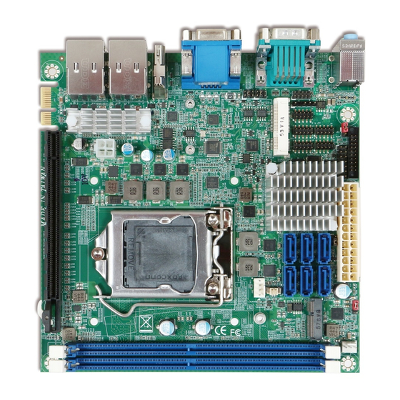
WADE-8017 1 Introduction WADE-8017 based on the Intel® Core™ Processor which offers 14nm Hi-K process technology with energy efficient architecture. WADE-8017 support dual channels DDR4 Long - DIMM up to 32GB. Desktop solution is still popular in the market of DVR and Factory Automation which can fulfill most of these applications; therefore, with high performance and... -
Page 8: Specifications
◆ Supports dual 10/100/1000 Mbps Ethernet port (s) via PCI Express x1 bus which provides 500 MB/s ◆ Ethernet data transmission rate High Drive GPIO One pin-header for GPIO(8bit in &8bit out) ◆ Copyright © Portwell 2016 WADE-8017 User's Guide... -
Page 9: Supported Operating Systems
Power supply voltage: ATX ◆ Board size: 170mm x 170 mm ◆ Supported Operating Systems The WADE-8017 supports the following operating systems. Windows 7/e support Windows 8.1 / WEI 8.1 support Windows 10 full support Kernel.org Distribution Yocto based Embedded Linux Distribution Copyright ©... -
Page 10: Mechanical Dimensions
WADE-8017 Mechanical Dimensions Copyright © Portwell 2016 WADE-8017 User's Guide... -
Page 11: Power Consumption
Power Consumption Test Configuration CPU Type Intel® Core™ i7-6700TE CPU @ 2.4GHz (ES) L3: 8MByte SBC BIOS Portwell, Inc. WADE-8017 TEST BIOS (51104T00) Memory WARIS UB-DIMM DDR4 2133 8GB*2 (SEC K4A4G085WD) VGA Card Onboard Intel® HD Graphics 530 VGA Driver Intel®... -
Page 12: Environmental Specifications
System+ Device +12V 0.97A 1.81A 1.56A System+ Device +5V 1.87A USB2.0 Loading Test 4.98 V/ 570 mA Environmental Specifications Storage Temperature : -20~80°C Operation Temperature : 0~60°C Storage Humidity : 5~90% Operation Humidity: 10~90% Copyright © Portwell 2016 WADE-8017 User's Guide... -
Page 13: Block Diagram
WADE-8017 3 Block Diagram Copyright © Portwell 2016 WADE-8017 User's Guide... -
Page 14: Hardware Configuration
WADE-8017 4 Hardware Configuration Jumpers and Connectors This chapter indicates jumpers’, headers’ and connectors’ locations. Users may find useful information related to hardware settings in this chapter. Copyright © Portwell 2016 WADE-8017 User's Guide... -
Page 15: Jumpers Settings
Jumpers Settings For users to customize WADE-8017’s features. In the following sections, Short means covering a jumper cap over jumper pins; Open or N/C (Not Connected) means removing a jumper cap from jumper pins. Users can refer to Figure 1 for the Jumper allocations. - Page 16 3-1 Short 3-5 Short JP2:COM2RI Select Header PIN No. Signal Description 3-4 Short 3-1 Short 3-5 Short JP3: Mini PCIE & MSATA SETTING PIN No. Signal Description Mini PCIE 1-2 Open MSATA 1-2 Short Copyright © Portwell 2016 WADE-8017 User's Guide...
- Page 17 2-3 Short JP5: Clear CMOS Selection PIN No. Signal Description 1-2 Short 2-3 Short Clear CMOS JP6: H/W write protect PIN No. Signal Description 1-2 Short Disable write protect 2-3 Short Enable write protect Copyright © Portwell 2016 WADE-8017 User's Guide...
-
Page 18: Connector Settings
COM5 Pin Header Mini-PCI-E /MSATA CONNECTOR H110 just only support mSATA COM3 Pin Header COM4 Pin Header USB2.0X2 Pin Header COM6 Pin Header ATX 4P CONNECTOR TPM Pin header Front panel header PCIEx16 CONNECTOR Copyright © Portwell 2016 WADE-8017 User's Guide... - Page 19 SATA CONNECTOR SATA CONNECTOR CPU FAN header BATTERY header M.2 Type E CONNECTOR H110 not support M.2 function SYSTEM FAN header DDR4 UDIMMA Socket DDR4 UDIMMB Socket PCI Express Bifurcation BIOS EEPROM Socket Copyright © Portwell 2016 WADE-8017 User's Guide...
- Page 20 J8: 4in/4out GPIO Pin Header PIN No. Signal Description PIN No. Signal Description GPIO0 GPIO4 GPIO1 GPIO5 GPIO2 GPIO6 GPIO3 GPIO7 VCC5 J9: SMBUS Pin Header PIN No. Signal Description SMB_CLK SMB_DATA VCC5 Copyright © Portwell 2016 WADE-8017 User's Guide...
- Page 21 Signal Description PIN No. Signal Description DCD#5 RXD#5 TXD#5 DTR#5 DSR#5 RTS#5 CTS#5 RI#5 J13: COM3 Pin Header PIN No. Signal Description PIN No. Signal Description DCD#3 RXD#3 TXD#3 DTR#3 DSR#3 RTS#3 CTS#3 RI#3 Copyright © Portwell 2016 WADE-8017 User's Guide...
- Page 22 J14: COM4 Pin Header PIN No. Signal Description PIN No. Signal Description DCD#4 RXD#4 TXD#4 DTR#4 DSR#4 RTS#4 CTS#4 RI#4 J15: USBx2 Pin Header PIN No. Signal Description PIN No. Signal Description VCC_USBH0 VCC_USBH0 Copyright © Portwell 2016 WADE-8017 User's Guide...
- Page 23 WADE-8017 J16: COM6 Pin Header PIN No. Signal Description PIN No. Signal Description DCD#6 RXD#6 TXD#6 DTR#6 DSR#6 RTS#6 CTS#6 RI#6 J17: ATX 4P CONNECTOR PIN No. Signal Description Ground Ground +12V +12V Copyright © Portwell 2016 WADE-8017 User's Guide...
- Page 24 Signal Description CLK_TPM_33M LFRAME# RUF_PLT_RST# LAD3 LAD2 3.3V LAD1 LAD0 SMB_CLK SMB_DATA 3V_DUAL SERIRQ LPCPD J19: Front panel header PIN No. Signal Description PIN No. Signal Description VCC5 5VSB HD_LED# SUSLED PWRBTN RESET# BUZZER# Copyright © Portwell 2016 WADE-8017 User's Guide...
- Page 25 WADE-8017 J21: ATX 24P CONNECTOR PIN No. Signal Description PIN No. Signal Description +3.3V +3.3V +3.3V -12V Ground Ground PS_ON# Ground Ground Ground Ground Ground ATX_PWROK +5VSB +12V1 +12V1 +3.3V Ground Copyright © Portwell 2016 WADE-8017 User's Guide...
- Page 26 Signal Description Ground +12V Fan on/off output Fan Speed control J29: BATTERY CONNECTOR PIN No. Signal Description +3.3V J31: SYSTEM FAN CONNECTOR PIN No. Signal Description Ground Fan speed control Fan on/off output Copyright © Portwell 2016 WADE-8017 User's Guide...
- Page 27 WADE-8017 J34: PCI Express Bifurcation ON=0; OFF=1 PEG Mode PIN[1:2] PCIE 1X8,2X4 PCIE 2X8 PCIE 1X16 Copyright © Portwell 2016 WADE-8017 User's Guide...
-
Page 28: Signal Descriptions
#Define WDTMIN 0x07 //WDT Timer Counter Register (Minute) #Define WDTSEC 0x08 //WDT Timer Counter Register (Second) VOID Write_EC_SRAM(UINT8 Offset,UINT8 Value){ IoWrite8(0xE300+Offset,Value); Byte Read_EC_SRAM(UINT8 Offset){ IoRead8(0xE300+offset,Value); return Value; void WDT() // Enable WDT 30sec Copyright © Portwell 2016 WADE-8017 User's Guide... - Page 29 Write_EC_SRAM(WDTCFG,0x01); //Bit0: WDT Enable, BIT1: 0:Second Mode // Enable WDT 5min Write_EC_SRAM(WDTSEC,5); Write_EC_SRAM(WDTCFG,0x03); //Bit0: WDT Enable, BIT1: 1:Minute Mode // Enable WDT 10min, 20sec Write_EC_SRAM(WDTSEC,20); Write_EC_SRAM(WDTSEC,10); Write_EC_SRAM(WDTCFG,0x03); //Bit0: WDT Enable, BIT1: 1:Minute Mode Copyright © Portwell 2016 WADE-8017 User's Guide...
-
Page 30: Gpio Signal
#Define GPDR 0x2C //GPIO Data Register, Bit7 = GPIO7, Bit6 = GPIO6, ..., 0: Low; 1: High VOID Write_EC_SRAM(UINT8 Offset,UINT8 Value){ IoWrite8(0xE300+Offset,Value); Byte Read_EC_SRAM(UINT8 Offset){ IoRead8(0xE300+offset,Value); return Value; void GPIO() int Temp; // Get GPIO data Temp = Read_EC_SRAM(GPDR); // Set GPIO7 High Temp |= 0x80; Copyright © Portwell 2016 WADE-8017 User's Guide... - Page 31 WADE-8017 Write_EC_SRAM(GPDR,Temp); //Bit7: GPIO7 status, 0: Low 1: High Copyright © Portwell 2016 WADE-8017 User's Guide...
-
Page 32: System Resources
Intel® C236 Chipset (Intel® GL82C236 PCH) Main Memory WADE-8017 provides 2 x 260-pin Long-DIMM sockets which supports DDR4 ECC/non-ECC memory. The maximum memory can be up to 32GB. Memory clock and related settings can be detected by BIOS via SPD interface. -
Page 33: Installing The Single Board Computer
Chipset Component Driver WADE-8017 is based on Intel® Q170/H110/C236 chipset and desktop processors including Core™ i7 / i5 / i3 sku . It’s a new chipset that some old operating systems might not be able to recognize. To overcome this compatibility issue, for Windows Operating Systems such as Windows 8, please install its INF before any of other Drivers are installed. -
Page 34: Intel® Hd Graphics 530
Intel® HD Graphics 530 WADE-8017 has integrated Intel® HD Graphics 530 which supports DirectX 12、OpenCL 2.0、OpenGL 4.4. It is the most advanced design to gain an outstanding graphic performance. WADE-8017 supports VGA, DP, HDMI display output. This combination makes WADE-8017 an excellent performance hardware. -
Page 35: Bios Setup Items
The BIOS setup program provides a General Help screen. The menu can be easily called up from any menu by pressing <F1>. The Help screen lists all the possible keys to use and the selections for the highlighted item. Press <Esc> to exit the Help Screen. Copyright © Portwell 2016 WADE-8017... - Page 36 WADE-8017 Copyright © Portwell 2016 WADE-8017 User's Guide...
-
Page 37: Main
The date format is <Day>, <Month> <Date> <Year>. Use [+] or [-] to configure system Date. System Date The time format is <Hour> <Minute> <Second>. Use [+] or [-] to configure system Time. System Time Copyright © Portwell 2016 WADE-8017 User's Guide... -
Page 38: Configuration
WADE-8017 7.2.2 Configuration Use this menu to set up the items of special enhanced features Copyright © Portwell 2016 WADE-8017 User's Guide... - Page 39 WADE-8017 CPU Configuration CPU Configuration Parameters Copyright © Portwell 2016 WADE-8017 User's Guide...
- Page 40 Disable – Sets bit 30 of POWER_CTL MSR(0x1FC) to 1 to disable the C State Pre-Wake Disa bled, Enabled C0/C1, C2, C3, C6, C7, C7s, Package C State limit Package C State limit ★ AUTO ★ CFG lock Configure MSR 0xE2[15], CFG lock bit. Disabled, Enabled Copyright © Portwell 2016 WADE-8017 User's Guide...
- Page 41 WADE-8017 Chipset Configuration Configuration Chipset feature Copyright © Portwell 2016 WADE-8017 User's Guide...
- Page 42 Disabled, ★ Enabled HD Audio Disabled = HAD will be unconditionally disabled Enabled = HAD will be unconditionally Enabled ★ LPC Bus, PCIE Bus Port 80h Redirection Control where the port 80h cycles are sent. Copyright © Portwell 2016 WADE-8017 User's Guide...
- Page 43 WADE-8017 AMT Configuration Configure Active Management Technology Parameters Copyright © Portwell 2016 WADE-8017 User's Guide...
- Page 44 This option just controls the BIOS extension execution. If enabled, this requires additional firmware in the SPI device ★ Disabled, Enabled Un-Configure ME OEMFlag Bit 15: Un-Configure ME without password. LAN Configuration Configuration on Board LAN device. Copyright © Portwell 2016 WADE-8017 User's Guide...
- Page 45 WADE-8017 Copyright © Portwell 2016 WADE-8017 User's Guide...
- Page 46 Intel I210 LAN Controller. Launch Legacy PXE Rom. [Disable] Not launch Rom, [Enable] Force launch Rom, [Auto] ★ Disable, Enable, Auto Launch Legacy PXE Rom Auto detect LAN Cable state to Enable/Disable Rom initial. Copyright © Portwell 2016 WADE-8017 User's Guide...
- Page 47 WADE-8017 Graphics Configuration Configuration Graphics Settings Copyright © Portwell 2016 WADE-8017 User's Guide...
- Page 48 Select the Video Device which will be activated during POST. This has no effect if external Primary IGFX Boot Display graphics present. Secondary boot display selection will appear based on your selection. HDMI Copyright © Portwell 2016 WADE-8017 User's Guide...
- Page 49 WADE-8017 VGA modes will be supported only on primary display ★ Disabled, DP, VGA, Secondary IGFX Boot Select Secondary Display Device Display HDMI Copyright © Portwell 2016 WADE-8017 User's Guide...
- Page 50 WADE-8017 PCI/PCIE Configuration PCI, PCI-X and PCI Express Settings. Copyright © Portwell 2016 WADE-8017 User's Guide...
- Page 51 Enable or disable PCI Express Clock Gating for each root port. Enable/Disable the control of Active State Power Management on SA side of the DMI Link. Disabled ★ Enabled DMI Link ASPM Control Copyright © Portwell 2016 WADE-8017 User's Guide...
- Page 52 WADE-8017 PCI Express Root Port4, 6-8, 11, 13-18 PCI Express Root Port 4, 6-8, 11, 13-18 Copyright © Portwell 2016 WADE-8017 User's Guide...
- Page 53 ★ Disabled, L0s, L1, L0sL1, Set the ASPM Level: Force L0s – Force all links to L0s State AUTO-BIOS auto ASPM Support configure, DISABLE – Disables ASPM Auto ★ Auto,Gen1,Gen2,Gen3 PCIe Speed Select PCI Express port speed Copyright © Portwell 2016 WADE-8017 User's Guide...
- Page 54 WADE-8017 SATA Configuration SATA Device Options Settings Copyright © Portwell 2016 WADE-8017 User's Guide...
- Page 55 Designates this port as Hot Pluggable ★ Disabled, Enabled External SATA External SATA Support. ★ hard Disk Drive, Solid State SATA Device Type Indentify the SATA port is connected to Solid State Drive or Hard Disk Drive. Drive Copyright © Portwell 2016 WADE-8017 User's Guide...
- Page 56 WADE-8017 USB Configuration USB Configuration Parameters. Copyright © Portwell 2016 WADE-8017 User's Guide...
- Page 57 This is workaround for OSes without XHCI hand-off support. The XHCI ownership change Enabled, ★ Disabled XHCI Hand-off should be claimed by XHCI driver. USB Mass Storage Driver Disabled, ★ Enabled Enable/Disable USB Mass Storage Driver Support. Support Copyright © Portwell 2016 WADE-8017 User's Guide...
- Page 58 WADE-8017 PCH USB Configuration PCH USB Configurtion Copyright © Portwell 2016 WADE-8017 User's Guide...
- Page 59 ★ Enabled, Disabled USB SS Physical Connector #0-9 Enable /Disable USB port. USB HS Physical Connector #0-5, Disabled, ★ Enabled Precondition work on USB host controller and root ports for faster enumeration. 10-11 Copyright © Portwell 2016 WADE-8017 User's Guide...
- Page 60 WADE-8017 Power Control Configuration System Power Control Configuration Parameters Copyright © Portwell 2016 WADE-8017 User's Guide...
- Page 61 Select 0 for daily system wake up 1-31 for which day of the month that you would like the Wake up day system to wake up Wake up Time(HH: mm: ss) Use [Enter], [TAB] to select field, HH: 0-23, mm: 0-59, ss: 0-59 Copyright © Portwell 2016 WADE-8017 User's Guide...
- Page 62 WADE-8017 TPM Configuration Trusted Computing settings Copyright © Portwell 2016 WADE-8017 User's Guide...
- Page 63 TPM 1.2 will restrict support to TPM 1.2 devices, TPM 2.0 will restrict support to TPM 2.0 ★ Device Select devices, Auto will support both with the default set to TPM 2.0 devices if not found, TPM 1.2 TPM 1.2, TPM 2.0, Auto devices will be enumerated. Copyright © Portwell 2016 WADE-8017 User's Guide...
- Page 64 WADE-8017 Super IO Configuration System Super IO Chip Parameters. Copyright © Portwell 2016 WADE-8017 User's Guide...
- Page 65 Feature Description Options Watch Dog Timer ★ Disabled, Enabled Enable/Disable Watch Dog Timer (Enabled) ★ Second, Minute Timer Unit Select Timer count unit of WDT ★ 20 Timer value Set WDT Timer value Copyright © Portwell 2016 WADE-8017 User's Guide...
- Page 66 WADE-8017 Serial Port 1 Configuration Set Parameters of Serial Port 1 (COMA) Copyright © Portwell 2016 WADE-8017 User's Guide...
- Page 67 Disabled, ★ Enabled Serial Port Enable or Disable Serial Port (COM) ★ Auto, IO=3F8h; IRQ=4; IO=3F8h; IRQ=3,4,5,6,7,9,10,11,12 Change Settings Select an optimal settings for Super IO Device IO=2F8h; IRQ=3,4,5,6,7,9,10,11,12 IO=3E8h; IRQ=3,4,5,6,7,9,10,11,12 IO=2E8h; IRQ=3,4,5,6,7,9,10,11,12 Copyright © Portwell 2016 WADE-8017 User's Guide...
- Page 68 WADE-8017 Serial Port 2 Configuration Set Parameters of Serial Port 2 (COMB) Copyright © Portwell 2016 WADE-8017 User's Guide...
- Page 69 RS-485/422 FULL DUPLEX ★ Auto, IO=2F8h; IRQ=3; IO=3F8h; IRQ=3,4,5,6,7,9,10,11,12 Change Settings Select an optimal settings for Super IO Device. IO=2F8h; IRQ=3,4,5,6,7,9,10,11,12 IO=3E8h;IRQ=3,4,5,6,7,9,10,11,12 IO=2E8h;IRQ=3,4,5,6,7,9,10,11,12 Serial Port 3 Configuration Set Parameters of Serial Port 3 (COMC) Copyright © Portwell 2016 WADE-8017 User's Guide...
- Page 70 WADE-8017 Copyright © Portwell 2016 WADE-8017 User's Guide...
- Page 71 IrDA Active pulse 1.6 uS, Half Duplex, Change Settings Select an optimal setting for Super IO Device IrDA Active pulse 3/16 bit time, Full Duplex, IrDA Active pulse 3/16 bit time, Half Duplex Copyright © Portwell 2016 WADE-8017 User's Guide...
- Page 72 WADE-8017 Serial Port 4 Configuration Set Parameters of Serial Port 4 (COMD) Copyright © Portwell 2016 WADE-8017 User's Guide...
- Page 73 Serial Port RS485 Mode Enable is RS485 Mode and Disable is RS232 Mode Auto, ★ IO=248h; IRQ=11, IO=240h; IRQ=3,4,5,6,7,10,11,12; Change Settings Select an optimal settings for super IO Device IO=248h; IRQ=3,4,5,6,7,10,11,12; IO=250h; IRQ=3,4,5,6,7,10,11,12; IO=258h; IRQ=3,4,5,6,7,10,11,12; Copyright © Portwell 2016 WADE-8017 User's Guide...
- Page 74 WADE-8017 Serial Port 5 Configuration Set Parameters of Serial Port 5 (COME) Copyright © Portwell 2016 WADE-8017 User's Guide...
- Page 75 Serial Port RS485 Mode Enable is RS485 Mode and Disable is RS232 Mode Auto, ★ IO=250h; IRQ=10, IO=240h; IRQ=3,4,5,6,7,10,11,12; Change Settings Select an optimal settings for super IO Device IO=248h; IRQ=3,4,5,6,7,10,11,12; IO=250h; IRQ=3,4,5,6,7,10,11,12; IO=258h; IRQ=3,4,5,6,7,10,11,12; Copyright © Portwell 2016 WADE-8017 User's Guide...
- Page 76 WADE-8017 Serial Port 6 Configuration Set Parameters of Serial Port 6 (COMF) Copyright © Portwell 2016 WADE-8017 User's Guide...
- Page 77 Serial Port RS485 Mode Enable is RS485 Mode and Disable is RS232 Mode Auto, ★ IO=258h; IRQ=10, IO=240h; IRQ=3,4,5,6,7,10,11,12; Change Settings Select an optimal settings for Super IO Device IO=248h; IRQ=3,4,5,6,7,10,11,12; IO=250h; IRQ=3,4,5,6,7,10,11,12; IO=258h; IRQ=3,4,5,6,7,10,11,12; Copyright © Portwell 2016 WADE-8017 User's Guide...
- Page 78 WADE-8017 H/W Monitor Configuration Monitor hardware status Copyright © Portwell 2016 WADE-8017 User's Guide...
- Page 79 CPU Full Fan Target Temperature. ★ Disabled, Enabled Smart System Fan Function Enable or Disable Smart System Fan System Start Target Temp System Start Fan Target Temperature. System Full Target Temp System Full Fan Target Temperature. Copyright © Portwell 2016 WADE-8017 User's Guide...
- Page 80 WADE-8017 Serial Port Console Redirection Serial Port Console Redirection Copyright © Portwell 2016 WADE-8017 User's Guide...
- Page 81 WADE-8017 Feature Description Options Console Redirection (COM 0-5) ★ Disabled, Enabled Console Redirection Enable or Disable. (Enabled) Copyright © Portwell 2016 WADE-8017 User's Guide...
- Page 82 WADE-8017 COM 0-5 Serial Port Console Redirection Serial Port Console Redirection Copyright © Portwell 2016 WADE-8017 User's Guide...
- Page 83 The settings specify if BootLoader is selected then Legacy console redirection ★ Always Enable, BootLoader Redirection After BIOS POST is disabled before booting to legacy OS. Default value is Always Enable with means Legacy console Redirection is enabled for Legacy OS. Copyright © Portwell 2016 WADE-8017 User's Guide...
-
Page 84: Security
This section lets you set security passwords to control access to the system at boot t ime a n d/ o r whe n en t erin g t h e B I OS se tu p pro g ra m. Copyright © Portwell 2016... - Page 85 [Setup] check password when enter setup screen. [Power on] check password on ★ Setup, Power on Password Check Mode every time system power on. Administrator Password Set Administrator Password HDD Security HDD Security Configuration for selected drive. Copyright © Portwell 2016 WADE-8017 User's Guide...
-
Page 86: Boot
WADE-8017 7.2.4 Boot Use this menu to specify the priority of boot devices. Copyright © Portwell 2016 WADE-8017 User's Guide... -
Page 87: Save & Exit
★ Disabled, Enabled Fast Boot launch active boot option. Has no effect for BBS boot options. ★ Legacy only, UEFI only Boot option filter This option controls Legacy/UEFI ROMs priority 7.2.5 Save & Exit Copyright © Portwell 2016 WADE-8017 User's Guide... - Page 88 WADE-8017 Copyright © Portwell 2016 WADE-8017 User's Guide...
- Page 89 UEFI: Built-in EFI Shell Reset the system after saving the changes. (Boot option filter: UEFI only) Attempts to Launch EFI Shell application (Shell.efi) from one of the available Launch EFI Shell from filesystem device filesystem devices. Copyright © Portwell 2016 WADE-8017 User's Guide...
-
Page 90: Troubleshooting
WADE-8017 8 Troubleshooting This section provides a few useful tips to quickly get WADE-8017 running with success. This section will primarily focus on system integration issues, in terms of BIOS setting, and OS diagnostics. Hardware Quick Installation ATX Power Setting Unlike other Single board computer, WADE-8017 supports ATX only. -
Page 91: Bios Setting
The installation of Serial ATA is simpler and easier than IDE, because SATA hard disk doesn’t require setting up Master and Slave, which can reduce mistake of hardware installation. WADE-8017 can support six SATA interface (SATAII, 3.0Gb/s) on board. It has six J22 ,J23, J24, J25, J26, J27 SATA ports on board.(WADE-8017-H110 just support four J23, J25, J26, J27 SATA ports on board.) WADE-8017 also supports one mSATA socket (mini-PCIe slot) (mSATA and SATA port function only can choose one function at the same time. -
Page 92: Faq
Question: I forgot my password of system BIOS, what am I supposed to do? Answer: You can switch off your power supply then find the JP5 on the WADE-8017 board to set it from 1-2 short to 2-3 short and wait 5 seconds to clean your password then set it back to 1-2 short to switch on your power supply. - Page 93 WADE-8017 Question: How to update the BIOS file of WADE-8017? Answer: 1. Please visit web site of Portwell download center as below hyperlink http://www.portwell.com.tw/support/download_center.php Registering an account in advance is a must. (The E-Mail box should be an existing Company email address that you check regularly.) http://www.portwell.com.tw/member/newmember.php...
- Page 94 WADE-8017 DOS MODE: update.bat SHELL MODE: SHELL MODE Copyright © Portwell 2016 WADE-8017 User's Guide...
- Page 95 6. When you see the “FPT Operation Passed” message, which means the BIOS update processes finished. Please cut the AC power off and wait for 10 seconds before powering on. DOS MODE: update.bat SHELL MODE: SHELL MODE Copyright © Portwell 2016 WADE-8017 User's Guide...
- Page 96 BIOS setup menu and switch to “Save & Exit” page then select “Restore Defaults” option and press “Yes” then select “Save Changes and Reset” to finish all BIOS update processes. Copyright © Portwell 2016 WADE-8017 User's Guide...
- Page 97 WADE-8017 Question: What are the display options while using WADE-8017 board? Answer: -The Motherboard supports one VGA port on rear I/O (DP to VGA: Port 0) -The Motherboard supports one HDMI port on rear I/O -The Motherboard supports one DP port on rear I/O and support DP++ (DP to DP:Port 2) Note: Please visit our Download Center to get the Catalog, User manual, BIOS, and driver files.
-
Page 98: Portwell Software Service
Portwell. Portwell BIOS web Tool (PBT) The Portwell BIOS web Tool (PBT) is a brand new on-line utility which innovated by Portwell. PBT now is available for Portwell's premiere customers who are able to add customized BIOS logo and change BIOS default settings on American Megatrends (AMI) BIOS. -
Page 99: Industry Specifications
WADE-8017 10 Industry Specifications 10.1 Industry Specifications The list below provides links to industry specifications that apply to Portwell modules. Low Pin Count Interface Specification, Revision 1.0 (LPC) http://www.intel.com/design/chipsets/industry/lpc.htm Universal Serial Bus (USB) Specification, Revision 2.0 http://www.usb.org/home PCI Specification, Revision 2.3 https://www.pcisig.com/specifications...
Need help?
Do you have a question about the WADE-8017 and is the answer not in the manual?
Questions and answers