
Related Manuals for Portwell WEBS-21G0


Summary of Contents for Portwell WEBS-21G0
- Page 1 WEBS-21G0 Fan-less Embedded System User's Manual Version 1.1 Copyright © Portwell, Inc., 2021. All rights reserved. All other brand names are registered trademarks of their respective owners.
-
Page 2: Table Of Contents
Preface Table of Contents How to Use This Manual Chapter 1 System Overview ....................... 1-1 1.1 Introduction ....................... 1-1 1.2 Check List ......................1-1 1.3 Product Specification ..................1-2 1.4 Mechanical Dimension ..................1-3 Chapter 2 System Installation ....................2-1 2.1 M.2 Key M 2280 Device Installation ..............2-1 2.2 M.2 Key E 2230 Device Installation .............. -
Page 3: How To Use This Manual
Preface How to Use This Manual The manual describes how to configure WEBS-2190 system to meet various operating requirements. It is divided into five chapters, with each chapter addressing a basic concept and operation of Fan-less Embedded System. Chapter 1: System Overview. Present what may have in the box and give an overview of the product specifications and basic system architecture for this fan-less embedded system. -
Page 4: Chapter 1 System Overview
RS-232/422/485 selected by BIOS; one audio combo jack to support Line-out and Mic-in; and M.2 2280 key M storage. In addition, the compact 150mm x 150mm x 63mm box, WEBS-21G0, integrates a M.2 2230 key E socket interface to support WIFI, Bluetooth, making it an ideal solution as an IoT gateway. -
Page 5: Product Specification
System Overview If any of these items is damaged or missing, please contact your vendor and keep all packing materials for future replacement and maintenance. 1.3 Product Specification System NANO-6051 System Chipset Intel Whiskey Lake - U SoC ® Intel Core i5-8365UE (15W) in FCBGA1528 package ®... -
Page 6: Mechanical Dimension
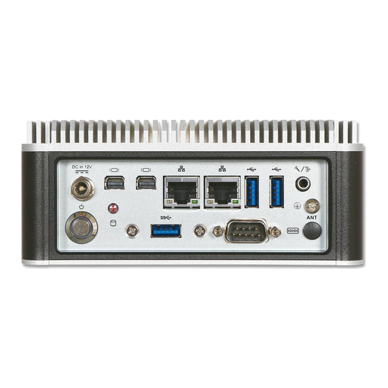
1.4 Mechanical Dimension Front view of the WEBS-21G0 system (standard) Front view of the WEBS-21G0 system (with optional kit: addition 2x USB 3.0) Front view of the WEBS-21G0 system (with optional kit: DIN-Rail mounting) Rear view of the WEBS-21G0 system... - Page 7 System Overview Side view of the WEBS-21G0 system Top view of the WEBS-21G0 system WEB-21G0 User’s Manual...
-
Page 8: Chapter 2 System Installation
System Installation Chapter 2 System Installation This chapter provides you with instructions to set up your system. Definitions and locations of all the interfaces are described so that you can easily configure your system. For more detailed PIN assignment and jumper setting, please refer to user’s manual of NANO-6051. -
Page 9: Key E 2230 Device Installation
System Installation 2.2 M.2 Key E 2230 Device Installation It is easy to install and maintain the 1x M.2 Key E 2230 device by just opening the back cover. Step 1. Loosen the 4 screws of the back Step 2. Take out the back cover cover Step Assemble... -
Page 10: Din Rail Mounting Device Installation
System Installation 2.3 DIN Rail Mounting Device Installation It is easy to install and maintain the Din Rail mounting device by just opening the back cover. Step 1. Loosen the 4 screws of the back Step 2. Take out the back cover cover Step 3. -
Page 11: Getting Started
System Installation 2.4 Getting Started It is easy to get the system started. Step 1. Make sure the power supply Step 2. Press the power button to turn (12V) is connected properly on the system WEB-21G0 User’s Manual... -
Page 12: I/O Interfaces
System Installation 2.5 I/O Interfaces 2.5.1 Front View (Standard) 2.5.2 Front View (Optional Kit: Additional 2x USB 3.0) 2.5.3 Rear View DC in: (12V) Using the provided DC source to connect to the system WEB-21G0 User’s Manual... - Page 13 System Installation Power Button: Press the power button to turn ON/OFF the system HDD LED: Shows real-time read and write activity of your HDD/SSD as a small blinking indicator Mini DP: Mini DP (Display Port) display output LAN: Two Gigabit Ethernet (10/100/1000 Mbits/sec) LAN ports by using Intel I219LM + I210AT Ethernet Controller USB 3.0: Three USB 3.0 (Universal Serial Bus) port...
-
Page 14: Chapter 3 Bios Setup Information
Chapter 3 BIOS Setup Information WEBS-21G0 system adopts NANO-6051 mother board. The following section describes the BIOS setup program. The BIOS setup program can be used to view and change the BIOS settings for the module. Only experienced users should change the default BIOS settings. -
Page 15: Main
Important Instructions Main Use this menu for basic system configurations, such as time, date etc. WEB-21G0 User’s Manual... - Page 16 Important Instructions Feature Description Options The date format is <Day>, <Month> <Date> <Year>. Use [+] System Date or [-] to configure system Date. The time format is <Hour> <Minute> <Second>. Use [+] or System Time [-] to configure system Time. WEB-21G0 User’s Manual...
-
Page 17: Configuration
Important Instructions Configuration Use this menu to set up the items of special enhanced features CPU Configuration CPU Configuration Parameters WEB-21G0 User’s Manual... - Page 18 Important Instructions Feature Description Options Active Processor Number of cores to enable in each processor package. ★All, 1 Cores ★ Hyper-Threading Enable or Disable Hyper-Threading Technology Enabled ,Disabled ★ Max Non-Turbo Boot performance Select the performance state that the BIOS will set Performance, mode starting from reset vector...
- Page 19 Important Instructions Chipset Configuration Configuration Chipset feature Feature Description Options Enabled, ★ VT-d VT-d Capability Disabled Enable/Disable above 4GB MemoryMappedIO BIOS Above Disabled, assignment ★ MMIO BIOS This is enabled automatically when Aperture Size is set to Enabled assignment 2048MB Enabled, ★...
- Page 20 Important Instructions AMT Configuration Configure Intel® Active Management Technology Parameters Feature Description Options When disable AMT BIOS Features are no longer Enabled, BIOS supported and user is no longer able to access MEBx ★ Features Setup. Note: This option does not disable Manageability Disabled Features in FW Disabled,...
- Page 21 Important Instructions Graphics Configuration Configuration Graphics Settings Feature Description Options Select which IGFX/PEG/PCI Graphics device should Primary Display ★Auto, IGFX, PEG, PCI Primary Display select SG for Switchable Gfx. Keep IGFX enable Internal Graphics based on the setup ★Auto, Disable, Enable options.
- Page 22 Important Instructions Power Control Configuration System Power Control Configuration Parameters Feature Description Options Enables or Disables System ability Hibernate (OS/S4 ★Enabled , Disabled Enable Hibernation Sleep State). This option may be not effective with some operating systems. Select highest ACPI sleep state the ★S3 (Suspend to RAM), Suspend Disabled ACPI Sleep State system will enter when...
- Page 23 Important Instructions PCI/PCIE Configuration PCI Express Root Port Settings. PCI Express Root Port8, Port9, Port14 Feature Description Options PCI Express Root Port Control the PCI Express Root ★Enabled , Disabled 8/9/14 Port. Set the ASPM Level: Force L0s – Force all links to ASPM 8/9/14 L0s State ★Auto ,Disabled, L0s, L1, L0sL1,...
- Page 24 Important Instructions LAN Configuration Configuration on Board LAN device. Feature Description Options ★Enabled , Disabled PCH LAN Controller Enable /Disable onboard NIC Enable/Disable integrated LAN to wake ★Enabled , Disabled Wake on LAN the system. Enable or Disable I ntel I210 LAN ★Enabled , Disabled Intel I210 LAN Controller Controller#1.
- Page 25 Important Instructions disable, IPv6 HTTP boot support will not be available. Support to Enable/Disable IPSEC ★Enabled , Disabled IPSEC Certificate certificate for Ikev Wait time in seconds to press ESC key to PXE boot wait time abort the PXE boot. Use either +/- or ★0 numeric keys to set value.
- Page 26 Important Instructions USB Configuration USB Configuration Parameters Feature Description Options SS/HS Enable/Disable this USB Physical Connector. Once Enabled Physical ★ disable, any USB devices plug into the connector will not Connector Disabled be detected by BIOS or OS #0~5,#9 Enables Legacy USB support. AUTO option disables Enabled Legacy legacy support if no USB devices are connected.
- Page 27 Important Instructions TPM Configuration Trusted Computing Setting Feature Description Options Enables or Disables BIOS support for security device. Enabled Security Device ★ O.S. will not show Security Device. TCG EFI protocol Support Disabled and INT1A Interface will not be available. SHA-1 Enabled ★...
- Page 28 Important Instructions TPM 1.2 will restrict support to TPM 1.2 devices, TPM ★ Auto, TPM 1.2, 2.0 will restrict support to TPM 2.0 devices, Auto will Device Select support both with the default set to TPM 2.0 devices if TPM 2.0 not found, TPM 1.2 devices will be enumerated.
- Page 29 Important Instructions Control Option HALF DUPLEX,RS-422 FULL DUPLAX Auto, IO=3F8h; ★ IRQ=4, IO=3F8h; IRQ=3,4,5,6,7,9,10,1 1,12 IO=2F8h; Change Settings Select an optimal settings for Super IO Device IRQ=3,4,5,6,7,9,10,1 1,12 IO=3E8h; IRQ=3,4,5,6,7,9,10,1 1,12 IO=2E8h; IRQ=3,4,5,6,7,9,10,1 1,12 WEB-21G0 User’s Manual 3-16...
- Page 30 Important Instructions H/W Monitor Monitor hardware status Serial Port Console Redirection Serial Port Console Redirection WEB-21G0 User’s Manual 3-17...
- Page 31 Important Instructions Feature Description Options Console Redirection Enable or ★Disabled, Enabled Console Redirection Disable Console Redirection Settings Feature Description Options Emulation: ANSI: Extended ASCII char set. VT100: ASCII char set. VT100+: Extends ★ ANSI, VT100, VT100+, Terminal Type VT100 to support color, function keys, etc. VT-UTF8 VT-UTF8: Uses UTF8 encoding to map Unicode chars onto 1 or more bytes.
- Page 32 Important Instructions more than 1 stop bit. Flow control can prevent data loss from buffer overflow. When sending data, if the receiving buffers are full, a ‘stop’ signal can be sent to Flow Control stop the data flow. Once the buffers are ★None, Hardware RTS/CTS empty, a ‘start’...
-
Page 33: Security
Important Instructions 3.4 Security Feature Description Options [Setup] check password when enter setup ★Setup, Power on Password Check Mode screen. [Power on] check password on every time system power on. Administrator Password Set Administrator Password WEB-21G0 User’s Manual 3-20... -
Page 34: Boot
Important Instructions 3.5 Boot Feature Description Options Number of seconds to wait for setup Setup Prompt Timeout activation key. 65535(0xFFFF) means ★1 indefinite waiting. ★On, Off Bootup NumLock State Select the keyboard NumLock state Enable/Disable CSM support. Note: if you Disabled, ★... - Page 35 Important Instructions CD/DVD,SD,USB Device, Network, Disabled Specifies the Boot Device Priority UEFI Application Boot Priorities sequence from available UEFI Application 3.6 Save & Exit Feature Description Options Reset the system after saving the Save Changes and Reset changes. Reset system setup without saving any Discard Changes and Reset changes.
- Page 36 It is recommended to do this so you can be sure the system is running with the BIOS setting that Portwell has highly endorsed. As a matter of fact, users can load the default BIOS setting at any time when system appears to be unstable in boot up sequence.
-
Page 37: Chapter 4 Important Instructions
In the event of damage to the system unit caused by failure to abide by the hints in this manual and on the unit (especially the safety instructions), Portwell, Inc. shall not be required to respect the warranty even during the warranty period and shall be free from the statutory accident liability obligation. -
Page 38: Chapter 5 Frequent Asked Questions
Clean CMOS Question: How to update the BIOS file of NANO-6051? Answer: 1. Please visit web site of Portwell download center as below hyperlink http://www.portwell.com.tw/support/download_center.php Registering an account in advance is a must. (The E-Mail box should be an existing Company email address that you check regularly.) - Page 39 E-mail: Portwell Korea, Inc. info@portwell.co.kr E-mail: Portwell Latin America vendas@portwell.com.br Industry Specifications The list below provides links to industry specifications that apply to Portwell modules. Count Interface Specification, Revision (LPC) http://www.intel.com/design/chipsets/industry/lpc.htm Universal Serial Bus (USB) Specification, Revision 2.0 http://www.usb.org/home PCI Specification, Revision 2.3...
Need help?
Do you have a question about the WEBS-21G0 and is the answer not in the manual?
Questions and answers