
Related Manuals for Portwell WEBS-21I0


Summary of Contents for Portwell WEBS-21I0
- Page 1 WEBS-21I0 Fan-less Embedded System User's Manual Version 1.1 Copyright © Portwell, Inc., 2022. All rights reserved. All other brand names are registered trademarks of their respective owners.
-
Page 2: Table Of Contents
Preface Table of Contents How to Use This Manual Chapter 1 System Overview ....................... 1-1 1.1 Introduction ........................1-1 1.2 Check List ........................1-1 1.3 Product Specification ....................1-2 1.4 Mechanical Dimension ....................1-3 Chapter 2 System Installation ....................2-1 2.1 Storage mSATA Device Installation ................ -
Page 3: How To Use This Manual
Preface How to Use This Manual The manual describes how to configure WEBS-21I0 system to meet various operating requirements. It is divided into five chapters, with each chapter addressing a basic concept and operation of Fan-less Embedded System. Chapter 1: System Overview. Present what may have in the box and give an overview of the product specifications and basic system architecture for this fan-less embedded system. -
Page 4: Chapter 1 System Overview
Mic-in; and one SATA III port, one mSATA socket and one Micro-SD for storage. In addition, the compact 150mm x 150mm x 66mm box, WEBS-21I0, integrates a M.2 2230 key E socket interface to support WIFI, Bluetooth or LTE module making it an ideal solution as an IoT gateway. -
Page 5: Product Specification
System Overview If any of these items is damaged or missing, please contact your vendor and keep all packing materials for future replacement and maintenance. 1.3 Product Specification System NANO-6063 Intel Atom® Dual/Quad-core x6000E family SoC BIOS AMI uEFI BIOS (SPI ROM) System Memory DDR4 3200 MT/s Non-ECC SO-DIMM up to 32GB Storage... -
Page 6: Mechanical Dimension
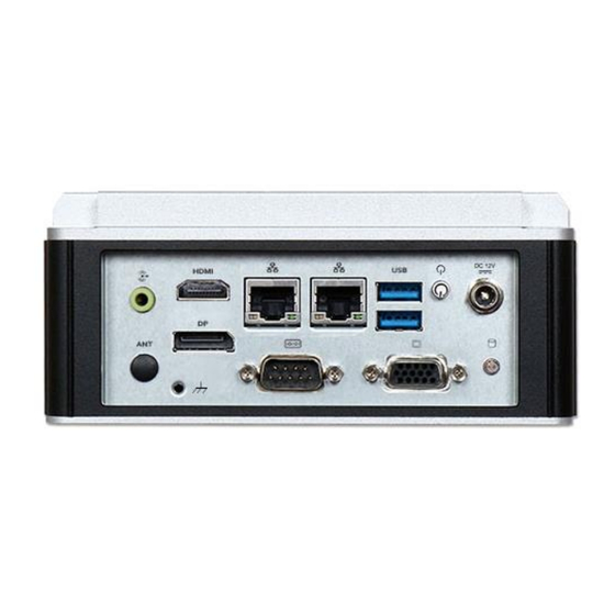
1.4 Mechanical Dimension Front view of the WEBS-21I0 system (standard) Front view of the WEBS-21I0 system (with optional kit: addition 2x USB 3.0) Front view of the WEBS-21I0 system (with optional kit: DIN-Rail mounting) Rear view of the WEBS-21I0 system... - Page 7 System Overview Side view of the WEBS-21I0 system Top view of the WEBS-21I0 system WEB-21I0 User’s Manual...
-
Page 8: Chapter 2 System Installation
System Installation Chapter 2 System Installation This chapter provides you with instructions to set up your system. Definitions and locations of all the interfaces are described so that you can easily configure your system. For more detailed PIN assignment and jumper setting, please refer to user’s manual of NANO-6063. -
Page 9: Key E 2230 Device Installation
System Installation 2.2 M.2 Key E 2230 Device Installation It’s easy to install and maintenance the 1x M.2 2230 device by just open the back cover. Step 1. Loosen the 4 screws of the back Step 2. Take out the back cover cover Step 3. -
Page 10: Din Rail Mounting Device Installation
System Installation 2.3 DIN Rail Mounting Device Installation It’s easy to install and maintenance the Din Rail mounting device by just open the back cover. Step 1. Loosen the 4 screws of the back Step 2. Take out the back cover cover Step 3. -
Page 11: Getting Started
System Installation 2.4 Getting Started It is easy to get the system started. Step 1. Make sure the power supply Step 2. Press the power button to turn (12V) is connected properly on the system WEB-21I0 User’s Manual... -
Page 12: I/O Interfaces
System Installation 2.5 I/O Interfaces 2.5.1 Front View (Standard) 2.5.2 Front View (Optional Kit: Additional 2x USB 3.0) 2.5.3 Rear View WEB-21I0 User’s Manual... - Page 13 System Installation DC in: (12V) Using the provided DC source to connect to the system Power Button: Press the power button to turn ON/OFF the system SSD LED: Shows real-time read and write activity of your SSD as a small blinking indicator DP / VGA / HDMI: DP / VGA /HDMI (Display Port) display output LAN:...
-
Page 14: Chapter 3 Bios Setup Information
BIOS Setup Information Chapter 3 BIOS Setup Information WEBS-21I0 system adopts NANO-6063 mother board. The following section describes the BIOS setup program. The BIOS setup program can be used to view and change the BIOS settings for the module. Only experienced users should change the default BIOS settings. -
Page 15: Main
BIOS Setup Information 3.2 Main Use this menu for basic system configurations, such as time, date etc. Feature Description Options The date format is <Day>, <Month> <Date> <Year>. System Date Use [+] or [-] to configure system Date. The time format is <Hour> <Minute> <Second>. Use System Time [+] or [-] to configure system Time. -
Page 16: Configuration
BIOS Setup Information 3.3 Configuration CPU Configuration WEB-21I0 User’s Manual... -
Page 17: Boot
BIOS Setup Information Feature Description Options ★Disabled, Enable/Disable CPU Flex Ratio CPU Flex Ratio Programming Enabled Override CPU Flex Ratio This value must be between Max Efficiency ★20 Settings Ratio (LFM) and Maximum non-turbo ratio set by Hardware (HFM). When enabled, a VMM can utilize the Intel (VMX) ★Enabled, Virtualization... - Page 18 BIOS Setup Information Chipset Configuration Configuration Chipset feature Feature Description Options ★Enabled, VT-d VT-d Capability Disabled Enable/Disable above 4GB Memory Mapped Above 4GB ★Enabled, IO BIOS assignment. MMIO BIOS This is enabled automatically when Aperture Disabled assignment Size is set to 2048MB Control Detection of the HD-Audio device.
- Page 19 BIOS Setup Information Graphics Configuration Configuration Graphics Settings Feature Description Options Keep IGFX enable based on the ★Auto, Disable, Enable Internal Graphics setup options. WEB-21I0 User’s Manual...
- Page 20 BIOS Setup Information Power Control Configuration System Power Control Configuration Parameters Feature Description Options Enables or Disables System ability Enable to Hibernate (OS/S4 Sleep State). ★Enabled, Disabled Hibernation This option may be not effective with some operating systems. ★S3 (Suspend to Select the highest ACPI sleep state ACPI Sleep State the system will enter when the...
- Page 21 BIOS Setup Information PCI/PCIE Configuration PCI Express Root Port Settings. Feature Description Options Enables when using Enable Hibernation ★ Disabled, Enabled Compliance Load Board. WEB-21I0 User’s Manual...
- Page 22 BIOS Setup Information Feature Description Options Control the PCI Express Root ★Enabled, Disabled COMe PCIe Port Port. Built-In: a built-in device is connected to this root port. Slot Implemented bit will be clear. ★Slot, Built-in Connection Type Slot: this root port connects to user-accessible slot.
- Page 23 BIOS Setup Information ★Enabled, Disabled Enable/Disable Downstream Port Containment Enable/Disable Root port ★Enabled, Disabled EDPC extensions for Downstream Port Containment PCI Express Unsupported ★Disabled, Enabled Request Reporting Enable/Disable. ★Disabled, Enabled PCI Express Device Fatal Error Reporting Enable/Disable PCI Express Device Non-Fatal ★Disabled, Enabled NFER Error Reporting...
- Page 24 BIOS Setup Information (4K/8K/12K/16K/20K) Range for this Root Bridge. ★Enabled, Disabled PCH PCIE Latency Reporting Enable/Disable Snoop Latency Override for PCH PCIE. Disabled: Disable override. Snoop Latency ★Auto, Manual, Disabled Override Manual: Manually enter override values. Auto (default): Maintain default BIOS flow. ★60 Snoop Latency Value LTR Snoop Latency value of PCH PCIE...
- Page 25 BIOS Setup Information Extra options Feature Description Options Detect Non-Compliance Detect Non- PCI Express Device. If ★Disabled, Enabled Compliance Device enable, it will take more time at POST time. Prefetchable Prefetchable Memory Range for this Root Bridge. ★10 Memory Reserved Memory Reserved Memory ★1 Alignment...
- Page 26 BIOS Setup Information LAN Configuration Configuration on Board LAN device. Feature Description Options Intel PSE TSN GbE #0 (SGMII Mode) ★ Host owned with pin Select ownership for GBE PSE TSN GBE 0 muxed, SPE owned with pin muxed, None ★SGMII 1 PSE TSN GBE 0 Link Speed PSE TSN GBE 0 Link...
- Page 27 BIOS Setup Information ★Enabled, Controller USB Port Power Enabled or USB Port 2/3 Power Disabled Disabled Network stack (Enable) Enable /Disable IPv4 PXE Support. If ★Enabled, Ipv4 PXE Support disable, IPv4 PXE boot support will not Disabled be available. ★Enabled, Enable /Disable Ipv4 HTTP Support.
- Page 28 BIOS Setup Information SATA Configuration SATA Device Options Settings Feature Description Options Serial ATA Port 0 ★Enabled, Port 0 Enable or Disable SATA Port Disabled ★Disabled, Hot Plug Designates this port as Hot Pluggable Enabled ★Hard Disk Identify the SATA port is connected SATA Device Type to Solid State Drive or Hard Disk Drive, Solid State...
- Page 29 BIOS Setup Information USB Configuration USB Configuration Parameters Feature Description Options This is a workaround for OSes without XHCI hand- ★Enabled, XHCI Hand- off support. The XHCI ownership change should be Disabled claimed by XHCI driver USB Mass ★Enabled, Storage Enable/Disable USB Mass Storage Driver Support Driver Disabled...
- Page 30 BIOS Setup Information up delay properly reports itself to the Host Controller. Manual ‘Auto’ uses default value: for a Root port it is 100 ms, for a Hub port the delay is taken from Hub descriptor. Device power-up delay -- ★Manual Device power- ★5 Delay range is 1..40 seconds, in one second...
- Page 31 BIOS Setup Information ★Disabled, SHA-1 PCR Enables or Disables SHA-1 PCR Bank Bank Enabled ★Enabled, SHA256 PCR Enables or Disables SHA256 PCR Bank Bank Disabled Schedule an Operation for the Security ★None, TPM Device. Note: Your Computer will reboot Pending operation during restart in order to change State of Clear...
- Page 32 BIOS Setup Information Super IO Configuration System Super IO Chip Parameters. Feature Description Options ★Enabled, Module Serial Enable or Disable Serial Port (COM) Port 1 Disabled ★RS-232,RS-484 RS-232/422/485 Serial Port 3 RS-232/422/485 Control Option HALF DUPLEX, Control Option RS-422 FULL DUPLEX, ★Disabled, Watch Dog...
- Page 33 BIOS Setup Information H/W Monitor Monitor hardware status Serial Port Console Redirection Serial Port Console Redirection Feature Description Options ★Disabled, Enabled COM0 Console Redirection Console Redirection Enable or Disable WEB-21I0 User’s Manual 3-20...
- Page 34 BIOS Setup Information COM0 Console Redirection Settings Feature Description Options Emulation: ANSI: Extended ASCII char set. ★ANSI, VT100, VT100: ASCII char set. VT100+: Extends Terminal Type VT100 to support color, function keys, etc. VT100+, VT- VT-UTF8: Uses UTF8 encoding to map UTF8 Unicode chars onto 1 or more bytes.
- Page 35 BIOS Setup Information Communication with slow devices may require more than 1 stop bit. Flow control can prevent data loss from buffer overflow. When sending data, if the ★None, receiving buffers are full, a ‘stop’ signal can Flow Control be sent to stop the data flow. Once the buffers Hardware are empty, a ‘start’...
- Page 36 BIOS Setup Information EC Firmware Update Feature Description Options Select File Select ROM image Bin file to the USB DOK WEB-21I0 User’s Manual 3-23...
- Page 37 BIOS Setup Information Update EC WEB-21I0 User’s Manual 3-24...
- Page 38 BIOS Setup Information 3.4 Security This section lets you set security passwords to control access to the system at boot time and/or when entering the BIOS setup program. Feature Description Options [Setup] check password when enter ★Setup, Power setup screen. [Power on] check Password Check Mode password on every time system power on.
- Page 39 BIOS Setup Information 3.5 Boot Use this menu to specify the priority of boot devices. Feature Description Options Set the default timeout before system Setup Prompt ★1 boot. A value of 65535 will disable the Timeout timeout completely. Bootup ★On, Off Select the keyboard NumLock state NumLock State ★Disabled,...
-
Page 40: Save & Exit
BIOS Setup Information UEFI Application Boot Priorities: 3.6 Save & Exit WEB-21I0 User’s Manual 3-27... - Page 41 BIOS Setup Information Feature Description Options Reset the system after saving Save Changes and Reset the changes. Reset system setup without Discard Changes and Reset saving any changes. Restore/Load Default values Restore Defaults for all the setup options. Reset the system after saving the changes.
- Page 42 BIOS Setup Information Step 4. Plug the USB DOK into the target system and boot from UEFI Shell. Step 5. Under the UEFI shell, direct to your USB DOK, below is an example uses fs0. Then direct to the folder with updated file and type command: "update" and press enter.
- Page 43 BIOS Setup Information (EC File Update) Step 6. The updating process will start and you can see the updating progress. Once finished, please power off and restart the system. (BIOS updating progress) WEB-21I0 User’s Manual 3-30...
- Page 44 BIOS Setup Information (EC updating progress) WEB-21I0 User’s Manual 3-31...
-
Page 45: Chapter 4 Important Instructions
In the event of damage to the system unit caused by failure to abide by the hints in this manual and on the unit (especially the safety instructions), Portwell, Inc. shall not be required to respect the warranty even during the warranty period and shall be free from the statutory accident liability obligation. -
Page 46: Chapter 5 Frequent Asked Question
Frequent Asked Question Chapter 5 Frequent asked question Question 1: I forgot my password of system BIOS, what am I supposed to do? Answer: You can switch off your power supply then find the JP3 on the NANO-6063 board to set it from 2-3 n/a to 1-2 short and wait 5 seconds to clean your password then set it back to 2-3 short to switch on your power supply. - Page 47 Frequent Asked Question Question 3: Portwell Software Service? Answer: 1. 1. If you have customized requirements of BIOS, you can contact person of our company or branch. 2. 2. If you have requirements of WDT、GPIO APP, you can contact our headquarter or branch, and we can render your assistance on developing.
Need help?
Do you have a question about the WEBS-21I0 and is the answer not in the manual?
Questions and answers