
Related Manuals for Portwell WEBS-85H2


Summary of Contents for Portwell WEBS-85H2
- Page 1 WEBS-85H2 IPC System AS5-3632 User's Manual Version 1.3 Copyright © Portwell, Inc., 2022. All rights reserved. All other brand names are registered trademarks of their respective owners.
-
Page 2: Table Of Contents
4.1 Note on the Warranty ..................4-1 4.2 Exclusion of Accident Liability Obligation ........... 4-1 4.3 Liability Limitations / Exemption from the Warranty Obligation.... 4-1 4.4 Declaration of Conformity ................4-1 Chapter 5 Frequent Asked Questions ..................5-1 Portwell Software Service ......................5-3... -
Page 3: How To Use This Manual
Preface How to Use This Manual The manual describes how to configure your WEBS-85H2 system to meet various operating requirements. It is divided into four chapters, with each chapter addressing a basic concept and operation of Embedded System. Chapter 1: System Overview. Present what you have in the box and give you an overview of the product specifications and basic system architecture. -
Page 4: Chapter 1 System Overview
DDR4 memory. Type II CFast and 2x 2.5” SSD slots for storage. Support three Gigabit Ethernet ports, One M.2 E Key, One M.2 M Key and one Mini PCIe socket. The WEBS-85H2 is an ideal platform with rich I/O and high resolution for POS, kiosk, digital signage, and factory automation applications. -
Page 5: Product Specification
System Overview 1.3 Product Specification System Proprietary System Chipset Intel W480E chipset ® 10th Generation Intel® Core™ i3/i5/i7/i9 Processors BIOS AMI uEFI BIOS (SPI ROM) System Memory 2x SO-DIMM sockets support DDR4 2400/2666 Non-ECC Up to 64 GB Storage - 1x Type II CFast slot - 2x 2.5”... -
Page 6: Mechanical Dimension
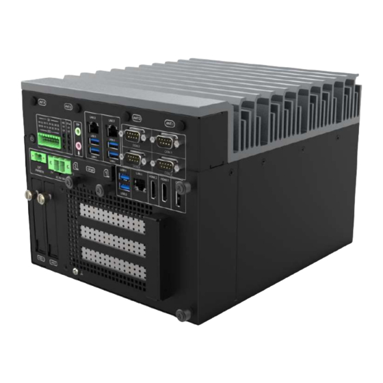
System Overview 1.4 Mechanical Dimension Front view of the WEBS-85H2 system Rear view of the WEBS-85H2 system Top view of the WEBS-85H2 system WEB-85H2 User’s Manual... -
Page 7: Chapter 2 System Installation
System Installation Chapter 2 System Installation This chapter provides you with instructions to set up your system. Definitions and locations of all the interfaces are described so that you can easily configure your system. Important: Turn off the power of your IPC BOX PC and allow it to cool for at least 10 ◼... -
Page 8: M/B Jumper Setting
System Installation 2.1.2 M/B Jumper setting Detail information Part Description M.2 module (M-key, type 2242/2260/2280) M.2 M-key slot or M.2 B+M key TPU module The SPI TPM header supports a TPM system. SPI TPM header The Chassis Intrusion header allows you to connect an intrusion sensor or microswitch for the chassis intrusion detection feature. - Page 9 System Installation The Mini PCIe / mSATA switch jumper allows you to set the Mini PCIe /mSATA slot to either support a Mini PCIe card or Mini PCIe / mSATA card. Default is SATA mode. mSATA switch jumper The CAN / COM switch jumpers allows you to set COM4 to CAN bus or COM port.
-
Page 10: Cpu And Memory Module Installation
System Installation 2.2 CPU and Memory module Installation Equipped with CPU and Memory module by yourself if you purchase CPU or Memory module locally. Step 1. Loosen the screws of top Step 2. Check system inside heatsink (there are 6 screws) Step 3. - Page 11 System Installation Step 5. Install CPU. Please locate Step 6. Install CPU successfully notches on both side and pin one of CPU first Step 7. Make sure the thermal paste Step 8. Fixed the screws of top heatsink can be applied uniformly on the heat (there are 6 screws) spreader.
- Page 12 System Installation Step 3. Push the side cover towards Step 4. Install DDR4 so DIMM Memory the rear of the system. Module on the system Step 5. Make sure Memory module Step 6. Push the side cover towards the are installation successfully rear of the system.
-
Page 13: Hdd Installation
System Installation 2.3 HDD Installation Unique design of the HDD tray allows easy installation and maintenance of 2.5” HDD/SSD. RAID function is supported with dual HDD/SSD design. (The height must be less than 10mm) Step 1. Loosen the thumbscrews of the Step 2. -
Page 14: Desk Mount Installation
System Installation 2.4 Desk mount Installation Step 1. Prepare Desk mount kit and Step 2. System is ready for assembling. screws. 1. Screw size (M3x4L): for system side. 2. Screw size (Support M3x6L and M4 x 8L): for Desk mount side Step 3. -
Page 15: I/O Interfaces
System Installation 2.5 I/O Interfaces Front View Function Photo Description ANT1.ANT4 Antenna holes for LTE module ANT2.ANT3 Antenna holes for WIFI module Power Press the power button to turn ON/OFF the button system DI/DO The Isolation Digital Input / Output WD LED: Watchdog LED: LED color is Green. - Page 16 System Installation Audio Audio Jack for Mic-In, Line-In and Line-Out Two Gigabit Ethernet (10/100/1000 Mbits/sec) LAN ports by using Intel I210-IT GbE Ethernet ® ContN NNroller Support six USB (Universal Serial Bus) ports, four USB 3.2 Gen1 and two USB 3.2 Gen 2. Support 4x COM ports, COM1~COM3 default is RS-232, COM4 default is RS-232 (1x RS-232/422/485,...
-
Page 17: Getting Started
System Installation CFast Support 1x CFast card slot HDMI1 HDMI 1.4 display output HDMI2 HDMI 2.0 display output DP (Display Port) 1.2 display output Two removable 2.5" SSD trays for storage installation Expansion 3x PCIe Expansion Slot option slot (1x PCIe x16 + 1x PCIe x4 or 2x PCIe x8 + 1x PCIe x4 (auto-detect)) -If customer chooses to add graphic card, AI accelerator or high-power consumption card,... -
Page 18: Chapter 3 Bios Setup Information
System Installation Chapter 3 BIOS Setup Information The following section describes the BIOS setup program. The BIOS setup program can be used to view and change the BIOS settings for the module. Only experienced users should change the default BIOS settings. 3.1 Entering Setup Power on the computer and the system will start POST (Power on Self Test) process. -
Page 19: Main
System Installation 3.2 Main 3.2.1 Main Use this menu for basic system configurations, such as time, date etc. Feature Description Options The date format is <Day>, <Month> <Date> <Year>. Use [+] or [-] System Date to configure system Date. The time format is <Hour> <Minute> <Second>. Use [+] or [-] to System Time configure system Time. -
Page 20: Configuration
System Installation 3.3 Configuration 3.3.1 PCH-FW Configuration Configure Management Engine Technology Parameters Feature Description Options Selects TPM device: PTT or dTPM. PTT-Enable TPM Device PTT in SkuMgr dTPM1.2 –Disables PTT in SkuMgr ★dTPM , PTT Selection Warning! PTT/dTPM will be disabled and all data saved on it will be lost. - Page 21 System Installation 3.3.2 CPU Configuration CPU Configuration Parameters Feature Description Options Intel (VMX) When enabled, a VMM can utilize the additional ★Enabled, Virtualization hardware capabilities provided by Vanderpool Disabled Technology Technology. ★Enabled, Hyper-Threading Enable or Disable Hyper-Threading Technology. Disabled Enables utilization of additional hardware ★Disabled, Intel Trusted capabilities provided by Intel(R) Trusted Execution...
- Page 22 System Installation CPU- Power Management Control CPU- Power Management Control Options Feature Description Options ★Enabled, Intel(R) Allows more than two frequency ranges to be SpeedStep(tm) supported. Disabled Enable/Disable Intel(R) Speed Shift Technology ★Enabled, Intel(R) Speed Shift support. Enabling will expose the CPPC v2 interface to Technology Disabled allow for hardware-controlled P-states.
- Page 23 System Installation 3.3.3 Graphics Configuration System Agent (SA)Parameters Feature Description Options Select which of IGFX/PEG/PCIE Graphics ★Auto, IGFX,PCIE,PEG Primary Display device should be Primary Display. ★Auto,Disabled ,Enabl Internal Graphics Keep IGFX enabled based on the setup options. RC6 (Render ★Enabled, Disabled Check to enable render standby support.
- Page 24 System Installation 3.3.4 PCI Express Configuration PCI Express Configuration Feature Description Options PCIE x4 slot PCI Express Root Port Settings. PCIE x16/x8 Slot PCIE x16/x8 Slot Options PCIE x4_slot Feature Description Options ★Enabled, Disabled PCIE x4 slot Control the PCI Express Root Port. Set the ASPM Level: ★Disabled, L0s, L1, Force L0s –...
- Page 25 System Installation PCIE x16/x8 Slot 3.3.5 PEG Port Configuration Feature Description Options PEG 0:1:0 (PCIE x16/x8_1) Enable Root ★Auto, Disabled, Enabled Enable or Disable the Root Port Port Max Link ★Auto, Gen1, Gen2, Gen3 Configure PEG 0:1:0 Max Speed Speed ★Auto, Force x1, Force x2, Max Link Force PEG link to retrain to x1/2/4/8...
- Page 26 System Installation 3.3.6AMT Configuration Configure Intel(R) Active Management Technology Parameters Feature Description Options ★Disabled, USB Provisioning Enable/Disable of AMT USB Provisioning. of AMT Enable CIRA Configure Remote Assistance Process parameters. Configuration OEM Flags Configure OEM Flags Settings MEBx Resolution Resolution settings for MEBx display modes. Settings 3.3.7 CIRA Configuration Feature...
- Page 27 System Installation OEM Flags Settings Feature Description Options ★Disabled, OEMFLag Bit 1: MEBx hotkey Pressed Enable automatic MEBx hotkey press. Enable OEMFLag Bit 2: Enable MEBx selection screen with 2 options: Press 1 to enter ME Configuration Screens ★Disabled, MEBx Selection Press 2 to initiate a remote connection Screen Enable...
- Page 28 System Installation MEBx Resolution Settings Feature Description Options ★Auto, 80x25, Non-UI Mode Resolution for non-UI text mode. Resolution 100x31 ★Auto, 80x25, UI Mode Resolution Resolution for UI text mode. 100x31 ★Auto, Graphics Mode 640x480, Resolution for graphics mode. Resolution 800x600, 1024x768 WEB-85H2 User’s Manual 3-22...
- Page 29 System Installation 3.3.8 CSM Configuration CSM Configuration: Enable/Disable, Option ROM execution settings, etc. Feature Description Options ★Disable, CSM Support Enable/Disable CSM Support Enabled CSM Support [Enable] ★Do not launch, Controls the execution of UEFI and Legacy Network Network OpROM. UEFI, Legacy ★UEFI, Do not Controls the execution of UEFI and Legacy Storage...
- Page 30 System Installation 3.3.9 Super IO Configuration Super IO Configuration Feature Description Options Serial Port 1 Set Parameters of Serial Port1(COMA) Configuration Serial Port 2 Set Parameters of Serial Port2(COMB) Configuration Serial Port 3 Set Parameters of Serial Port3(COMC) Configuration Serial Port 4 Set Parameters of Serial Port4(COMD) Configuration WEB-85H2 User’s Manual...
- Page 31 System Installation 3.3.10 Serial Configuration Serial Port 1 Configuration ◼ Feature Description Options ★Enabled, Serial Port Enable or Disable Serial Port (COM) Disabled ★RS232,RS422, COM1 Control Select COM1 mode. RS232, RS422 or RS485 RS485 ◼ Serial Port 2 Configuration Feature Description Options ★Enabled,...
- Page 32 System Installation ◼ Serial Port 3 Configuration Feature Description Options ★Enabled, Serial Port Enable or Disable Serial Port (COM) Disabled ★RS232,RS422, COM3 Control Select COM3 mode, RS232, RS422 or RS485 RS485 Serial Port 4 Configuration ◼ Feature Description Options ★Enabled, Serial Port Enable or Disable Serial Port (COM) Disabled...
- Page 33 System Installation Serial Console Redirection Serial Console Redirection Feature Description Options ★Disabled, Console Redirection Console Redirection Enable or Disable Enabled Console Redirection [Enabled] The settings specify how the host computer and the remote computer (which the user is Console Redirection Settings using) will exchange data.
- Page 34 System Installation Console Redirection Settings Feature Description Options Emulation: ANSI: Extended ASCII char set. VT100: ASCII char set. VT100+: Extends VT100 to support ★ANSI, VT100, Terminal Type color, function keys, etc. VT-UTF8: Uses UTF8 VT100+, VT-UTF8 encoding to map Unicode chars onto 1 or more bytes.
- Page 35 System Installation Legacy Console Redirection Settings Feature Description Options ★COM1,COM2,COM3,C Redirection Select s COM port to display redirection of Legacy COM Port OS and Legacy OPROM Messages. On Legacy OS, the number of Rows and Columns ★80X24,80X25 Resolution supported redirection. When Bootloader is selected, then Legacy Console Redirection is disabled before booting to legacy ★Always...
- Page 36 System Installation 3.3.11 SATA And RST Configuration SATA Device Options Settings Feature Description Options Enable/disable the SATA ★Enabled , Disabled SATA Controller(s) controllers. ★AHCI, Intel RST Determines how SATA SATA Mode Selection controller(s) operate. Premium(RAID) Test Mode Enable/Disable (Loop ★Disabled, Enabled SATA Test Mode Back) ★Enabled, Disabled...
- Page 37 System Installation 3.3.12 Network Stack Configuration Network Stack Settings Feature Description Options ★Disabled, Enabled Network Stack Enable/ Disable UEFI Network Stack Network Stack [Enabled] Enable/Disable IPv4 PXE boot support. If ★Disabled, Enabled Ipv4 PXE Support disable, IPv4 PXE boot support will not be available.
- Page 38 System Installation 3.3.13 USB Configuration USB Configuration Parameters Feature Description Options Enables Legacy USB support. AUTO option ★Enabled, disables legacy support if no USB devices are Legacy USB Support connected. DISABLE option will keep USB devices Disabled, Auto available only for EFI applications. This is a workaround for OSes without XHCI hand- ★Enabled, XHCI Hand-off...
- Page 39 System Installation 3.3.14 NVMe Configuration NVMe Device Option Settings WEB-85H2 User’s Manual 3-33...
- Page 40 System Installation 3.3.15 Onboard Devices Configuration Onboard Devices Options Settings Feature Description Options Control Detection of the HD-Audio device. ★Enabled, Disabled HD Audio Disabled= HDA will be unconditionally disabled. Enabled= HDA will be unconditionally enabled. ★Enabled, Disabled LAN1 I210IT Enable/Disable LAN1 I210IT Intel LAN1 ★Disabled, Enabled Launch Intel PXE OPROM.
- Page 41 System Installation Enables/Disables Serial Io Controller If given device is Function 0PSF disabling is skipped. PSF default will remain and device PCI CFG ★Disabled, Enabled SPI0 Controller Space will still be visible. This is needed to allow PCI enumerator access functions above 0 in a multifunction device.
- Page 42 System Installation Watchdog Timer Feature Description Options ★Enable, Disabled Watchdog Support Enable/Disable Watchdog Support. ★Second Mode, Watchdog Count mode Select Watchdog Timer I count mode. Minute Mode ★60 Watchdog Timer Watchdog Timer I Time-out value. WEB-85H2 User’s Manual 3-36...
- Page 43 System Installation Miscellaneous Feature Description Options DMI/OPI Configuration Enable/Disable the control of Active ★Disabled, DMI Link ASPM L0s, State Power Management on SA side of Control L0sL1 the DMI Link. PCI Express Configuration ★Disabled, DMI Link ASPM The control of Active State Power L0s, Control Management of the DMI Link.
- Page 44 System Installation Smart Fan Function Smart Fan Function setting Feature Description Options System Fan Setting ★55 Temperature 1 The value of temperature 1. ★75 Temperature 2 The value of temperature 2. ★85 Temperature 3 The value of temperature 3. ★95 Temperature 4 The value of temperature 4.
-
Page 45: Security
System Installation 3.4 Security Feature Description Options Administrator Password Set Administrator password. User Password Set User Password Secure Boot Secure Boot configuration Feature Description Options Secure Boot feature is Active if Secure Boot is ★Disabled, Enabled, Platform Key (PK) is enrolled and the Secure Boot System is in User mode. - Page 46 System Installation Key Management Feature Description Options Enroll Factory Defaults or load certificates from Platform Key(PK) a file: Key Exchange Keys 1.Publuc Key Certificate: Authorized Signatures a)EFI_SIGNATURE_LIST b) EFI_CERT_X509 (DER) c) EFI_CERT_RSA2048 (bin) d)EFI_CERT_SHAXXX Forbidden Signatures 2.Authenticated UEFI Variable 3.EFI PE/COFF Image(SHA256) Key Source: Factory, External, Mixed HDD Security Configuration WEB-85H2 User’s Manual...
-
Page 47: Boot
System Installation 3.5 Boot Feature Description Options ★Disabled, CHASSIS INTRUDE Enable/Disable CHASSIS INTRUDE Enabled Number of seconds to wait for setup ★1 Setup Prompt Timeout activation key. 65535(0xFFFF) means indefinite waiting. ★On, Off Bootup NumLock State Select the keyboard NumLock state ★Disabled, Quiet Boot Enables or disables Quiet Boot option... - Page 48 System Installation UEFI Hard Disk Drive BBS Priorities WEB-85H2 User’s Manual 3-42...
-
Page 49: Save & Exit
System Installation 3.6 Save & Exit Feature Description Options Save Changes and Exit Exit system setup after saving the changes. Discard Changes and Exit Exit system setup without saving any changes. Save Changes and Reset Reset the system after saving the changes. Discard Changes and Reset Rest system setup without saving any changes. -
Page 50: Chapter 4 Important Instructions
4.2 Exclusion of Accident Liability Obligation Portwell, Inc. shall be exempt from the statutory accident liability obligation if users fail to abide by the safety instructions. 4.3 Liability Limitations / Exemption from the Warranty Obligation In the event of damage to the system unit caused by failure to abide by the hints in this manual and on the unit (especially the safety instructions), Portwell, Inc. -
Page 51: Chapter 5 Frequent Asked Questions
Chapter 5 Frequent Asked Questions Question: How to update the BIOS file of WEBS-85Hx? Answer: 1. Please visit web site of Portwell download center as below hyperlink https://www.portwell.com.tw/support-center/download-center/ 2. Select “Search download” and type the keyword “WEBS-85H”. 3. Find the “BIOS “page and download the ROM file and unzip file to USB flash drive (FAT 32 / 16 format). - Page 52 5. Enter EZ-Flash mode, Select the USB Drive and Click the BIOS file then start updating BIOS. 6.When you see the “BIOS updated successfully” message, which means the BIOS update processes finished. Please cut the AC power of and wait for 10 seconds before powering on.
-
Page 53: Portwell Software Service
We will do our best to provide a suggestion or solution for you. Portwell Software Service 1. If you have customized requirements of BIOS, you can contact person of our company or branch. 2. If you have requirements of WDT、GPIO APP, you can contact our headquarter or branch, and we can render your assistance on developing.
Need help?
Do you have a question about the WEBS-85H2 and is the answer not in the manual?
Questions and answers