
Related Manuals for Portwell WADE-8065


Summary of Contents for Portwell WADE-8065
- Page 1 WADE-8065 Mini-ITX Board User's Manual Version 1.0 Copyright © Portwell, Inc., 2008. All rights reserved. All other brand names are registered trademarks of their respective owners.
-
Page 2: Table Of Contents
Preface Table of Contents How to Use This Manual Chapter 1 System Overview.......................1-1 1.1 Introduction..........................1-1 1.2 Check List ............................. 1-1 1.3 Product Specification ........................1-2 1.3.1 Mechanical Drawing......................1-4 1.4 System Architecture ........................1-6 Chapter 2 Hardware Configuration ...................2-1 2.1 Jumper Setting .......................... -
Page 3: How To Use This Manual
Preface How to Use This Manual The manual describes how to configure your WADE-8065 system board to meet various operating requirements. It is divided into five chapters, with each chapter addressing a basic concept and operation of Single Host Board. -
Page 4: Chapter 1 System Overview
WADE-8065 is a network bandwidth-enriched solution. With a low power consumption mobile processor, it not only provides more than adequate computing power but also eliminates any heat issues. Dual video outputs are supported by two-channel memory structure that enhances graphic performance. -
Page 5: Product Specification
- Intel 945GME GMCH integrated GMA 950 Graphic device - Intel DVMT3.0 supports up to 224MB video memory On-board Ethernet LAN Three Gigabit Ethernet (10/100/1000 Mbits/sec) LAN ports using Intel 82574L PCI-Expressx1interface GbE Ethernet Controller High Drive GPIO On-board programmable 8-bit Digital I/O interface WADE-8065 User’s Manual... - Page 6 170mm(6.69’’) x 170mm(6.69’’) Power Requirements Configuration CPU Type Intel® Core™ 2 1.99GHz T7200 (166*12) L2:4096K FSB:667MHz SBC BIOS Portwell,Inc. WADE-8065 BIOS Rev.:R1.00.W0 (09102008) Memory Transcend DDR2 800 512MB (SAMSUNG K4T51083QE )*2 VGA Card Onboard Mobile Intel® 945 Express Chipset Family VGA Driver Mobile Intel®...
-
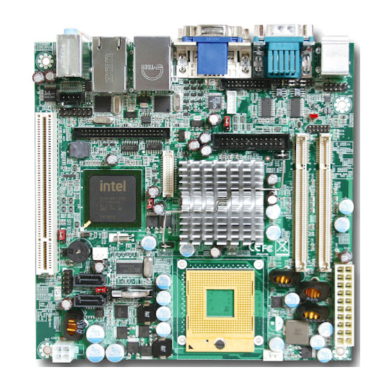
Page 7: Mechanical Drawing
System Overview Operating Temperature 0 °C ~ 60 °C Storage temperature -20 ~ 80 °C Relative Humidity 0% ~ 90%, non-condensing 1.3.1 Mechanical Drawing WADE-8065 User’s Manual... - Page 8 System Overview WADE-8065 User’s Manual...
-
Page 9: System Architecture
System Overview System Architecture All of details operating relations are shown in WADE-8065 System Block Diagram. WADE-8065 System Block Diagram WADE-8065 User’s Manual... -
Page 10: Chapter 2 Hardware Configuration
Hardware Configuration This chapter gives the definitions and shows the positions of jumpers, headers and connector. All of the configuration jumpers on WADE-8065 are in the proper position. The default settings are indicated with a star sign ( ). Jumper Setting In the following sections, Short means covering a jumper cap over jumper pins;... - Page 11 3.3V 2-3 Short JP3 : LVDS Power Function 1-2 Short 3.3V 2-3 Short JP5 : SPI BIOS Function 1-2 Short Write Protect JP6 : Clear CMOS Function 1-2 Short Normal 2-3 Short Clear WADE-8065 User’s Manual...
-
Page 12: Connector Allocation
LVDS Connector PCI Slot DDR2 SODIMM 0 DDR2 SODIMM 1 System FAN (3-pin Smart FAN) SATA1 Connector USB 2,3 Pin Header Battery Connector SATA2 Connector ATX Power Connector Power 12V Connector CPU FAN (4-pin Smart FAN) CF Connector WADE-8065 User’s Manual... - Page 13 Signal Description PIN No. Signal Description 5V Dual 5V Dual USB- USB- USB+ USB+ Ground Ground Ground TPM 1.2 Header PIN No. Signal Description PIN No. Signal Description Frame Reset LAD3 LAD2 VCC3 LAD1 LAD0 3VSB Serirq SUS_LED WADE-8065 User’s Manual...
- Page 14 LVDSB_DATA1 LVDSB_DATA#1 LVDSB_DATA2 LVDSB_DATA#2 LVDSB_CLKP LVDSB_CLKN DDC_DATA DDC_CLK Back light control LVDS Inverter Power PIN No. Signal Description Backlight_enable VCC12 J11 Header PIN No. Signal Description PIN No. Signal Description 5VSB HD_LED SYS_Reset SUS_LED Power Bottom Speaker WADE-8065 User’s Manual...
- Page 15 Hardware Configuration GPIO Header PIN No. Signal Description PIN No. Signal Description GPIO0 GPIO5 GPIO1 GPIO6 GPIO2 GPIO7 GPIO3 GPIO8 VCC12 WADE-8065 User’s Manual...
-
Page 16: Chapter 3 System Installation
PCI device, handle Watch Dog Timer (WDT) and operation of GPIO in software programming. ® Intel mPGA 478MN CPU Installing Intel mPGA478MN CPU 1) Make sure to loosen the latch of actuator at correctly position (Open), WADE-8065 User’s Manual... - Page 17 2) Unlock the latch of CPU socket to open position. 3) Carefully lifts up the existing CPU to remove it from the socket. 4) Follow the steps of installing a CPU to change to another one or place handling bar to close the opened socket. WADE-8065 User’s Manual...
-
Page 18: Main Memory
System Installation Configuring System Bus WADE-8065 will automatically detect the CPU FSB 533/667 MHz used. CPU speed of Intel Core 2 Duo Processor for Mobile, Core duo and Celeron M can be detected automatically. Main Memory WADE-8065 provides 2 x 200-pin SO-DIMM sockets which supports 667/533 MHz DDR2-SDRAM as main memory, Non-ECC (Error Checking and Correcting), non-register functions. -
Page 19: Installing The Single Board Computer
3.3.1 Chipset Component Driver The chipset on WADE-8065 is a new chipset that a few old operating systems might not be able to recognize. To overcome this compatibility issue, for Windows Operating Systems such as Windows 2000 /XP / VISTA, please install INF before any of other Drivers are installed. -
Page 20: Intel Gigabit Ethernet Controller
3.3.3 Intel Gigabit Ethernet Controller Drivers Support Please find Intel 82573L LAN (J5 & J6) driver in /Ethernet directory of WADE-8065 CD-title. The drivers support Windows 2000 /XP / VISTA. LED Indicator (for LAN status) WADE-8065 provides two LED indicators to report Intel 82574L Gigabit Ethernet interface status. -
Page 21: Wdt Function
WADE-8065 allows users control WDT through dynamic software programming. The WDT starts counting when it is activated. It sends out a signal to system reset, when time-out interval ends. -
Page 22: Gpio
2) 0x01~0xFF -- Value for counting down GPIO WADE-8065 provides 8 programmable input or output ports that can be individually configured to perform a simple basic I/O function. Users can configure each individual port to become an input or output port by programming register bit of I/O Selection. - Page 23 (0V/5V), and each source sink capacity up to 12mA. WADE-8065 GPIO Programming Guide There are 8 GPIO pins on WADE-8065. These GPIO pins are from SUPER I/O (W83627THF) GPIO pins, and can be programmed as Input or Output direction. J18 pin header is for 8 GPIO pins and its pin assignment as following : J18_Pin3=GPIO0:from SUPER I/O_GP10 with Ext.
- Page 24 Read LD7_CRF1h_Bit0; Read the status from GPIO10 pin (J18_Pin3) How to access W83627THF CR? In WADE-8065, the EFER = 002Eh, and EFDR = 002Fh. EFER and EFDR are 2 IO ports needed to access W83627THF CR. EFER is the Index Port, EFDR is the Data Port.
- Page 25 ; Read LD7_CRF2 out dx,al mov dx,2fh in al,dx and al,0efh mov ah,al mov dx,2eh mov al,0f2h ; LD7_CRF2_Bit4.P0 out dx,al mov dx,2fh mov al,ah out dx,al WADE-8065 User’s Manual 3-10...
- Page 26 ; Read LD7_CRF1 out dx,al mov dx,2fh in al,dx and al,0efh mov ah,al mov dx,2eh mov al,0f1h ; LD7_CRF1_Bit4.P0 out dx,al mov dx,2fh mov al,ah out dx,al mov dx,2eh ; Exit Configuration Mode mov al,0AAh out dx,al WADE-8065 User’s Manual 3-11...
-
Page 27: Chapter 4 Bios Setup Information
Chapter 4 BIOS Setup Information WADE-8065 is equipped with the AWARD BIOS stored in Flash ROM. These BIOS has a built-in setup program that allows users to modify the basic system configuration easily. This type of information is stored in CMOS RAM so that it is retained during power-off periods. -
Page 28: Main Menu
BIOS Setup Information Main Menu Once you enter WADE-8065 AWARD BIOS CMOS Setup Utility, a Main Menu is presented. The Main Menu allows user to select from eleven setup functions and two exit choices. Use arrow keys to switch among items and press <Enter> key to accept or bring up the sub-menu. -
Page 29: Standard Cmos Setup Menu
515072K ↑↓→←: Move Enter: Select +/-/PU/PD: Value F10: Save ESC: Exit F1: General Help F5: Previous Values F6: Fail-Safe Defaults F7: Optimized Defaults Note: Oblique items are base on memory capacity which user adopts on single board. WADE-8065 User’s Manual... -
Page 30: Ide Adaptors Setup Menu
To atuo-detect the HDD’s Cylinder 38309 size, head … on this Head channel Precomp Landing Zone 38308 Sector ↑↓→←: Move Enter: Select +/-/PU/PD: Value F10: Save ESC: Exit F1: General Help F5: Previous Values F6: Fail-Safe Defaults F7: Optimized Defaults WADE-8065 User’s Manual... - Page 31 Set the number of cylinders for hard disk Head Min=0, Max=255 Set the number of read/write heads Precomp Min=0, Max=65535 **** Warning: Setting a value of 65535 means no hard disk Landing zone Min=0, Max=65535 **** Sector Min=0, Max=255 Number of sectors per track WADE-8065 User’s Manual...
-
Page 32: Advanced Bios Features
[16 Min] Item Help C1E Function [Auto] Menu Level Execute Disabled Bit [Enabled] Virtualization Technology [Enabled] ↑↓→←: Move Enter: Select +/-/PU/PD: Value F10: Save ESC: Exit F1: General Help F5: Previous Values F6: Fail-Safe Defaults F7: Optimized Defaults WADE-8065 User’s Manual... - Page 33 Allow you to choose the VIRUS warning feature for IDE Hard Disk boot sector protection. If this function is enabled and someone attempt to write data into this area, BIOS will show a warning message on screen and alarm beep. WADE-8065 User’s Manual...
- Page 34 Boot Up NumLock Status Select power on state for NumLock. The choice: Off, On. Gate A20 Option Fast-lets chipsets control GateA20 and Normal – a pin in the keyboard controller controls GateA20. Default is fast. The choice: Normal, Fast. WADE-8065 User’s Manual...
- Page 35 Select OS/2 only if you are running OS/2 operating system with greater than 64MB of RAM on the system. The choice: Non-OS2, OS2. Report No FDD for WIN 95 The choice: No, Yes. Full screenll Logo (EPA) Show The choice: Enabled, Disabled. WADE-8065 User’s Manual...
-
Page 36: Advanced Chipset Features
[Auto] Panel Number [1024x768 18bits 1ch] ↑↓→←: Move Enter: Select +/-/PU/PD: Value F10: Save ESC: Exit F1: General Help F5: Previous Values F6: Fail-Safe Defaults F7: Optimized Defaults DRAM Timing Selectable. The choice: Manual, By SPD. WADE-8065 User’s Manual 4-10... - Page 37 The choice: Onchip VGA, PEG Port and Auto. On-Chip Frame Buffer Size Users can set the display memory size that shared from main memory. The choice: 1MB, 8MB. DVMT Mode The choice: FIXED, DVMT, BOTH. DVMT/FIXED Memory Size The Choice: 64MB, 128MBand 224MB. WADE-8065 User’s Manual 4-11...
- Page 38 The choice: Auto, CRT, LVDS, CRT+LVDS, DVI, CRT+DVI. Panel Scaling The choice: Auto, On, Off. Panel Number The choice: 640x480 18bit 1ch, 800x600 18b6it 1ch, 1024x768 18bit 1ch, 1024x768 24bit 1ch, 1280x768 24bit 1ch, 1280x1024 24bit 2ch, 1400x1050 18bit 2ch, 1600x1200 24bit 2ch WADE-8065 User’s Manual 4-12...
-
Page 39: Integrated Peripherals
F7: Optimized Defaults IDE HDD Block Mode If IDE hard drive supports block mode select Enabled for automatic detection of the optimal number of block read/writes per sector the drive can support. The choice: Enabled, Disabled. WADE-8065 User’s Manual 4-13... - Page 40 PATA and SATA are combined. Max. Of 2 IDE drives in each channel. Enable both SATA and PATA. Max. Of 6 IDE drives are Supported. Enhanced Mode SATA Only SATA is operating in legacy mode. The choice: Disabled, Combined Mode, Enhanced Mode. WADE-8065 User’s Manual 4-14...
- Page 41 This item allows you to enabled USB Mouse function under POST, BIOS Setup menu, DOS, or Window-NT with no USB driver loaded. The choice: Enabled, Disabled. AC97 Audio Select Users can enable or disable on board AC97 Audio Function. The choice: Auto, Disabled. The choice: Disabled, Audio. WADE-8065 User’s Manual 4-15...
- Page 42 The choice: SPP, EPP, ECP, ECP+EPP and Normal EPP Mode Select Select different version of EPP mode. The choice: EPP1.7, EPP1.9. ECP Mode Use DMA Select a proper DMA channel for ECP mode. The choice: 1, 3. WADE-8065 User’s Manual 4-16...
- Page 43 The choice: Disabled, 10 Sec, 20 Sec, 30 Sec, 40 Sec, 1 Min, 2 Min, and 4 Min. Onboard LAN Boot ROM init This item allows you to Enable/Disable LAN Boot function. The choice: Enabled, Disabled. WADE-8065 User’s Manual 4-17...
-
Page 44: Power Management Setup
Enter: Select +/-/PU/PD: Value F10: Save ESC: Exit F1: General Help F5: Previous Values F6: Fail-Safe Defaults F7: Optimized Defaults ACPI Function This item allows you to enable/disable the Advanced Configuration and Power Management (ACPI). The choice: Enabled, Disabled. WADE-8065 User’s Manual 4-18... - Page 45 Initial display power management signaling. Video Off In Suspend This allows user to enable/disable video off in Suspend Mode. The choice: Yes, No. Suspend Type Two options are available: Stop Grant and PwrOn Suspend. The choice: Stop Grant, PwrOn Suspend. WADE-8065 User’s Manual 4-19...
- Page 46 This item allows users to enable/disable the resume by alarm function. When “Enabled” is selected, system using ATX power supply could be powered on if a customized time and day is approached. The choice: Enabled, Disabled. WADE-8065 User’s Manual 4-20...
- Page 47 The choice: Enabled, Disabled. PCI PIRQ[A-D]# This option can be used to detect PCI device activities. If they are activities, the system will go into sleep mode. The choice: Enabled, Disabled. WADE-8065 User’s Manual 4-21...
-
Page 48: Pnp/Pci Configurations
BIOS can automatically configure the entire boot and plug and play compatible devices. If set to Auto, IRQ DMA and memory base address fields can not be selected, since BIOS automatically assigns them. The choice: Auto (ESCD), Manual. WADE-8065 User’s Manual 4-22... - Page 49 The choice: PCI Device / Reserved PCI/VGA Palette Snoop The choice: Enabled, Disabled. Maximum Payload Size. Set maximum TLP payload size for the PCI Express devices. The unit is byte. The choice: 128, 256, 512, 1024, 2048, and 4096. WADE-8065 User’s Manual 4-23...
-
Page 50: Pc Health Status
℉, 66℃/151℉, 70℃/158℉. Smart System Fan Temp. The choices : Disabled, 30℃/ 86℉, 35℃/ 95℉ and 40℃/104℉. Smart CPU Fan Temp. The choices : Disabled, 40℃/ 104℉, 45℃/ 113℉, 50℃/122℉. Smart Fan Tolerance Value The choices: 0~5. WADE-8065 User’s Manual 4-24... -
Page 51: Frequency/Voltage Control
Load Optimized Defaults When <Enter> is pressed, a confirmation dialog box with a message similar to: Load Optimized Defaults (Y/N) ? N Pressing ‘Y’ loads the default values that are factory settings for optimal performance system operations. WADE-8065 User’s Manual 4-25... -
Page 52: Supervisor/User Password Setting
Menu and its Security option (see Section 3). If the Security option is set to “System”, the password will be required both at boot and at entry to Setup. If set to “Setup”, prompting only occurs when trying to enter Setup. WADE-8065 User’s Manual 4-26... -
Page 53: Exiting Selection
Pressing <Enter> on this item asks for confirmation: Quit Without Saving (Y/N)? N This allows user to exit Setup without storing in CMOS any change. The previous selections remain in effect. This exits the Setup utility and restarts your computer. WADE-8065 User’s Manual 4-27... -
Page 54: Chapter 5 Troubleshooting
Chapter 5 Troubleshooting This chapter provides a few useful tips to quickly get WADE-8065 running with success. As basic hardware installation has been addressed in Chapter 2, this chapter will primarily focus on system integration issues, in terms of BIOS setting, and OS diagnostics. - Page 55 P4 Power connector Unlike Most Pentium-M solution motherboards, +12V CPU Supplementary Power connector is required on WADE-8065. Portwell wants to provide customer better performance and more reliable system. By using this CPU Supplementary will enhance the power drawing to the motherboard. However, J25, +12V CPU Supplementary Power connector must be connected all the time.
- Page 56 Troubleshooting ATX Power Setting WADE-8065 supports ATX only. Therefore, there is no other setting that really needs to be set up. However, there are only two connectors that must be connected—J24 (20 pins Power Connector) Figure 5-4 and Pin 11 and Pin 13 of J11 (Power Button) Figure 5-5.
-
Page 57: Bios Setting
BIOS setting back to the initial factory configuration. It is recommended to do this so you can be sure the system is running with the BIOS setting that Portwell has highly endorsed. As a matter of fact, users can load the default BIOS setting any time when system appears to be unstable in boot up sequence. - Page 58 ACPI Controller IRQ #10 USB 1.0/1.1 UHCI Controller, Multimedia Device IRQ #11 Network Controller IRQ #12 SMBus, USB 1.0/1.1 UHCI, USB 2.0 EHCI Controller IRQ #13 PS/2 mouse IRQ #14 Data Processor IRQ #15 Primary IDE Controller WADE-8065 User’s Manual...
-
Page 59: Faq
Information & Support Question: Intel GME945 series Chipset supports Dual Channel Mode, but how can I enable this function? Answer: WADE-8065 will automatically enable Dual Channel Mode when you simply plug in two DDR2 SO-DIMM Modules Question:What kind of CPU supports? Answer: Intel Core 2 Duo/Core Solo/Core Dou Processor for Mobile and Celeron M, FSB 533/667 MHz series CPU. - Page 60 Please visit our technical web site at http://www.portwell.com.tw For additional technical information, which is not covered in this manual, you can mail to tsd@mail.portwell.com.tw or you can also send mail to our sales, they will be very delighted to forward them to us. WADE-8065 User’s Manual...
- Page 61 574K Available = Conventional memory ends at 636K = 9F00-9FBF Extended Bios Area 9FC0-9FFF Unused A000-AFFF VGA Graphics B000-B7FF Unused B800-BFFF VGA Text C000-CE9F Video ROM CEA0-D049 6.7K Unused D04A-DFFF High RAM E000-EFFF Unused F000-FFFF System ROM WADE-8065 User’s Manual...
- Page 62 Usable IRQ IRQ 10 Unassigned Usable IRQ IRQ 11 Unassigned Usable IRQ IRQ 12 System ROM IBM Mouse Event IRQ 13 System ROM Coprocessor Error IRQ 14 System ROM Hard Disk Event IRQ 15 Unassigned Usable IRQ WADE-8065 User’s Manual...
Need help?
Do you have a question about the WADE-8065 and is the answer not in the manual?
Questions and answers