
Related Manuals for Broadcom NetXreme-C


Summary of Contents for Broadcom NetXreme-C
- Page 1 User’s Manual NetXtreme-E ® Broadcom NetXreme-C and NetXtreme-E USER’S MANUAL NetXtreme-E-UG100 February 26, 2018...
- Page 2 “Broadcom” refers to Broadcom Limited and/or its subsidiaries. For more information, please visit www.broadcom.com. Broadcom reserves the right to make changes without further notice to any products or data herein to improve reliability, function, or design. Information furnished by Broadcom is believed to be accurate and reliable.
-
Page 3: Table Of Contents
NetXtreme-E User’s Manual Table of Contents Table of Contents Regulatory and Safety Approvals ....................... 7 Regulatory ............................... 7 Safety ..............................7 Electromagnetic Compatibility (EMC)...................... 8 Electrostatic Discharge (ESD) Compliance..................... 8 FCC Statement............................8 Functional Description..........................9 Network Link and Activity Indication......................14 BCM957402AXXXX/BCM957412AXXXX ..................... - Page 4 NetXtreme-E User’s Manual Table of Contents Installing the Hardware ..........................26 Safety Precautions ..........................26 System Requirements ........................... 26 Hardware Requirements ........................ 26 Preinstallation Checklist ......................... 26 Installing the Adapter..........................27 Connecting the Network Cables......................27 Supported Cables and Modules..................... 27 Copper ............................
- Page 5 NetXtreme-E User’s Manual Table of Contents iSCSI Configuration........................38 Comprehensive Configuration Management..................39 Device Hardware Configuration ..................... 39 MBA Configuration Menu ....................... 39 iSCSI Boot Main Menu........................39 Auto-Negotiation Configuration ......................40 Operational Link Speed......................43 Firmware Link Speed ......................43 Auto-negotiation Protocol.......................
- Page 6 NetXtreme-E User’s Manual Table of Contents NPAR – Configuration and Use Case Example ..................62 Features and Requirements........................62 Limitations ............................. 62 Configuration ............................62 Notes on Reducing NIC Memory Consumption ..................65 RoCE – Configuration and Use Case Examples..................66 Linux Configuration ..........................
-
Page 7: Regulatory And Safety Approvals
NetXtreme-E User’s Manual Regulatory and Safety Approvals Regulatory and Safety Approvals The following sections detail the Regulatory, Safety, Electromagnetic Compatibility (EMC), and Electrostatic Discharge (ESD) standard compliance for the NetXtreme-E Network Interface Card. Regulatory Table 1: Regulatory Approvals Item Applicable Standard Approval/Certificate CE/European Union EN 62368-1:2014... -
Page 8: Electromagnetic Compatibility (Emc)
NetXtreme-E User’s Manual Regulatory and Safety Approvals Electromagnetic Compatibility (EMC) Table 3: Electromagnetic Compatibility Standard / Country Certification Type Compliance CE/EU EN 55032:2012/AC:2013 Class B CE report and CE DoC EN 55024:2010 EN 61000-3-2:2014 EN 61000-3-3:2013 FCC/USA CFR47, Part 15 Class B FCC/IC DoC and EMC report referencing FCC and IC standards IC/Canada... -
Page 9: Functional Description
SFP28 for 25 Gbps and SFP+ for 10 Gbps Device Broadcom BCM57404/BCM57414 25 Gbps MAC controller with Integrated dual channel 25 Gbps SFI transceiver. NDIS Name Broadcom NetXtreme E-Series Dual-port 25 Gb SFP28 Ethernet PCIe Adapter UEFI Name Broadcom Dual 25 Gb SFP 28 Ethernet BCM957406A4060DLPC/BCM957406A4060DC/BCM957416A4160D/BCM957416M4160 Speed... - Page 10 NetXtreme-E User’s Manual Functional Description Figure 1: BCM957402A4020DC, BCM957412A4120D Network Interface Card February 26, 2018 • NetXtreme-E-UG100 Page 10...
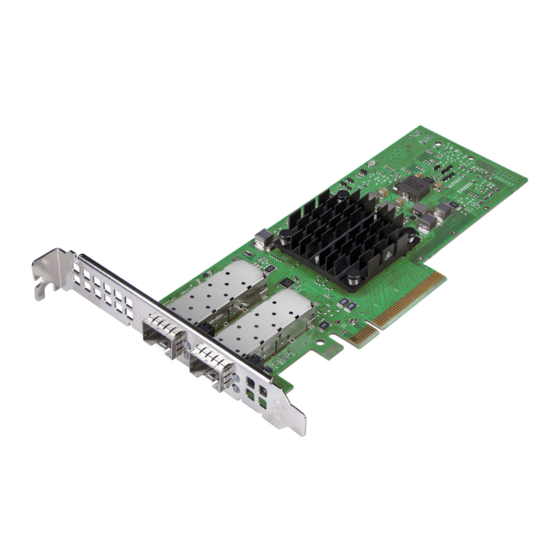
- Page 11 NetXtreme-E User’s Manual Functional Description Figure 2: BCM957404A4041DLPC, BCM957414A4141D Network Interface Card February 26, 2018 • NetXtreme-E-UG100 Page 11...
- Page 12 NetXtreme-E User’s Manual Functional Description Figure 3: BCM957406A4060DLPC, BCM957416A4160D Network Interface Card Figure 4: BCM957414M4140D Network Daughter Card (rNDC) February 26, 2018 • NetXtreme-E-UG100 Page 12...
- Page 13 NetXtreme-E User’s Manual Functional Description Figure 5: BCM957412M4120D Network Daughter Card (rNDC) Figure 6: BCM957416M4160 Network Daughter Card (rNDC) February 26, 2018 • NetXtreme-E-UG100 Page 13...
-
Page 14: Network Link And Activity Indication
NetXtreme-E User’s Manual Network Link and Activity Indication Network Link and Activity Indication BCM957402AXXXX/BCM957412AXXXX The SFP+ port has two LEDs to indicate traffic activities and link speed. The LEDs are visible through the cutout on the bracket as shown in Figure 7. -
Page 15: Bcm957404Axxxx/Bcm957414Axxxx
NetXtreme-E User’s Manual Network Link and Activity Indication BCM957404AXXXX/BCM957414AXXXX The SFP28 port has two LEDs to indicate traffic activities and link speed. The LEDs are visible through the cutout on the bracket as shown in Figure 8. The LED functionality is described in Table Figure 8: BCM957404AXXXX/BCM957414AXXXX Activity and Link LED Locations Port 1 SFP28 Cage... -
Page 16: Bcm957406Axxxx/Bcm957416Axxxx
NetXtreme-E User’s Manual Network Link and Activity Indication BCM957406AXXXX/BCM957416AXXXX The RJ-45 port has two LEDs to indicate traffic activities and link speed. The LEDs are visible through the cutout on the bracket as shown in Figure 9. The LED functionality is described in Table Figure 9: BCM957406AXXXX/BCM957416AXXXX Activity and Link LED Locations Table 8: BCM957406AXXXX/BCM957416AXXXX Activity and Link LED Locations... -
Page 17: Bcm957414M4140D
NetXtreme-E User’s Manual Network Link and Activity Indication BCM957414M4140D The SFP28 port has two LEDs to indicate traffic activities and link speed. The LEDs are visible through the cutout on the bracket as shown in Figure Figure 10: BCM957414M4140D Network Daughter Card (rNDC) Activity and Link LED Locations Table 9: BCM957414M4140D Network Daughter Card (rNDC) Activity and Link LED Locations LED Type Color/Behavior... -
Page 18: Bcm957412M4120D
NetXtreme-E User’s Manual Network Link and Activity Indication BCM957412M4120D This rNDC has SFP+ and RJ-45 ports, each with two LEDs to indicate traffic activities and link speed. The LEDs are visible as shown in Figure Figure 11: BCM957412M4120D Network Daughter Card (rNDC) Activity and Link LED Locations Table 10: BCM957412M4120D Network Daughter Card (rNDC) Activity and Link LED Locations SFP+ Port 1 and 2 LED Type... -
Page 19: Bcm957416M4160
NetXtreme-E User’s Manual Network Link and Activity Indication BCM957416M4160 This rNDC has 10GBaseT and 1000BaseT RJ-45 ports, each with two LEDs to indicate traffic activities and link speed. The LEDs are visible as shown in Figure Figure 12: BCM957416M4160 Network Daughter Card (rNDC) Activity and Link LED Locations Table 12: BCM957416M4160 Network Daughter Card (rNDC) Activity and Link LED Locations 10GBaseT Port 1 and 2 LED Type... -
Page 20: Features
NetXtreme-E User’s Manual Features Features Refer to the following sections for device features. Software and Hardware Features Table 13 provides a list of host interface features. Table 13: Host Interface Features Feature Details Host Interface PCIe v3.0 (Gen 3: 8 GT/s; Gen 2: 5 GT/s; Gen 1: 2.5 GT/s). -
Page 21: Virtualization Features
NetXtreme-E User’s Manual Features Table 13: Host Interface Features (Cont.) Feature Details Jumbo Frames Supported. iSCSI boot Supported. NIC Partitioning (NPAR) Supports up to eight Physical Functions (PFs) per port, or up to 16 PFs per silicon. This option is configurable in NVRAM. -
Page 22: Vxlan
NetXtreme-E User’s Manual Features VXLAN A Virtual eXtensible Local Area Network (VXLAN), defined in IETF RFC 7348, is used to address the need for overlay networks within virtualized data centers accommodating multiple tenants. VXLAN is a Layer 2 overlay or tunneling scheme over a Layer 3 network. Only VMs within the same VXLAN segment can communicate with each other. -
Page 23: Stateless Transport Tunnel Offload
NetXtreme-E User’s Manual Features Stateless Transport Tunnel Offload Stateless Transport Tunnel Offload (STT) is a tunnel encapsulation that enables overlay networks in virtualized data centers. STT uses IP-based encapsulation with a TCP-like header. There is no TCP connection state associated with the tunnel and that is why STT is stateless. Open Virtual Switch (OVS) uses STT. An STT frame contains the STT frame header and payload. -
Page 24: Sr-Iov
The original PCIe definition allowed for eight PFs per device. For Alternative Routing-ID (ARI) capable systems, Broadcom NetXtreme-E adapters support up to 16 PFs per device. Each partition is assigned its own configuration space, BAR address, and MAC address allowing it to operate independently. Partitions support direct assignment to VMs, VLANs, etc., just as any other physical interface. -
Page 25: Supported Combinations
NetXtreme-E User’s Manual Features Supported Combinations The following sections describe the supported feature combinations for this device. NPAR, SR-IOV, and RoCE Table 15 provides the supported feature combinations of NPAR, SR-IOV, and RoCE. Table 15: NPAR, SR-IOV, and RoCE SW Feature Notes NPAR Up to 8 PFs or 16 PFs... -
Page 26: Installing The Hardware
Install or remove adapters in a static-free environment. The use of a properly grounded wrist strap or other personal antistatic devices and an antistatic mat is strongly recommended. System Requirements Before you install the Broadcom NetXtreme-E Ethernet adapter, verify that the system meets the requirements listed for the operating system. Hardware Requirements Refer to the following list of hardware requirements: •... -
Page 27: Installing The Adapter
Installing the Hardware Installing the Adapter The following instructions apply to installing the Broadcom NetXtreme-E Ethernet adapter (add-in NIC) into most servers. Refer to the manuals that are supplied with the server for details about performing these tasks on this particular server. -
Page 28: Copper
NetXtreme-E User’s Manual Installing the Hardware Table 17: Supported Cables and Modules (Cont.) Optical Module Dell Part Number Adapters Description FTLX8574D3BCL-FC WTRD1 BCM57402X, BCM57404X, 10 Gbps-SR SFP+ Transceiver BCM57412X, BCM57414X PLRXPLSCS43811 Note: 1. Direct Attach Cables (DAC) that conform to IEEE standards can be connected to the adapter. 2. -
Page 29: Software Packages And Installation
Refer to the following sections for driver installation. Windows Dell DUP Broadcom NetXtreme E series controller drivers can be installed using the driver DUP. The installer is provided in x64 executable format. GUI Install When the file is executed, a dialog box appears requesting user input. The installer supports the driver only option. -
Page 30: Linux
NetXtreme-E User’s Manual Software Packages and Installation Once the files are extracted, INF installation is executed through "upgrade driver" functionality using the Device Manager (devmgmt.msc). Open the Device Manager, select the desired NIC, right click and select the upgrade driver to update it. Linux The Linux drivers are supplied in RPM, KMP, and source code format. -
Page 31: Linux Ethtool Commands
NetXtreme-E User’s Manual Software Packages and Installation Linux Ethtool Commands Note: In Table 19, ethX should be replaced with the actual interface name. Table 19: Linux Ethtool Commands Command Description ethtool -s ethX speed 25000 autoneg off Set the speed. If the link is up on one port, the driver will not allow the other port to be set to an incompatible speed. -
Page 32: Vmware
NetXtreme-E User’s Manual Software Packages and Installation Table 19: Linux Ethtool Commands (Cont.) Command Description ip link set ethX vf 0 mac 00:12:34:56:78:9a Set VF MAC address. ip link set ethX vf 0 state enable Set VF link state for VF 0. ip link set ethX vf 0 vlan 100 Set VF 0 with VLAN ID 100. -
Page 33: Firmware Update
Refer to the following sections to use the Dell Update Package (DUP): Windows Broadcom NetXtreme-E series controller firmware can be upgraded using the Dell DUP package. The executable is provided in standard Windows x64 executable format. Double-click on the file to execute it. -
Page 34: Windows Driver Advanced Properties And Event Log Messages
NetXtreme-E User’s Manual Windows Driver Advanced Properties and Event Log Messages Windows Driver Advanced Properties and Event Log Messages Driver Advanced Properties The Windows driver advanced properties are shown in Table Table 21: Windows Driver Advanced Properties Driver Key Parameters Description Encapsulated Task offload Enable or Disable... -
Page 35: Event Log Messages
NetXtreme-E User’s Manual Windows Driver Advanced Properties and Event Log Messages Table 21: Windows Driver Advanced Properties (Cont.) Driver Key Parameters Description SR-IOV Enable or Disable. Default Enabled. This parameter works in conjunction with HW configured SR-IOV and BIOS configured SR-IOV setting. TCP/UDP checksum offload IPV4 TX/RX enabled, TX enabled or RX Default RX and TX enabled. - Page 36 NetXtreme-E User’s Manual Windows Driver Advanced Properties and Event Log Messages Table 23: Event Log Messages (Cont.) 0x001A Incompatible speed selection between Port 1 and Port 2. Reported link speeds are correct and might not match Speed and Duplex setting. 0x001B Incompatible speed selection between Port 1 and Port 2.
-
Page 37: Teaming
Teaming Teaming Windows The Broadcom NetXtreme-E devices installed on Dell platforms can participate in NIC teaming functionality using the Microsoft teaming solution. Refer to Microsoft public documentation described in the following link: https://www.microsoft.com/en-us/download/details.aspx?id=40319 Microsoft LBFO is a native teaming driver that can be used in the Windows OS. The teaming driver also provides VLAN tagging capabilities. -
Page 38: System-Level Configuration
Refer to the following sections for information on system-level NIC configuration. UEFI HII Menu Broadcom NetXtreme-E series controllers can be configured for pre-boot, iscsi and advanced configuration such as SR-IOV using HII (Human Interface) menu. To configure the settings, during system boot select F2 -> System Setup -> Device Settings. Select the desired network adapter for viewing and changing the configuration. -
Page 39: Comprehensive Configuration Management
Preboot configuration can be configured using the Comprehensive Configuration Management (CCM) menu option. During the system BIOS POST, the Broadcom banner message will be displayed with an option to change the parameters through the Control-S menu. When Control-S is pressed, a device list will be populated with all the Broadcom network adapters found in the system. -
Page 40: Auto-Negotiation Configuration
AN. Ensure that the link partner port has been set to the matching auto-negotiation protocol. For example, if the local Broadcom port is set to IEEE 802.3by AN protocol, the link partner must support AN and must be set to IEEE 802.3by AN protocol. - Page 41 System-level Configuration NetXtreme-E User’s Manual Table 24: Supported Combination of Link Speed Settings Port 2 Link Setting Port1 Link Speed AN Enabled AN Enabled AN Enabled {1/ AN Enabled {1/ AN Enabled {10/ AN Enabled {1/10/ Setting Forced 1G Forced 10G Forced 25G AN Enabled {1G} {10G}...
- Page 42 System-level Configuration NetXtreme-E User’s Manual • {link speed} – expected link speed • AN {link speeds} – advertised supported auto-negotiation link speeds. The expected link speeds based on the local and link partner settings are shown in Table Table 25: Expected Link Speeds Link Partner Speed Settings Local Speed Forced...
-
Page 43: Operational Link Speed
This is the supported auto-negotiation protocol used to negotiate the link speed with the link partner. This option must match the AN protocol setting in the link partner port. The Broadcom NetXtreme-E NIC supports the following auto-negotiation protocols: IEEE 802.3by, 25G/50G consortiums and 25G/50G BAM. By default, this option is set to IEEE 802.3by and falls back to 25G/50G consortiums. -
Page 44: Esxi Driver Settings
NetXtreme-E User’s Manual System-level Configuration The following are supported advertised speeds. • 0x020 – 1000baseT Full • 0x1000 – 10000baseT Full • 0x80000000 – 25000baseCR Full ethtool -A eth0 autoneg on|off Use this command to enable/disable Pause frame auto-negotiation. ethtool -a eth0 Use this command to display the current flow control auto-negotiation setting. -
Page 45: Fec Auto-Negotiation
NetXtreme-E User’s Manual System-level Configuration FEC Auto-Negotiation To enable/disable Link FEC auto-negotiation, the following options can be enabled in the system BIOS HII menu or in CCM: • System BIOS->Device Settings->NetXtreme-E NIC->Device Level Configuration The FEC Auto-negotiation uses two parameters during negotiation exchange: FEC capable and FEC request. If the NIC advertises it as FEC Auto-negotiation capable, then the FEC settings are driven by the Switch. -
Page 46: Link Training
F0 and F1 bits on IEEE802.3by and the F2 and F4 bits on Consortium. Link Training Link training allows both endpoints, the Broadcom adapter and the other side, to adjust power settings and other tuning parameters to maximize the reliability and efficiency of the communication channel between the two devices. -
Page 47: Media Auto Detect
NetXtreme-E User’s Manual System-level Configuration Table 28: Link Training Relationship Between Media Type and Speed Link Partner Link Training Setting Force Speed Link Force Speed Link Local and Media Cable Type Training Disabled Training Enabled AN (Auto-Link Training) Force Speed DAC (SFP+/SFP28/ Link without Link Link with Link Training Link with Link Training... - Page 48 NetXtreme-E User’s Manual System-level Configuration Table 29 Table 30 show the link results with the Media Auto Detect feature enabled. Table 29: Media Auto Detect for the BCM5730X and BCM5740X Link Partner Link Training Setting Link Partner Settings Media Auto Detect Speed No FEC Base-R FEC...
-
Page 49: Iscsi Boot
ISCSI Boot ISCSI Boot Broadcom NetXtreme-E Ethernet adapters support iSCSI boot to enable the network boot of operating systems to diskless systems. iSCSI boot allows a Windows, Linux, or VMware operating system to boot from an iSCSI target machine located remotely over a standard IP network. -
Page 50: Configuring Iscsi Boot Parameters
NetXtreme-E User’s Manual ISCSI Boot Configuring iSCSI Boot Parameters Configure the Broadcom iSCSI boot software for either static or dynamic configuration. Refer toTable 31 configuration options available from the General Parameters menu. Table 31 lists parameters for both IPv4 and IPv6. -
Page 51: Iscsi Boot Configuration
NetXtreme-E User’s Manual ISCSI Boot 3. From the MBA Configuration Menu, use the UP ARROW or DOWN ARROW to move to the Boot Protocol option. Use the LEFT ARROW or RIGHT ARROW to change the Boot Protocol option for iSCSI. Select iSCSI Boot Configuration from Main Menu. -
Page 52: Dynamic Iscsi Boot Configuration
If DHCP Option 17 is used, the target information is provided by the DHCP server, and the initiator iSCSI name is retrieved from the value programmed from the Initiator Parameters screen. If no value was selected, then the controller defaults to the name: iqn.1995-05.com.broadcom.<11.22.33.44.55.66>.iscsiboot where the string 11.22.33.44.55.66 corresponds to the controller's MAC address. •... -
Page 53: Enabling Chap Authentication
NetXtreme-E User’s Manual ISCSI Boot To configure the iSCSI boot parameters using a dynamic configuration: From the General Parameters menu screen, set the following parameters: • TCP/IP parameters via DHCP – Enabled. (For IPv4.) • IP Autoconfiguration – Enabled. (For IPv6, non-offload.) •... -
Page 54: Configuring The Dhcp Server To Support Iscsi Boot
40 within the option 17 parameter on the DHCP server. <targetname> The target name in either IQN or EUI format (refer to RFC 3720 for details on both IQN and EUI formats). An example IQN name would be "iqn.1995-05.com.broadcom:iscsi- target". DHCP Option 43, Vendor-Specific Information DHCP option 43 (vendor-specific information) provides more configuration options to the iSCSI client than DHCP option 17. -
Page 55: Configuring The Dhcp Server
DHCPv6 client. For iSCSI boot, Broadcom adapters support the following DHCP configurations: Note: The DHCPv6 standard Root Path option is not yet available. Broadcom suggests using Option 16 or Option 17 for dynamic iSCSI Boot IPv6 support. -
Page 56: Configuring The Dhcp Server
NetXtreme-E User’s Manual VXLAN: Configuration and Use Case Examples Table 34: DHCP Option 17 Suboption Definition Suboption Definition First iSCSI target information in the standard root path format "iscsi:"[<servername>]":"<protocol>":"<port>": "<LUN>":"<targetname>" iSCSI initiator IQN Note: In Table 34, the brackets [ ] are required for the IPv6 addresses. The content of option 17 should be <2-byte Option Number 201|202|203>... -
Page 57: Sr-Iov: Configuration And Use Case Examples
Note: x represents the PCIe bus number of the physical adapter found in the system. y represents the port number on the physical adapter. SR-IOV: Configuration and Use Case Examples SR-IOV can be configured, enabled, and used on 10Gb and 25Gb Broadcom NetExtreme-E NICs. Linux Use Case 1. Enable SR-IOV in the NIC cards: a. -
Page 58: Windows Case
NetXtreme-E User’s Manual SR-IOV: Configuration and Use Case Examples Note: Use to install both for RDMA netxtreme-bnxt_en<version>.tar.gz bnxt_re bnxt_en functionality on SRIOV VFs. 6. Enable Virtual Functions through Kernel parameters: a. Once the driver is installed, lspci will display the NetXtreme-E NICs present in the system. Bus, device, and Function are needed for activating Virtual functions. -
Page 59: Vmware Sriov Case
NetXtreme-E User’s Manual SR-IOV: Configuration and Use Case Examples c. Set the number of virtual functions per physical function. d. Set the number of MSI-X vectors per the VF and Max number of physical function MSI-X vectors. If the VF is running out of resources, balance the number of MSI-X vectors per VM using CCM. 2. - Page 60 Verify that whether drivers are correctly installed: $ esxcli software vib list | grep bnxtnet 4. Install the Broadcom provided BNXTNETCLI (esxcli bnxtnet) utility to set/view the miscellaneous driver parameters that are not natively supported in esxcli, such as: link speed to 25G, show driver/firmware chip information, show NIC configuration (NPAR, SRIOV).
- Page 61 NetXtreme-E User’s Manual SR-IOV: Configuration and Use Case Examples 5. Enabling SRIOV VFs: Only the PFs are automatically enabled. If a PF supports SR-IOV, the PF(vmknicX) is part of the output of the command shown below. esxcli network sriovnic list To enable one or more VFs, the driver uses the module parameter "max_vfs"...
-
Page 62: Npar - Configuration And Use Case Example
VFs + RDMA per physical device. Configuration NPAR can be configured using BIOS configuration HII menus or by using the Broadcom CCM utility on legacy boot systems. Some vendors also expose the configuration via additional proprietary interfaces. - Page 63 NetXtreme-E User’s Manual NPAR – Configuration and Use Case Example NPAR is enabled in combination with SR-IOV. For some ARI capable OEM systems, the NParEP button is available to explicitly allow the BCM5741X to support up to 16 partitions. Switching from Single Function mode to Multifunction mode, the device needs to be re-enumerated, therefore changes will not take effect until a system reboot occurs.
- Page 64 NetXtreme-E User’s Manual NPAR – Configuration and Use Case Example 4. Set the NIC Partition Configuration parameters (see Table 37 on page 64). Table 37: NPAR Parameters Parameter Description Valid Options BW Reservation Percentage of total available bandwidth that should be reserved for Value 0-100 this partition.
-
Page 65: Notes On Reducing Nic Memory Consumption
NetXtreme-E User’s Manual NPAR – Configuration and Use Case Example Notes on Reducing NIC Memory Consumption Because of the faster link speeds supported in this NIC, the default number of receive buffers is larger. More packets can arrive within a given time interval when the link speed is higher, and if the host system is delayed in processing the receive interrupts, the NIC must drop packets if all available receive buffers are in use. -
Page 66: Roce - Configuration And Use Case Examples
NetXtreme-E User’s Manual RoCE – Configuration and Use Case Examples RoCE – Configuration and Use Case Examples This section provides configuration and use case examples for RoCE. To enable RoCE for PFs or VFs, the user must enable the RDMA selection in the HII menu in the BIOS before the RDMA option takes effect in the host or guest OS. -
Page 67: Installation
NetXtreme-E User’s Manual RoCE – Configuration and Use Case Examples To compile bnxt_re: $make • Distros that need external OFED to be installed: SLES11SP4 Please refer OFED release notes from the following link and install OFED before compiling bnxt_re driver. http://downloads.openfabrics.org/downloads/OFED/release_notes/OFED_3.18-2_release_notes To compile bnxt_re: $export OFED_VERSION=OFED-3.18-2... -
Page 68: Windows
Windows Server 2012 and beyond invokes the RDMA capability in the NIC for SMB file traffic if both ends are enabled for RDMA. Broadcom NDIS miniport bnxtnd.sys v20.6.2 and beyond support RoCEv1 and RoCEv2 via the NDKPI interface. The default setting is RoCEv1. -
Page 69: User Mode
NetXtreme-E User’s Manual RoCE – Configuration and Use Case Examples Client Side: • Enable: Set-SmbClientConfiguration -EnableMultiChannel $true • Disable: Set-SmbClientConfiguration -EnableMultiChannel $false Note: By default, the driver sets up two RDMA connections for each network share per IP address (on a unique subnet). -
Page 70: Vmware Esx
NetXtreme-E User’s Manual RoCE – Configuration and Use Case Examples VMware ESX Limitations The current version of the RoCE supported driver requires ESXi-6.5.0 GA build 4564106 or above. BNXT RoCE Driver Requirements The BNXTNET L2 driver must be installed with the module parameter before installing the disable_roce=0 driver. -
Page 71: Configuring Paravirtualized Rdma Network Adapters
NetXtreme-E User’s Manual RoCE – Configuration and Use Case Examples Configuring Paravirtualized RDMA Network Adapters Please refer to the vmware link below for additional information on setting up and using Paravirtualized RDMA (PVRDMA) network adapters. https://pubs.vmware.com/vsphere-65/index.jsp#com.vmware.vsphere.networking.doc/GUID-4A5EBD44- FB1E-4A83-BB47-BBC65181E1C2.html Configuring a Virtual Center for PVRDMA To configure a Virtual Center for PVRDMA: 1. -
Page 72: Configuring The Vm On Linux Guest Os
NetXtreme-E User’s Manual RoCE – Configuration and Use Case Examples Configuring the VM on Linux Guest OS Note: The user must install the appropriate development tools including git before proceeding with the configuration steps below. 1. Download the PVRDMA driver and library using the following commands: git clone git://git.openfabrics.org/~aditr/pvrdma_driver.git git clone git://git.openfabrics.org/~aditr/libpvrdma.git 2. -
Page 73: Dcbx - Data Center Bridging
DCBX – Data Center Bridging DCBX – Data Center Bridging Broadcom NetXtreme-E controllers support IEEE802.1Qaz DCBX as well as the older CEE DCBX specification. DCB configuration is obtained by exchanging the locally configured settings with the link peer. Since the two ends of a link may be configured differently, DCBX uses a concept of 'willing' to indicate which end of the link is ready to accept parameters from the other end. -
Page 74: Dcbx Mode = Enable (Ieee Only)
After enabling the indicated options in the UEFI HII menu to set firmware level settings, perform the follow selection in the Windows driver advanced properties. Open Windows Device Manager -> Broadcom NetXtreme E Series adapter -> Advanced Properties -> Advanced tab Quality of Service = Enabled Priority &... - Page 75 NetXtreme-E User’s Manual DCBX – Data Center Bridging C:\> Get-NetQoSTrafficClass Name Algorithm Bandwidth(%) Priority --------------------------- [Default] 0-3,5-7 SMB class Use the following in modifying the Traffic Class: PS C:\> Set-NetQoSTrafficClass -Name "SMB class" -BandwidthPercentage 40 PS C:\> get-NetQosTrafficClass Name Algorithm Bandwidth(%) Priority ------------------------------------------------------------------ [Default] ETS 60 0-3,5-7...
- Page 76 NetXtreme-E User’s Manual DCBX – Data Center Bridging Note: The above command creates a new policy for SMB. –SMB is an inbox filter that matches TCP port 445 (reserved for SMB). If a packet is sent to TCP port 445 it will be tagged by the operating system with 802.1p value of 4 before the packet is passed to a network miniport driver.
-
Page 77: Frequently Asked Questions
NetXtreme-E User’s Manual Frequently Asked Questions Use the following to remove QoS Policy: PS C:\> Remove-NetQosPolicy -Name "Network Management" Frequently Asked Questions • Do you support AutoNeg at 25G speed? Yes. Please refer to “Auto-Negotiation Configuration” on page 40 for more details. •...
Need help?
Do you have a question about the NetXreme-C and is the answer not in the manual?
Questions and answers