
Related Manuals for Broadcom P411W-32P


Summary of Contents for Broadcom P411W-32P
- Page 1 P411W-32P PCIe 4.0 NVMe Switch Adapter User Guide Version 2.1 Broadcom P411W-32P-UG104 December 6, 2019...
- Page 2 The term “Broadcom” refers to Broadcom Inc. and/or its subsidiaries. For more information, please visit www.broadcom.com. Broadcom reserves the right to make changes without further notice to any products or data herein to improve reliability, function, or design. Information furnished by Broadcom is believed to be accurate and reliable. However, Broadcom does not assume any liability arising out of the application or use of this information, nor the application or use of any product or circuit described herein, neither does it convey any license under its patent rights nor the rights of others.
-
Page 3: Table Of Contents
P411W-32P NVMe Switch Adapter User Guide ........ -
Page 4: P411W-32P Nvme Switch Adapter User Guide
® The Broadcom P411W-32P NVMe PCIe 4.0 switch adapter (model number 50054) provides high-performance storage connectivity for servers and workstations. The adapter uses the PEX88048 PCIe 4.0 switch that provides a x16 PCIe 4.0, 16 GT/s interface to a host system with up to 32 PCIe 4.0 16 GT/s ports for NVMe device connection. -
Page 5: Backplane Management
P411W-32P PCIe 4.0 User Guide NVMe Switch Adapter Fedora FreeBSD 4 Backplane Management The adapter supports the industry standard SFF-TA-1005 Specification for Universal Backplane Management (UBM). UBM provides the following key features: Reports the backplane capabilities, including the following: ... - Page 6 P411W-32P PCIe 4.0 User Guide NVMe Switch Adapter Figure 1 Backplane with x8 Connectors The following figure represents a backplane that uses x4 connectors with one UBM target for each connector. The red line indicates the I C bus connection.
-
Page 7: Vpp-Based Backplanes
Figure 2 Backplane with x4 Connectors 4.2 VPP-Based Backplanes Broadcom requires new designs to enable UBM for backplane management. However, the adapter maintains support for Virtual Pin Port (VPP) backplane management for legacy implementations. If using x4 connectors on the backplane, each leg of the cable must connect to adjacent drives;... - Page 8 C for backplane management. The red line indicates the I2C bus connection. For proper LED functionality when using Broadcom supplied cables, connect the P0 labeled leg of the cable to the PCA9555 target. Refer to the backplane's documentation to verify which host facing connector maps to a given slot.
-
Page 9: Sideband Signals
P411W-32P PCIe 4.0 User Guide NVMe Switch Adapter Figure 4 Backplane with x8 Connectors and VPP 5 Sideband Signals The adapter has four x8 SFF-8654 connectors. Each x8 connector provides two sets of sidebands. This section describes the sideband signals usage. The following table defines the sideband signal’s pins on the SFF-8654 connector. The last column in the table indicates the strength of the pull-up resistor or pull-down resistor values on the adapter. - Page 10 Table 2 Sideband Management Pin Settings Pin Name Settings Description BP_TYPE 0: SGPIO (not supported) Backplanes must be set to the two-wire interface when using the P411W-32P NVMe 1: 2-Wire switch adapter. SGPIO is not supported. 2W_RESET# 0: Reset is asserted Optional reset driven by the host if the UBM target reports that the target can be reset.
-
Page 11: Connector Physical-To-Logical Mapping
P411W-32P PCIe 4.0 User Guide NVMe Switch Adapter 6 Connector Physical-to-Logical Mapping The following table shows the adapter's physical connector to logical connector mapping as viewed from the UART interface, when used with the bpview CLI command. The adapter uses x8 SFF-8654 connectors. Each connector is segregated into quads and mapped accordingly. -
Page 12: Cable Support
Adapter Label Tool Mapping Port Number Drive C0.1 C0.0 7 Cable Support Broadcom supports the following cables for use with the adapter. Table 6 Supported NVMe Switch Adapter Cables Cable Description Adapter Connector Backplane Connector 05-60001-00 x8 8654 to 2x4 8612, AltWiring 1M... -
Page 13: Connectors
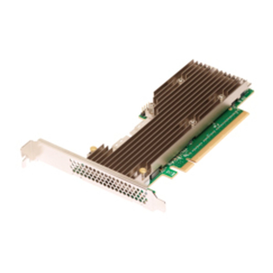
P411W-32P PCIe 4.0 User Guide NVMe Switch Adapter Figure 6 P411W-32P NVMe Switch Adapter Layout J1, J2, J3, J4 (C0, C1, C2, C3) – x8 SFF-8654 Slimline internal connectors J22 – UART. Reserved for Broadcom use. LED11 – SYS_ERROR_N LED ... -
Page 14: Electrical Characteristics
Typical power is measured with maximum I/O traffic, typical silicon process material, and nominal voltages operating the card at an ambient temperature of 45°C with required airflow.The power requirements for the adapter under normal operation are shown in the following table. Table 8 P411W-32P NVMe Switch Adapter Power Consumption Power Mode Typical Power 3.3V Supply... -
Page 15: Adapter Certifications And Safety Characteristics
9 Adapter Certifications and Safety Characteristics All Broadcom adapters meet or exceed the requirements of UL flammability rating 94V-0. Each bare board is marked with the supplier’s name or trademark, type, and UL flammability rating. Because these boards are installed in a PCIe bus slot, all voltages are less than the SELV 42.4V limit. -
Page 16: Hardware Installation Instructions
P411W-32P PCIe 4.0 User Guide NVMe Switch Adapter Table 9 Adapter Marks and Certifications (Continued) Mark Symbol Description Taiwan Meets the following standards: (BSMI) CNS 13438 CNS15663 USA / For use with UL listed ITE equipment only. Canada... - Page 17 PCIe slot. The shape, size, and locations of the components on your adapter and its bracket might vary from this illustration. NOTE: Figure 7 Install the P411W-32P NVMe Switch Adapter in a PCIe Slot Bracket Screw Bracket Screw...
-
Page 18: Firmware Download Operation
The hardware installation of your adapter is complete. 11 Firmware Download Operation Use the g4Xflash tool to update the firmware on your adapter. Download the g4Xflash tool from the Broadcom download center, https://www.broadcom.com/support/download-search. Use the following command to download the firmware and manufacturing image to the Flash memory on the adapter. -
Page 19: Revision History
Table 7, Internal Connector Pinout. Preliminary, Version 1.1, September 7, 2018 The following document change was made: Added the adapter model number to Section , P411W-32P NVMe Switch Adapter User Guide. Preliminary, Version 1.0, August 29, 2018 Initial document release. Broadcom...
Need help?
Do you have a question about the P411W-32P and is the answer not in the manual?
Questions and answers