Advertisement
Quick Links
Window actuator flush-mounted
Order-No. : 2164 00
Blind actuator 1-gang flush-mounted
Order-No. : 2165 00
Heating actuator 1-gang flush-mounted
Order-No. : 2166 00
Operating instructions
1 Safety instructions
Electrical equipment may only be installed and fitted by electrically skilled persons.
Failure to observe the instructions may cause damage to the device and result in fire and
other hazards.
The device is not suitable for disconnection from supply voltage.
The connected actuators are not electrically isolated from the mains – even when
switched off.
Do not connect any external voltage to the inputs, since doing so may damage the
device(s), and the SELV potential on the KNX bus line will no longer be available.
For parallel connection of several drives to an output it is essential to observe the
corresponding instructions of the manufacturers, and to use a cut-off relay if necessary.
There is otherwise risk of irreparable damage to the drives.
Use only shutter drives with mechanical or electronic limit switches. Check the limit
switches for correct adjustment. Observe the specifications of the motor manufacturers.
These instructions are an integral part of the product, and must remain with the end
customer.
2 Device components
Figure 1: Window actuator
32572302
10499188 I00
20.05.2011
1/8
Advertisement

Subscribe to Our Youtube Channel
Related Manuals for Gira 2164 00


Summary of Contents for Gira 2164 00
- Page 1 Window actuator flush-mounted Order-No. : 2164 00 Blind actuator 1-gang flush-mounted Order-No. : 2165 00 Heating actuator 1-gang flush-mounted Order-No. : 2166 00 Operating instructions 1 Safety instructions Electrical equipment may only be installed and fitted by electrically skilled persons.
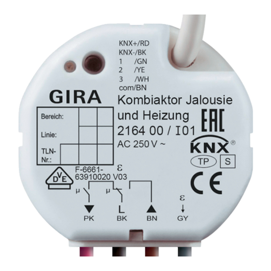
- Page 2 Figure 2: Venetian blind actuator Figure 3: Heating actuator (1) Control cable (2) Programming button and LED (3) Connection of mains and power cables Connection assignment, power cables BK, black: connection L BN, brown: connection of Venetian blind, up PK, pink: connection of Venetian blind, down GY, grey: actuator connection 32572302 10499188 I00...
- Page 3 Figure 4 Connection assignment of control cable RD, red: KNX+ BK, black: KNX– GN, green: input 1 YE, yellow: input 2 WH, white: input 3 BN, brown: COM inputs 1...3 3 Function System information This device is a product of the KNX system and complies with the KNX directives. Detailed technical knowledge obtained in KNX training courses is a prerequisite to proper understanding.
- Page 4 Three binary inputs for potential-free contacts, usable as extension inputs for local operation Supply via bus, no additional power supply necessary Blind function Blind position directly controllable Slat position directly controllable Feedback of movement status, blind position and slat position Forced position through higher-level controller Safety function: 3 independent wind alarms, rain alarm, frost alarm Sun protection function...
- Page 5 Figure 5 (4) Appliance box (5) Partition (6) Potential-free contacts, e.g. for window contact or installation pushbuttons Figure 6 Minimum spacing between the mains voltage and bus/extension wires: 4 mm (Figure 6). Connect the load (Figure 7). Use the supplied sprung screwless terminals. Flexible cable ends must be tin-plated.
- Page 6 Assign physical addresses and load application software into the device. Note the physical address on the device label. 5 Appendix 5.1 Technical data Window actuator flush-mounted, Order-No. 2164 00 Supply Rated voltage AC 230 / 240 V ~ Mains frequency...
- Page 7 Heating output Output type Semi-conductor (Triac), ε Switching current 5 ... 25 mA Switch-on current max. 600 mA (2 sec) Number of drives per output max. 2 Control cable and inputs Control cable (preterminated) YY6x0.6 Input type Potential-free Total length of extension unit cable max.
-
Page 8: Warranty
The warranty is provided in accordance with statutory requirements via the specialist trade. Please submit or send faulty devices postage paid together with an error description to your responsible salesperson (specialist trade/installation company/electrical specialist trade). They will forward the devices to the Gira Service Center. Gira Giersiepen GmbH & Co. KG...
Need help?
Do you have a question about the 2164 00 and is the answer not in the manual?
Questions and answers