Sign In
Upload
Download
Table of Contents
Contents
Add to my manuals
Delete from my manuals
Share
URL of this page:
HTML Link:
Bookmark this page
Add
Manual will be automatically added to "My Manuals"
Print this page
×
Bookmark added
×
Added to my manuals
Manuals
Brands
Esu Manuals
Media Converter
51801
Instruction manual
Esu 51801 Instruction Manual
Switchpilot v2.0, switchpilot extension v1.0
Hide thumbs
Also See for 51801
:
User manual
(32 pages)
1
Table Of Contents
2
3
4
5
6
7
8
9
10
11
12
13
14
15
16
17
18
19
20
21
22
23
24
25
26
27
28
29
30
31
32
page
of
32
Go
/
32
Contents
Table of Contents
Bookmarks
Table of Contents
Table of Contents
Declaration of Conformity
WEEE Delaration
Important Notes - Please Read this Chapter First
How this Manual will Help You
Introduction - the Switchpilot Family
Members of the Switchpilot Family
Switchpilot Overview
Switchpilot V2.0
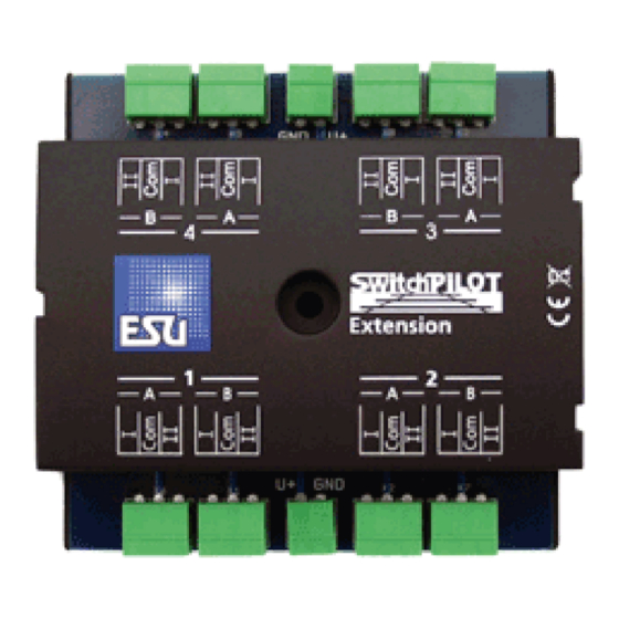
Switchpilot Extension
Features
Operational Modes
K83 Mode
K84 Mode
3.User Mode
Transistor Outputs
Servo Outputs
Conventional Servos
Digital Servos
ESU Servo Motor
Feedback Inputs
Connection to the Digital System
Connecting Elements of the Switchpilot
Power Supply from the Digital System
Separate Power Supply
Wiring of Transistor Outputs
Connecting Double-Coil Solenoids
Wiring Daylight Signals and Light Bulbs or Leds
Wiring a Servo
Wiring Feedback Contacts
Wiring the Switchpilot Extension
Relay Outputs
Wiring a Motor Drive
LGB® Motor Drive
Polarizing Electric Frogs
Decoder Settings (Programming)
Changeable Decoder Settings
Configuration Variables (CV)
Standardization Regarding NMRA
Bits und Bytes
Programming with DCC Systems
Programming on the Programming Track
Connecting to the Programming Track
Programming on the Main Track
Programming with Märklin® Central Stations
Programming with the ESU Lokprogrammer
Address Settings
Turnout Numbers
Decoder Address
Schedule of Turnout Numbers and Addresses
Factory Settings
Programming Addresses with Programming Button
First Address for Outputs 1 - 4
Second Address for Outputs 5 - 6
Parameters of the Transistor Outputs
Configuration of Output with Variable Duration (K83)
Output Configuration to Pulsed Output
Configuration of an Output for PECO Solenoid Drives
Configuration for Continuous Operation (K84)
Configuring the „Zoom"-Effect
Configuration of Servo End Position „B
Configuration of Servo Speed
Disabling the Pulse Signal and Power Supply
Configuration of Servo End Position „A
Features of Servo Outputs
Railcom
How to Activate Railcom
How to Read out Cvs with Railcom® and ESU Ecos
Feedback of Turnout Position with the Ecos
Options for Switchpilot Extension
Time of Switching
Assignment of Relays
Decoder Reset
With DCC Systems
With Programming Button
With ESU Lokprogramer
Support and Assistance
Technical Data
Technical Data Switchpilot V2.0
Technical Data Switchpilot Extension
List of All Supported Cvs
Warranty Certificate
Advertisement
Quick Links
1
Table of Contents
2
Switchpilot V2.0
3
Switchpilot Overview
4
Switchpilot Extension
5
Connection to the Digital System
Download this manual
SwitchPilot V2.0
Instruction Manual
4 . E d i t i o n , D e c e m b e r 2 0 1 7
SwitchPilot V2.0
SwitchPilot Extension V1.0
P/N 04213-13564
Table of
Contents
Previous
Page
Next
Page
1
2
3
4
5
Advertisement
Table of Contents
Need help?
Do you have a question about the 51801 and is the answer not in the manual?
Ask a question
Questions and answers
Related Manuals for Esu 51801
Media Converter Esu SwitchPilot User Manual
(32 pages)
Media Converter Esu 51820 Instruction Manual
Switchpilot v2.0, switchpilot extension v1.0 (32 pages)
Media Converter Esu LokPilot 52600 Quick Start Manual
(2 pages)
Media Converter Esu 51800 User Manual
(32 pages)
Media Converter Esu 51802 User Manual
(32 pages)
Media Converter Esu LokSound 5 DCC Instruction Manual
(16 pages)
Media Converter Esu SignalPilot 51840 Instruction Manual
(32 pages)
Media Converter Esu LokSound 5 Installation And Operating Instructions Manual
(112 pages)
Media Converter Esu 50097 Instruction Manual
(12 pages)
Media Converter Esu 51832 Instruction Manual
Servo decoder (40 pages)
Media Converter Esu PowerPack Mini Instruction Manual
(2 pages)
Media Converter Esu LokPilot 5 Basic Manual
(4 pages)
Media Converter Esu LokSound User Manual
(48 pages)
Media Converter Esu LokPilot V4.0 Instruction Manual
Lokpilot v4.0 series (76 pages)
Media Converter Esu SwitchPilot 3 51830 Instruction Manual
(36 pages)
Media Converter Esu L.Net converter Instruction Manual
(12 pages)
This manual is also suitable for:
51820
Table of Contents
Print
Rename the bookmark
Delete bookmark?
Delete from my manuals?
Login
Sign In
OR
Sign in with Facebook
Sign in with Google
Upload manual
Upload from disk
Upload from URL


Need help?
Do you have a question about the 51801 and is the answer not in the manual?
Questions and answers