Table of Contents
Advertisement
Quick Links
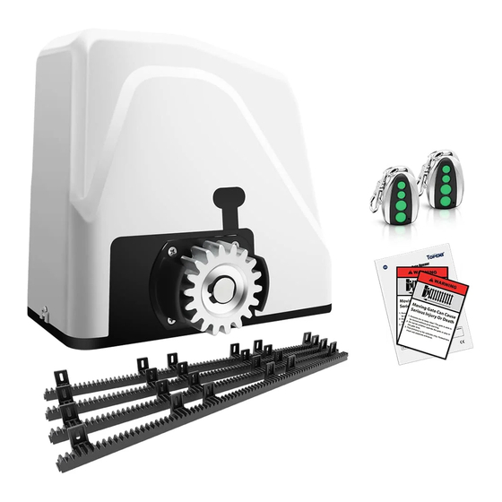
Sliding Gate Opener
User's Manual
Model:
RK1100(T)
TOPENS Website
www.topens.com
Email: support@topens.com
★ Please read and follow all warnings, precautions and instructions before
installation and use.
★ Periodic checks of the opener are required to ensure safe operation.
★ Save this manual.
C030625
VER 22c
Advertisement
Table of Contents

Subscribe to Our Youtube Channel
Related Manuals for Topens RK1100T


Summary of Contents for Topens RK1100T
- Page 1 Sliding Gate Opener User’s Manual Model: RK1100(T) TOPENS Website www.topens.com Email: support@topens.com ★ Please read and follow all warnings, precautions and instructions before installation and use. ★ Periodic checks of the opener are required to ensure safe operation. ★ Save this manual.
- Page 2 Visit: www.topens.com Please record the product model, your email address etc. in the spaces provided below. Refer to this list when contacting TOPENS for technical service or assistance with your automatic gate opener. Where did you purchase? (Amazon.com; Amazon.ca: Amazon.co.uk, Amazon.de; Other, Please...
-
Page 3: Table Of Contents
Parts List ..................................... 4 Extra Parts for RK1100T ..............................4 Accessories Parts (Included in some models, refers to the actual package) ..............4 Optional Accessories Parts List (Available at TOPENS Store) ..................4 Replacement Parts ................................5 Technical Specifications & Features ..........................5 Installation Overview ................................6... -
Page 4: Check Your Gate Before Installation
Thank you for purchasing our sliding gate opener. We are sure that the products will be greatly satisfying as soon as you start to use it. The product is supplied with a user’s manual which encloses installation and safety precautions. These should be read carefully before installation and operation as they provide important information about safety, installation, operation and maintenance. -
Page 5: Preparation For Installation
danger caused by squashing, conveying and shearing. • Position at least one visible indication device, and fix a Warning sign to the structure. • The factory declines all responsibility with respect to the automation safety and correct operation when other supplier’s components are used. •... - Page 6 In sake of safety, a positive stop must be mounted on the two end of ground track.
-
Page 7: Parts List
Parts List Extra Parts for RK1100T Accessories Parts (Included in some models, refers to the actual package) Optional Accessories Parts List (Available at TOPENS Store) TC186-R / TC186 WiFi ERM12 External TC188 Universal Wireless M12 Remote Control Smartphone Remote Receiver... -
Page 8: Replacement Parts
Replacement Parts ACPYMJ7A ACPYMJ8A Control PYMJ-CKG Limit Switch Control Board (120V) Board (230V) WARNING: Changes or modifications not expressly specified by this user manual, TOPENS could void the warranty of this equipment. Technical Specifications & Features Specifications Model: RK1100(T) Power supply:... -
Page 9: Installation Overview
·Reverse in case of obstruction during gate closing ·Built in adjustable auto-close (1-99 seconds) ·Built in max. Motor Running Time (MRT) for multiple safety protection (90 seconds) ·Reliable electromagnetism limit for easy adjustment ·Can be equipped with a wide range accessories ·Easy to install, and minimum maintenance requirement Installation Overview Installation of the Opener... -
Page 10: Manual Operation
build a concrete pad to support the base plate of opener in order to maintain proper stability. The installation proceeds are as follows: 1.Dig a hole for a concrete pad which should be approximately 40 x 24 x 30cm (16”x 9.5”x 12”). It may protrude 10 cm (4”) above ground and 20 cm (8”) in depth underground. -
Page 11: Installation Of The Magnets
Fit the galvanized steel rack 1. Start with gate in closed position 2. There are four sections of steel rack which is one meter length, each section for standard package. You can order extra rack from dealer if necessary. 2. Put one end of rack section on the gear of opener as a temporary support. Make rack level and mark the rack’s mounting holes (three holes) on the gate. -
Page 12: Connecting Of Power Supply
desired open position when the open limit switch approaches it. The magnet component with S pole outside must be installed at left side and the magnet component with N pole outside must be installed at right side from the view inside of property. Ensure magnet center to align with the marked line above ! The magnets should be 25~30mm (1~1.2”) away from the Limit Switch Box. - Page 13 cable to connect the “+ ~” terminal of the photocell’s emitter to the “11” terminal, the “- ~” terminal to the “13” terminal. Also the “+ ~” and “- ~” terminals of the photocell’s receiver should be connected to the “11” and “13”...
- Page 14 7. Wired Keypad (12VDC) (Optional) The RED wire of the wired keypad should be connected into the “11” terminal. The BLACK wire of the wired keypad should be connected into the “13” terminal. The PURPLE wire of the wired keypad should be connected into the “13” terminal. The BLUE wire of the wired keypad should be connected into the “14”...
-
Page 15: Setting Of The Control Board
9. External receiver (optional) The RED wire of the external receiver should be connected into the “#11” terminal. The BLACK wire of the external receiver should be connected into the “#13” terminal. The BROWN wire of the external receiver should be connected into the “#14” terminal. 10. -
Page 16: Test The Reversing Sensitivity
Important Note: When the auto close function is enabled, the photocell sensor is highly recommended to be installed with the gate opener for safety. DIP Switch #4: Left/Right open 2. Potentiometers Potentiometer A and B are used to adjust the stall force and auto close time of the gate operator separately. Turn potentiometer A clockwise to increase the stall force, and turn it counter-clockwise to decrease the stall force. -
Page 17: How To Program Or Erase The Remote
Each remote has four buttons, from top to bottom are separately A, B, C and D. You may use this remote to operate as many as 4 sets TOPENS swing gate openers or 1 set TOPENS sliding gate opener and 2 sets TOPENS swing gate openers. -
Page 18: Wireless Keypad Programming
Wireless Keypad Programming You can follow the below steps to program wireless keypad to the opener. Press the LNSW button until the LEARN LED is ON, and then releases the button. Then press "OK" button on keypad and LEARN LED will flash for 3 seconds and then be OFF which indicates the keypad has been programmed successfully. - Page 19 6. Check the limit switch. Remove the wire connection of the limit switch which is connected to the 8#, 9#, and 10# terminals of the control board and then use a jumper wire to short the 3 terminals together to try it again. Replace the limit switch if the motor could run in both directions.
-
Page 20: Maintenance
* Always check the Stop/Reverse in case of obstruction function when performing any maintenance. If this function can’t be made operable, remove this operator from service until the cause of the malfunction is identified and corrected. European Representative (NOT TOPENS CUSTOMER SERVICE) Qing UG (haftungsbeschränkt) Undinestraße 7, 12203 Berlin Germany pmdheinrich@gmail.com... - Page 21 Your comments and suggestions are important to us as they help us provide the best possible service. Should you have any need to contact us, the info below will help you get in touch: TOPENS Website www.topens.com Contact Us: E-mail: support@topens.com Kindly include your Product Model, Purchasing Date &...
Need help?
Do you have a question about the RK1100T and is the answer not in the manual?
Questions and answers