Table of Contents
Advertisement
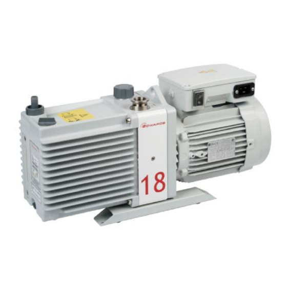
E1M18 and E2M18 Rotary
Vacuum Pumps
INSTRUCTION MANUAL
DESCRIPTION
E1M18, 100/200 V, 50 Hz or 100-105/200-210 V, 60 Hz, single-phase
E1M18, 115/230 V, 60 Hz, single-phase
E1M18, 220-240 V, 50 Hz, or 230-240 V, 60 Hz, single-phase
E1M18, 200-230/380-460 V, 50/60 Hz, three-phase
E1M18, 220-240 V, 50 Hz, or 230-240 V, 60 Hz, single-phase (Amphenol)
E1M18, 110/200-240 V, 50 Hz, or 115-120/200-230 V, 60 Hz, single-phase
E1M18, 110/200-240 V, 50 Hz, or 115-120/200-230 V, 60 Hz, single-phase, fomblin filled
E2M18, 100/200 V, 50 Hz or 100-105/200-210 V, 60 Hz, single-phase
E2M18, 115/230 V, 60 Hz, single-phase
E2M18, 220-240 V, 50 Hz, or 230-240 V, 60 Hz, single-phase
E2M18, 200-230/380-460 V, 50/60 Hz, three-phase
E2M18, 110/200-240 V, 50 Hz, or 115-120/200-230 V, 60 Hz, single-phase
E2M18-FF, 200-230/380-460 V, 50/60 Hz, three-phase
E2M18-FF, 100/200 V, 50/60 Hz, single-phase
E2M18, 220-240 V, 50 Hz, single-phase
E2M18, 110/200-240 V, 50 Hz, or 115-120/200-230 V, 60 Hz, single-phase, fomblin filled
A34310880_T
edwardsvacuum.com
ITEM NUMBER
A34315904
A34315981
A34315903
A34310940
A34316903
A34317984
A34325984
A36315904
A36315981
A36315903
A36310940
A36317984
A36321940
A36325904
A36325912
A36325984
Original instructions
Advertisement
Table of Contents

Related Manuals for Edwards E1M18


Summary of Contents for Edwards E1M18
- Page 1 E1M18, 220-240 V, 50 Hz, or 230-240 V, 60 Hz, single-phase (Amphenol) A34316903 E1M18, 110/200-240 V, 50 Hz, or 115-120/200-230 V, 60 Hz, single-phase A34317984 E1M18, 110/200-240 V, 50 Hz, or 115-120/200-230 V, 60 Hz, single-phase, fomblin filled A34325984 E2M18, 100/200 V, 50 Hz or 100-105/200-210 V, 60 Hz, single-phase A36315904...
- Page 2 EMF3, EMF10 and EMF20 oil mist filters A46226880 Trademark credit Edwards and the Edwards logo are trademarks of Edwards Limited, Innovation Drive, Burgess Hill, West Sussex RH15 9TW. Disclaimer The content of this manual may change from time to time without notice. We accept no liability for any errors that may appear in this manual nor do we make any expressed or implied warranties regarding the content.
- Page 3 RH15 9TW The following product AXXX - Pump type Variant Motor description 343 = E1M18 01 to 99 903 = 220V/240V 50/60Hz Single Phase 363 = E2M18 904 = 100V/200V 50/60Hz Single Phase 930 = 220V/240V 50/60Hz Single Phase 940 = 200-230V/380-460V 50/60Hz Three Phase...
- Page 4 Documentation Officer: Jelena Havelkova, Spielberk Office Centre, Holandska 10, Brno, 63900 Czech Republic, : +42(0) 734 418 896, : documentation@edwardsvacuum.com This declaration, based on the requirements of the listed Directives and EN ISO/IEC 17050-1, covers all product serial numbers from this date on: 21 May 2020.
- Page 5 Additional Legislation and Compliance Information EU RoHS Directive: Material Exemption Information This product is compliant with the following Annex III Exemptions 6(b) Lead as an alloying element in aluminium containing up to 0.4% by weight • 6(c) Copper alloy containing up to 4% lead by weight •...
- Page 6 This page has been intentionally left blank.
-
Page 7: Table Of Contents
Contents 1. Safety and compliance........7 1.1 Definition of Warnings and Cautions. - Page 8 5.2 Gas-ballast control..........32 5.3 Start-up.
- Page 9 10.2.8 Vibration isolators........48 10.2.9 Oil drain extension.
- Page 10 List of Figures Figure 1: General view of the pump..........11 Figure 2: Single-phase motors: Dimensions mm (inches).
-
Page 11: Safety And Compliance
A34310880_T - Safety and compliance 1. Safety and compliance 1.1 Definition of Warnings and Cautions NOTICE: This manual meets our obligation to provide you with information. For safe operation from the start, read these instructions carefully before you install or commission the equipment. - Page 12 A34310880_T - Safety and compliance Warning - refer to accompanying documentation. Warning - risk of electric shock. Warning - hot surfaces. Warning - do not block the pump outlet Warning - use protective equipment. Indicates that protective equipment must be used. Page 8...
-
Page 13: Introduction
A34310880_T - Introduction 2. Introduction 2.1 Scope and definitions This manual provides installation, operation and maintenance instructions for our rotary vacuum pumps. The pump must be used as specified in this manual. Read this manual before installing and operating the pump. 2.2 ATEX directive implications This equipment is designed to meet the requirements of Group II Category 3 equipment in accordance with Directive 2014/34/EU of the European Parliament and the Council of... - Page 14 A34310880_T - Introduction The E1M18 and E2M18 pumps are direct drive, sliding vane pumps. The E1M18 is a single-stage pump and the E2M18 is a two-stage pump. The pump is oil-sealed and designed for reliable, long-term operation in both laboratory and industrial environments.
-
Page 15: Gas-Ballast
A34310880_T - Introduction Figure 1 General view of the pump 1. Oil filler 1. Oil filler 2. Outlet nozzle 2. Outlet nozzle 3. Gas-ballast control 3. Gas-ballast control 4. Gas-ballast inlet 4. Gas-ballast inlet 5. Centring-ring and O-ring (supplied) 5. Centring-ring and O-ring (supplied) 6. - Page 16 A34310880_T - Introduction The gas-ballast control is a multi-turn valve: ▪ From the closed position, the first two turns of the gas-ballast control provide an additional oil-feed to the pump mechanism, but do not introduce gas-ballast into the pump. The additional oil-feed improves the lubrication and sealing of the pump mechanism.
-
Page 17: Technical Data
Pneurop standards. Table 2 Performance data Data Parameter E1M18 E2M18 Maximum displacement 50 Hz electrical supply 20.5 m 20.5 m 60 Hz electrical supply 25.0 m... -
Page 18: Mechanical Data
(for full pump throughout) 1.5 x 10 1.5 x 10 3.3 Mechanical data Table 3 Mechanical data Approximate pump mass 38 kg (E1M18), 41 kg (E2M18) Dimensions Refer to Figure: Dimensions (mm) on page 15 Degree of protection Single-phase motors... -
Page 19: Figure 2 Single-Phase Motors: Dimensions Mm (Inches)
A34310880_T - Technical data Figure 2 Single-phase motors: Dimensions mm (inches) 12 (0.72) 234 (9.21) - E1M18 282 (11.10) - E2M18 10 (0.39) 260 (10.24) 75 (2.95) 172 (6.77) 83 (3.27) - E1M18 131 (5.16) - E2M18 159 (6.26) - E1M18 207 (8.15) - E2M18... -
Page 20: Lubrication Data
A34310880_T - Technical data Figure 3 Three-phase motors: Dimensions mm (inches) 162 (6.38) 75 (2.95) 172 (6.77) 159 (6.26) - E1M18 207 (8.15) - E2M18 27 (1.06) Dimensions (mm) Pump item number Three-phase motors A34310940 50/60 A36310940 50/60 3.4 Lubrication data... -
Page 21: Electrical Data
A34310880_T - Technical data E2M18 1.05 litres * To operate the pump when the ambient temperature is outside the range specified in Operating and storage conditions on page 13 or to optimise pump performance when processing condensible vapours, a different oil may be required. 3.5 Electrical data Refer to Table: Electrical data: three-phase motors on page 17... - Page 22 A34310880_T - Technical data Voltage Frequency Pump item number Full load current (A) (Hz) A34317984, A36317984, 11.0 A34325984, A36325984 115 - 120 10.0 200 - 240 200 - 230 A34315912, A36315912 220 - 240 A34315920, A36315920 Motor output rating (continuous) 50 Hz operation 0.55 kW or 0.65 kW 60 Hz operation...
-
Page 23: Installation
A34310880_T - Installation 4. Installation 4.1 Safety WARNING: Ensure that the installation technician is familiar with the safety procedures which relate to the pump oil and the products handled by the pumping system. WARNING: If a hydrocarbon oil is used in this pump, do not use the pump to process oxygen in concentrations greater than 25% in volume. -
Page 24: Unpack And Inspect
Storage on page Table 9 Checklist of items Quantity Description Check ( ü ) E1M18 or E2M18 rotary vacuum pump Fitting pack containing the following: NW25 centring-ring O-ring for centring-ring Receptacle connectors* * Various sizes: supplied with single-phase motors except for pumps with Item numbers A34316903, A34317984, A36317984, A34325984 and A36325984. -
Page 25: Fill The Pump With Oil
A34310880_T - Installation For the locations of the fixing holes in the box section skids refer to Figure: Dimensions (mm) on page Provide a firm, level platform for the pump. Locate the pump so that the oil-level sight‑glass is visible and the oil filler-plug, oil drain-plugs and gas -ballast control are accessible. -
Page 26: Standard Single-Phase Motors
A34310880_T - Installation The diameter of the outer sheath of the electrical supply cable must be within the range 7 mm to 10.5 mm. The cable must conform in size and colour coding with the local and national electrical installation regulations. The temperature rating of the cable must be 70 °C or greater. -
Page 27: Amphenol Version Single-Phase Motors
A34310880_T - Installation ▪ Figure: Single-phase motors: 100 V 50 Hz, 100-105 V 60 Hz and 115 V 60 Hz on page 24 ▪ Figure: Single-phase motors: 200 V 50 Hz, 200-210 V 60 Hz and 230 V 60 Hz on page Tighten the earth (ground) terminal connection to a torque of 2.13 Nm to 2.8 Nm. -
Page 28: Figure 4 Single-Phase Motors: 220-240 V 50 Hz And 230-240 V 60 Hz
A34310880_T - Installation Figure 4 Single-phase motors: 220-240 V 50 Hz and 230-240 V 60 Hz Figure 5 Single-phase motors: 100 V 50 Hz, 100-105 V 60 Hz and 115 V 60 Hz Wire colour codes: Brown Violet Grey White Orange Page 24... -
Page 29: Figure 6 Single-Phase Motors: 200 V 50 Hz, 200-210 V 60 Hz And 230 V 60 Hz
A34310880_T - Installation Figure 6 Single-phase motors: 200 V 50 Hz, 200-210 V 60 Hz and 230 V 60 Hz Wire colour codes: Brown Violet Grey White Orange Figure 7 Single-phase motors with Amphenol connector: 220-240 V 50 Hz and 230-240 V 60 Hz Pin codes: Live Neutral... -
Page 30: Electrical Installation: Three-Phase Motors
A34310880_T - Installation Figure 8 Motor voltage selection: single-phase motors, 110/200-240 V 50 Hz and 115-120/200-240 V 60 Hz A. Top view of motor A. Top view of motor B. Internal view of top of motor B. Internal view of top of motor C. -
Page 31: Check The Direction Of Rotation
A34310880_T - Installation We recommend that you connect the electrical supply to the motor through a starter or circuit breaker which has thermal over‑current protection which can be adjusted to suit the full load current ratings shown in Table: Electrical data: three-phase motors on page 17. -
Page 32: Connect The Pump Inlet
A34310880_T - Installation ▪ Check the direction of rotation again. 4.8 Connect the pump inlet Take note of the following information when connecting the pump to the vacuum system. Refer to Accessories on page 46 for details of the accessories mentioned below. ▪... -
Page 33: Connect The Pump Outlet
A34310880_T - Installation Figure 10 Electrical supply connection, three-phase motors: 380-415 V 50 Hz and 460 V 60 Hz 4.9 Connect the pump outlet WARNING: Connect the pump outlet to a suitable treatment plant to prevent the discharge of dangerous gases and vapours to the surrounding atmosphere. Use a catchpot to prevent the drainage of contaminated condensate back into the pump. -
Page 34: Leak-Test The System
A34310880_T - Installation gas-ballast filter on page 40) to trap any dust and debris if air is used as the gas-ballast supply. If using a different gas for the gas-ballast supply or to connect a valve to the gas-ballast inlet: Remove the filters (as described in Clean the gas-ballast filter on page 39). -
Page 35: Operation
A34310880_T - Operation 5. Operation WARNING: Do not expose any part of the human body to vacuum. Failure to obey this warning could result in injury. Note: If the pump is PFPE-prepared, refer to PFPE-prepared EM pumps on page 5.1 ATEX directive implications This equipment is designed to meet the requirements of Group II Category 3 equipment in accordance with Directive 2014/34/EU of the European Parliament and the Council of 26th February 2014 on the approximation of the laws of the Member States concerning... -
Page 36: Gas Purges
A34310880_T - Operation ▪ Use an inert gas purge into the pump gas ballast connection to prevent the condensation of flammable vapours within the pump mechanism and exhaust pipeline. 5.1.2 Gas purges WARNING: If using inert gas purges to dilute dangerous gases to a safe level, ensure that the pump is shut down if an inert gas supply fails. -
Page 37: Start-Up
A34310880_T - Operation Turn the gas-ballast control from two to six turns anti-clockwise to increase the gas- ballast from zero flow. Use gas-ballast flow: ▪ To pump high concentrations of condensable vapour. ▪ To decontaminate the oil. When operating the pump with the gas-ballast control open there will be an increased rate of oil loss from the pump. -
Page 38: To Pump Condensable Vapours
A34310880_T - Operation ▪ Use of an oil other than the recommended oil and the vapour pressure of the oil is higher than the specified ultimate vacuum of the pump. Use the following procedure to achieve ultimate vacuum: Isolate the pump from the vacuum system. Turn the gas-ballast control fully anti-clockwise (fully open) and operate the pump for at least 1 hour (or overnight) to thoroughly purge the oil of contaminants. -
Page 39: Shut-Down
A34310880_T - Operation When checking the pump, make sure that the pump is not going through a repetitive cycle of thermal overload failures and automatic resets. If necessary, reduce the thermal load from the pumped gases to prevent overheating of the pump. 5.8 Shut-down Note: If the gas-ballast control is open and the motor is switched off for any reason, the pump... -
Page 40: Maintenance
A34310880_T - Maintenance 6. Maintenance 6.1 Safety information WARNING: Allow the pump to cool (so that it is at a safe temperature for skin contact) before starting maintenance work. Make sure the pump is switched off in case the thermal overload device restarts the pump. -
Page 41: Maintenance Plan
A34310880_T - Maintenance 6.2 Maintenance plan The plan shown in Table: Maintenance plan on page 37 details the routine maintenance operations necessary to maintain the pump in normal use. Instructions for each operation are given in the section shown. More frequent maintenance may be required if the pump is used to process corrosive or abrasive gases and vapours, in these circumstances, we recommend you to replace the pump seals every year. -
Page 42: Replace The Oil
A34310880_T - Maintenance Check that the oil‑level in the oil sight‑glass is between the MAX and MIN level marks on the bezel of the oil sight‑glass. If the oil‑level is near to or below the MIN level mark, remove the oil filler-plug and pour more oil into the reservoir until the oil reaches the MAX level mark. -
Page 43: Clean The Gas-Ballast Filter
A34310880_T - Maintenance Figure 11 Remove/replace the inlet filter 1. Inlet adaptor 1. Inlet adaptor 2. O-ring 2. O-ring 3. Circlip 3. Circlip 4. Inlet-filter 4. Inlet-filter 6.6 Clean the gas-ballast filter Note: The gas-ballast filter may have been removed to connect a gas supply or valve to the gas-ballast inlet. -
Page 44: Clean The Motor Fan-Cover And Enclosure
A34310880_T - Maintenance Figure 12 Remove/replace the gas-ballast filter 1. Filter element 1. Filter element 2. Wire mesh 2. Wire mesh 3. Retainer circlip 3. Retainer circlip 6.7 Clean the motor fan-cover and enclosure If the motor fan-cover and enclosure are not kept clean, the air flow over the motor can be restricted and the pump may overheat. -
Page 45: Fault Finding
A34310880_T - Fault finding 7. Fault finding A list of fault conditions and their possible causes is provided in the following sections to assist in basic fault-finding. If unable to rectify a fault when using this guide, call the supplier or our nearest service centre for advice. 7.1 The pump has failed to start ▪... -
Page 46: The Pump Surface Temperature Is Above 100 °C
A34310880_T - Fault finding 7.4 The pump surface temperature is above 100 °C ▪ The ambient temperature is too high. ▪ The cooling-air supply is insufficient or is too hot. ▪ The cooling-air supply is blocked. ▪ The electrical supply voltage is too high. ▪... -
Page 47: Storage
A34310880_T - Storage 8. Storage CAUTION: Observe the storage temperature limits stated in Technical data on page 13. Storage below - 30 °C will permanently damage the pump seals. Note: If you will store a new pump in conditions of high humidity, remove the pump from its cardboard packaging box, dispose of the box (refer to Disposal on page 44). -
Page 48: Disposal
A34310880_T - Disposal 9. Disposal Dispose of the pump, the oil and any components removed from the pump safely in accordance with all local and national safety and environmental requirements. Particular care must be taken with components and waste oil which have been contaminated with dangerous process substances. -
Page 49: Spares And Accessories
Table 11 Spares item numbers Spare Item Number Clean and Overhaul kit (Hydrocarbon filled) A36301131 Clean and Overhaul kit (PFPE filled) A36301136 E1M18 Blade kit A34301041 E2M18 Blade kit A36301020 Ultragrade 19 Oil (4 litres) H11025013 Fomblin Grade 06/6-500 ml... -
Page 50: Accessories
A34310880_T - Spares and accessories Spare Item Number Capacitor kit for pump part number A34317984 A50591814 Capacitor kit for pump part number A34325984 A50591814 Capacitor kit for pump part number A36317984 A50591814 Capacitor kit for pump part number A36325984 A50591814 10.2 Accessories A range of accessories is available for the pumps, as shown in Figure: Accessories on... -
Page 51: Inlet Catchpot
A34310880_T - Spares and accessories Table 12 Accessory item numbers Accessory Item number ITO20K Inlet catchpot A44110000 ITF20K Inlet dust filter A44215000 ITD20K Inlet desiccant trap A44510000 ITC20K Inlet chemical trap A44410000 EMF20 Outlet mist filter A46229000 PV25EK Valve: 200/240 V, 1-phase, 50/60 C41301000 PV25EK Valve: 110/127 V, 1-phase, 50/60 C41303000... -
Page 52: Solenoid Operated Pipeline Valve
A34310880_T - Spares and accessories 10.2.6 Solenoid operated pipeline valve Fit the pipeline valve between the vacuum system and the pump inlet to provide additional system protection when the pump is switched off. 10.2.7 Foreline trap Use a foreline trap on a clean pumping system to prevent back-migration of rotary pump oil vapour into the vacuum system. - Page 53 A34310880_T - PFPE-prepared EM pumps 11. PFPE-prepared EM pumps If a PFPE-prepared EM pump has been ordered, the pump will be supplied prepared for use with the manufacturers PFPE mechanical pump oils, such as Fomblin YVAC 06/6 and Krytox 1506. PFPE-prepared EM pumps are suitable for pumping high concentrations of oxygen.
- Page 54 A34310880_T - PFPE-prepared EM pumps ▪ When filling the PFPE-prepared EM pump with Fomblin oil, we recommend regular checks for oil leaks, particularly around the shaft seals. ▪ If an oil leak is detected, contact us or the supplier for advice. Page 50...
- Page 55 A34310880_T - Service 12. Service Our products are supported by a world‑wide network of our service centres. Each service centre offers a wide range of options including equipment decontamination, service exchange, repair, rebuild and testing to factory specifications. Equipment which has been serviced, repaired or rebuilt is returned with a full warranty.
- Page 56 edwardsvacuum.com...
Need help?
Do you have a question about the E1M18 and is the answer not in the manual?
Questions and answers