Table of Contents
Advertisement
Advertisement
Table of Contents

Related Manuals for Edwards E-LAB 2


Summary of Contents for Edwards E-LAB 2
- Page 1 Issue D Original Instruction Manual E-LAB 2 Pumps Description Item Number E-LAB 2 Pump, 110-120/220-240 V, 50/60 Hz, single phase A652-07-903 E-LAB 2 Pump, 100/200 V, 50/60 Hz, single phase A652-07-904 E-LAB 2 Pump, 110-120 V, 50/60 Hz, single phase...
- Page 2 West Sussex, RH15 9TW, UK declare under our sole responsibility, as manufacturer and person within the EU authorised to assemble the technical file, that the product(s) E-LAB 2 Rotary Vacuum Pumps: A652-07-903 A652-07-904 A652-07-906 to which this declaration relates is in conformity with the following standard(s) or other...
-
Page 3: Table Of Contents
Check the installation of the assembly ................27 5.8.2 Unblock the restrictor (if necessary) ................27 5.8.3 Unblock the air intake (if necessary) ................27 © Edwards Limited 2014. All rights reserved. Page i Edwards and the Edwards logo are trade marks of Edwards Limited. - Page 4 Service ........................35 Spares available ......................35 For return of equipment, complete the HS Forms at the end of this manual. Page ii © Edwards Limited 2014. All rights reserved. Edwards and the Edwards logo are trade marks of Edwards Limited.
- Page 5 Recommended time switch settings ................. 20 Maintenance plan .......................22 Associated publications Publication title Publication number Vacuum pump and vacuum system safety P300–20–000 © Edwards Limited 2014. All rights reserved. Page iii Edwards and the Edwards logo are trade marks of Edwards Limited.
- Page 6 A652–07–880 Issue D This page has been intentionally left blank. Page iv © Edwards Limited 2014. All rights reserved. Edwards and the Edwards logo are trade marks of Edwards Limited.
-
Page 7: Introduction
This manual provides installation, operation and maintenance instructions for the Edwards E-LAB 2 Pump (abbreviated to E-LAB 2 in the remainder of this manual). The pump must be used as specified in this manual. Read this manual before installing and operating the pump. -
Page 8: Description
E-LAB 2 to pump high-vapour loads. If required, the gas ballast flow rate into the pump can be reduced or switched off. When the E-LAB 2 is switched off, an inlet valve seals the inlet and prevents the suck-back of air and oil into the vacuum system. -
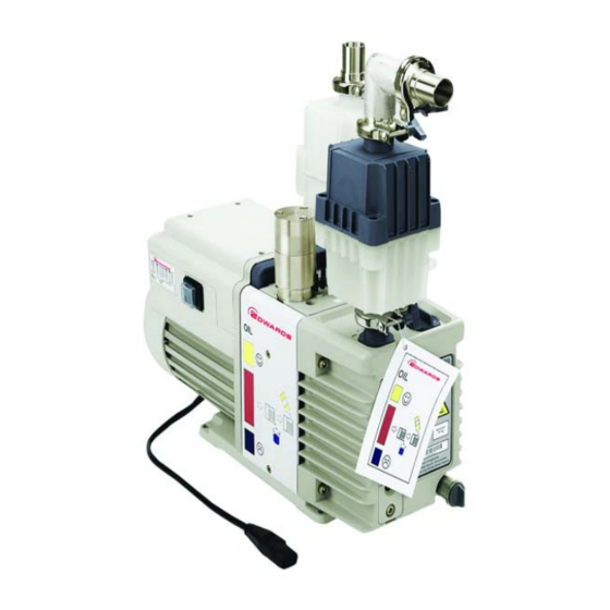
Page 9: The E-Lab 2 Pump
14. Correct direction of rotation 7. Oil filler-plugs 15. Lifting handle 8. Oil level sight glass 16. Gas ballast oil return assembly © Edwards Limited 2014. All rights reserved. Page 3 Edwards and the Edwards logo are trade marks of Edwards Limited. - Page 10 A652–07–880 Issue D This page has been intentionally left blank. Page 4 © Edwards Limited 2014. All rights reserved. Edwards and the Edwards logo are trade marks of Edwards Limited.
-
Page 11: Technical Data
-30 to 70 °C Maximum altitude (operation) 2000 m Pollution degree Installation category Performance Note: The pumping speed curves for the E-LAB 2 are shown in Figure 2 Suckback protection 1 x 10 mbar.ls , 1 x 10 Pa.ls Maximum displacement 50 Hz electrical supply 3.7 m... -
Page 12: Mechanical Data
Maximum mass of pump * 25.0 kg * Without pump oil, inlet catchpot, outlet mist filter, and gas ballast oil return kit. Page 6 © Edwards Limited 2014. All rights reserved. Edwards and the Edwards logo are trade marks of Edwards Limited. -
Page 13: Noise And Vibration Data
Within five minutes, as the oil in the pump warms up, the current drawn will slowly reduce to the full load current specified in Tables 1and 2. © Edwards Limited 2014. All rights reserved. Page 7 Edwards and the Edwards logo are trade marks of Edwards Limited. -
Page 14: Lubrication Data
0.70 l Minimum 0.42 l To operate the E-LAB 2 when the ambient temperature is outside the limits specified in Section 2.1, a different oil may be required. Materials of construction The surfaces of the pump that are exposed to the process vapours pumped are free from copper, zinc and cadmium. -
Page 15: Installation
WARNING Do not expose any part of the human body to vacuum as it can cause injury. Ensure that the pump is suitable for the application. If there is any doubt, refer to the Edwards guidelines in the Vacuum Pump and Vacuum Systems Safety manual. (See Associated publications at the end of the Content list.) -
Page 16: Unpack And Inspect
Locate the pump The E-LAB 2 has a lifting handle that can be used to move the pump by hand. If using mechanical lifting equipment, do not attach the equipment to the handle; for stability, use slings around the motor and the pump body. -
Page 17: Fill The Pump With Oil
7. Fit the other end of the tube to the nozzle (4) on the oil return assembly (5). 8. Use the hose clips (2) to secure the ends of the flexible oil-return tube (3). © Edwards Limited 2014. All rights reserved. Page 11 Edwards and the Edwards logo are trade marks of Edwards Limited. -
Page 18: Fit The Inlet Trap And Oil Mist Filter
25. Inlet catchpot inlet 8. Elbow 17. Pump outlet 26. Clamping ring 9. Co-Seal 18. Gas ballast control 27. O-ring and centring ring Page 12 © Edwards Limited 2014. All rights reserved. Edwards and the Edwards logo are trade marks of Edwards Limited. - Page 19 2. Hose clip 6. E-LAB 2 pump B. Top view 3. Flexible oil-return tube 7. Restrictor 4. Nozzle 8. Drain adaptor © Edwards Limited 2014. All rights reserved. Page 13 Edwards and the Edwards logo are trade marks of Edwards Limited.
-
Page 20: Select The Gas Ballast Flow Rate (Optional)
Select the gas ballast flow rate (optional) Note: Use the procedure below to change the gas ballast flow rate after the E-LAB 2 has been used. The pump must be switched off, allowed to cool and isolated from the electrical supply before doing the following procedure. -
Page 21: Fit The Inlet Catchpot
3. Invert the voltage selector switch cover (5) and refit over the voltage selector switch (3). 4. Refit the two retaining screws (6). © Edwards Limited 2014. All rights reserved. Page 15 Edwards and the Edwards logo are trade marks of Edwards Limited. -
Page 22: Motor Voltage Configuration
3. Voltage selector switch 4. On/off switch 5. Voltage selector switch cover 6. Retaining screws 7. Position 'I' (on) 8. Position '0' (off) Page 16 © Edwards Limited 2014. All rights reserved. Edwards and the Edwards logo are trade marks of Edwards Limited. -
Page 23: Connect The Pump To The Electrical Supply
E-LAB 2 pumps with Item Numbers A652-07-904 and A652-07-906 are supplied with an electrical supply cable with a moulded IEC connector at one end, and with the other end of the cable fitted with a plug suitable for the local electrical supply. -
Page 24: Check The Direction Of Rotation
Leak test the system after installation is complete and seal any leaks found to prevent leakage of hazardous substances out of the system and leakage of air into the system. Page 18 © Edwards Limited 2014. All rights reserved. Edwards and the Edwards logo are trade marks of Edwards Limited. -
Page 25: Operation
Use the following procedure to achieve ultimate vacuum: 1. Isolate the E-LAB 2 from the vacuum system and operate the E-LAB 2 for at least 1 hour (or overnight) to thoroughly purge the oil of contaminants. -
Page 26: To Decontaminate The Oil
The overload device resets automatically when the motor has cooled. When checking the E-LAB 2, make sure that the pump is not going through a repetitive cycle of thermal overload failures and automatic resets. If necessary, reduce the thermal load from the pumped gases, to prevent overheating of the pump. -
Page 27: Maintenance
The pump may have overheated if it was misused or if it was in a fire. Safety Data sheets for fluorinated materials used in the pump are available on request: contact the supplier or Edwards. © Edwards Limited 2014. All rights reserved. -
Page 28: Maintenance Plan
If necessary, adjust the maintenance plan according to experience. When maintaining the E-LAB 2, use Edwards spares and maintenance kits; these contain all of the components necessary to complete maintenance operations successfully. The Item Numbers of the spares and kits are given in... -
Page 29: Check The Pump Oil Level
8. Allow a few minutes for the oil to drain into the pump. If necessary, add more oil. Refit the filler plug. © Edwards Limited 2014. All rights reserved. Page 23 Edwards and the Edwards logo are trade marks of Edwards Limited. -
Page 30: Inspect The Oil Mist Filter Elements
4, item 3) and the outlet (12) of the oil mist filter, then place the Co-Seal on the outlet. 8. Refit the elbow (4) to the outlet and secure with the clamping ring (2). Page 24 © Edwards Limited 2014. All rights reserved. Edwards and the Edwards logo are trade marks of Edwards Limited. -
Page 31: The Outlet Oil Mist Filter
13. Maximum oil level mark 4. Drain plug 9. ‘D’ seal 14. Sight panel 5. Mist filter element O-ring 10. Upper body (grey) © Edwards Limited 2014. All rights reserved. Page 25 Edwards and the Edwards logo are trade marks of Edwards Limited. -
Page 32: Inspect And Clean The Pump Inlet-Filter
4, item 24) to the pump inlet (19) and secure with the clamping ring (20). Figure 9 - Pump inlet filter assembly 1. Centring ring and filter assembly 2. O-ring 3. Pump inlet Page 26 © Edwards Limited 2014. All rights reserved. Edwards and the Edwards logo are trade marks of Edwards Limited. -
Page 33: Inspect The Oil Return Assembly
4. Refit the top piece (3) to the oil return assembly and secure with the three screws (1), then reconnect the pump to the electrical supply. © Edwards Limited 2014. All rights reserved. Page 27 Edwards and the Edwards logo are trade marks of Edwards Limited. -
Page 34: Clean The Pump Oil Level Sight Glass
Figure 10 - Sight glass assembly 1. Screws (2 off M6 x 20) 4. O-ring 2. Bezel 5. Oil box 3. Sight glass Page 28 © Edwards Limited 2014. All rights reserved. Edwards and the Edwards logo are trade marks of Edwards Limited. -
Page 35: Part Sectional View Of The Oil Return Assembly
Figure 11 - Part sectional view of the oil return assembly 1. Screw 4. Expansion chamber 2. Air intake 5. Silencer tube 3. Restrictor plate © Edwards Limited 2014. All rights reserved. Page 29 Edwards and the Edwards logo are trade marks of Edwards Limited. -
Page 36: Clean The Motor Fan Cover
The motor of the E-LAB 2 complies with IEC 1010-1. We recommend that, to maintain compliance with IEC 1010-1, the earth continuity is less than 0.1Ω and the insulation resistance is greater than 10 MΩ. -
Page 37: Fault Finding
Fault finding A list of fault conditions and their possible causes is provided here to assist in fault finding. If a fault cannot be rectified when using this guide, call the nearest Edwards Service Centre for help. 5.14.1 The pump has failed to start The electrical supply fuse has blown ... -
Page 38: The Pump Surface Temperature Is Above 100 °C
There is an oil leak from the drain plug There is an oil leak from the sight glass. Page 32 © Edwards Limited 2014. All rights reserved. Edwards and the Edwards logo are trade marks of Edwards Limited. -
Page 39: Storage And Disposal
Particular care must be taken with components and waste oil which have been contaminated with dangerous process substances. Do not incinerate fluoroelastomer seals and O-rings. © Edwards Limited 2014. All rights reserved. Page 33 Edwards and the Edwards logo are trade marks of Edwards Limited. - Page 40 A652–07–880 Issue D This page has been intentionally left blank. Page 34 © Edwards Limited 2014. All rights reserved. Edwards and the Edwards logo are trade marks of Edwards Limited.
-
Page 41: Service And Spares
The majority of these centres employ Service Engineers who have undergone comprehensive Edwards training courses. Order spare parts and accessories from the nearest Edwards company or distributor. When ordering, state for each part required: Model and Item Number of the equipment ... - Page 42 A652–07–880 Issue D This page has been intentionally left blank. Page 36 © Edwards Limited 2014. All rights reserved. Edwards and the Edwards logo are trade marks of Edwards Limited.
Need help?
Do you have a question about the E-LAB 2 and is the answer not in the manual?
Questions and answers