Table of Contents
Advertisement
Advertisement
Table of Contents

Related Manuals for Edwards E1M8


Summary of Contents for Edwards E1M8
- Page 1 Instruction Manual Rotar y Vacuum Pum p s E2M2, E1/E2M5 and 8, E2M12 •• ll#EDWARDS � � Edwards High Vacuum International Manor Royal, Crawley, West Sussex RH10 2LW 1996 19113 Telephone: (01293) 528844 Fax: (01293) 533453 Telex: 87123 Edivac G...
- Page 2 Declaration of Conformity Edwards High Vacuum International, Manor Royal, Crawley, West Sussex RHlO 2LW, UK declare under our sole responsibility that the product(s) E2M2, E1M5, E2M5, E1M8, E2M8 and E2M12 Rotary Vacuum Pumps: A341-01-912 A342-01-912 A342-15-903 A360-01-912 A360-01-916 A360-01-981 A360-01-996...
-
Page 3: Table Of Contents
CONTENTS Section Title Page INTRODUCTION Scope of this manual Description Gas-ballast TECHNICAL DATA Operating and storage conditions Electrical data; single-phase motors Electrical data; three-phase motors Lubrication data Performance Mechanical data INSTALLATION Safety System design Unpack and inspect Locate the pump Fill the pump with oil Electrical installation: single-phase motors 3.6.1... -
Page 4: Title
Foreline trap 7.3.7 Solenoid operated pipeline valve 7.3.8 Outlet mist filter 7.3.9 Oil drain extension 7.3.10 Vibration isolators 7.3.11 Pump inlet adaptor 7.3.12 Flexible bellows 7.3.13 Pump outlet adaptor RETURN OF EDWARDS EQUIPMENT E2M2, E1/E2M5 and 8, E2M12 Rotary Vacuum Pumps... - Page 5 Illustrations Figure Title Page The E2M2 pump (single-phase motor shown) Dimensions E2M2 ElM/E2M5 and 8 (refer to Tables 1 and 2 for applicability ) (mm) Dimensions El/E2M8 (some single-phase pumps: refer to Table 1 for applicability) (mm) Dimensions E2M8 (some three-phase pumps only: refer to Table 2 for applicability) (mm) Dimensions E2M12 (some single-phase pumps: refer to Table 1 for applicability) (mm) Dimensions E2M12...
- Page 6 Tables Table Title Page Electrical and mechanical data, single-phase motors Electrical and mechanical data, three-phase motors Performance data Mechanical data Check list Maintenance plan Associated publications Publication title Publication number Vacuum Pump and Vacuum System Safety P300-20-000 E2M2, E1/E2M5 and 8, E2M12 Rotary Vacuum Pumps...
-
Page 7: Introduction
INTRODUCTION Scope of this manual This manual provides installation, operation and maintenance instructions for the Edwards E2M2, El/E2M5 and 8, and E2M12 rotary vacuum pumps. The item numbers for each pump are listed in Section 2. You must use the pump as specified in this manual. Read this manual before you install and operate the pump. -
Page 8: Electrical Cable Connection, Method
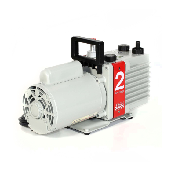
1. Outlet nozzle Cable gland 2. Oil filler-plug Overload reset button (single-phase 3. Gas-ballast control motors, where applicable) 4. NW25 inlet-port (adaptor flange) Baseplate 5. NW25 centring ring and 'O' ring (supplied) Oil drain-plug 6. On/Off switch (single-phase motors only) Oil sight-glass 7. -
Page 9: Description
Description The Edwards E2M2, El/E2M5 and 8, and E2M12 pumps are shown in Figure 1. Refer to Figure 1 for item numbers in brackets in the following descriptions. The E2M2, El/E2M5 and 8, and E2M12 pumps are single and two-stage, direct drive, sliding vane pumps. -
Page 10: Technical Data
Lubrication data Note: An Edwards Health and Safety Data Sheet for the following oil is available on request. Recommended oil* Ultragrade 19 Maximum oil capacity 0.6 litre (E1M5 or 8) - Page 11 t'r:1 � Auto (A) or � Full Electrical manual (M) load Start thermal supply connection Dimension Voltage Frequency current current Recommended overload Dimensions (Hz) (mm) Item Number fuse rating (A) reset Figure Figure Pump E" � 34.0 A360-01-996 449 131 17.0 (") ;:::...
- Page 12 °' Auto (A) or Full manual (M) Electrical Start thermal supply load Voltage Frequency current current Recommended overload connection Dimension Dimensions (Hz) Pump ItemNumber fuse rating (A) reset Im m ] E1M8 A342-01-912 220-240 29.5 448 153 A362-01-912 220-240 29.5 470 153 A362-05-912 220-240...
- Page 13 tT:1 "'"' � ;::, ;::! ;::,.. Full Electrical � load Start supply tT:1 Voltage Frequency current current Recommended connection Dimension Dimensions � "'"' (Hz) Item Number fuse rating (A) Figure Figure Pump (mm) � � 1.21 220-240 � A360-01-916 E2M2 �...
-
Page 14: Performance
� ElMS E2M2 E2M5 E1M8 E2M8 E2M12 "'d ..� � � Maximum displacement 9 .5 m 3 h- 1 5.6 m 3 h - l 5.6m 3 h - l 2.8 m 3 h- l 9 .5 m 3 h- l 14. -
Page 15: Mechanical Data
$::) � � i::,..� -?=> t'r1 � � 1---' ..� ::,;:i � i3" E2M2 E1M5 E2M5 E2M12 E1M8 E2M8 � 18.2 kg 16.8kg 19.6 kg 20kg 22.8 kg 26kg � Mass (approximate) ;::: ;::: Dimensions Refer to Tables 1 and 2 �... -
Page 16: Refer To Tables 1 And 2 For Applicability ) (Mm)
25 1 4x9 0 NW25 r-----, , ______ J Single-phase pumps only Some single-phase pumps only (refer to dimension C in Table 1) Figure 2 - Dimensions E2M2, ElM/E2M5 and 8 (refer to Tables 1 and 2 for applicability) (mm) E2M2, E1/E2M5 and 8, E2M12 Rota ry Vacuum Pumps... - Page 17 =kl� j� � � ·-- ro-1 �1 • - - � 2� 3� �� - � :� 1� 4x 9 0 ◄ Figure 3 - Dimensions ElM/E2M8 (some single-phase pumps: refer to Table 1 for applicability) (mm) 4x90 �� �,,�----==·--�:�,� t-==-' �...
-
Page 18: Dimensions E2M12 Some Single-Phase Pumps: Refer To Table 1 For Applicability) (Mm)
I � - --c-=--,- �I ,..,. __ --=2-=-3-=- 0 ----- ◄ ..,.1 ►f Single-phase pumps only 2. Some single-phase pumps only (refer to dimension C in Table 1) t_ _____ J Figure 5 - Dimensions E2M12 (some single-phase pumps: refer to Table 1 for applicability) (mm) �- -)t--,-----= ,_,_ ·-�... -
Page 19: Installation
You must ensure that the pump is suitable for your application, If you have any doubts as to the suitability of the pump for your application, refer to the Edwards guidelines on vacuum pump and vacuum system safety (see the Associated Publication at the end of the contents list at the front of this manual). -
Page 20: System Design
System design Consider the following points when you design your pumping system: • Use a suitable inlet-valve to isolate the pump from your vacuum system if you need to allow the pump to warm up before you pump condensable vapours or if you need to maintain vacuum when the pump is switched off. -
Page 21: Locate The Pump
Locate the pump WARNING Use suitable lifting equipment to move the pump. The mass of the pumps is approximately 17 kg to 26 kg. The pump can be either free-standing on its baseplate, or fixed by bolts through the four fixing holes in the baseplate, or used with vibration isolators. -
Page 22: Electrical Installation: Single-Phase Motors
Electrical installation: single-phase motors WARNING Ensure that the electrical installation of the pump conforms with your local and national safety requirements. It must be connected to a suitably fused and protected electrical supply and a suitable earth point. CAUTION If your pump-motor can be used with more than one voltage range, you must ensure that the motor is configured for your electrical supply voltage and frequency. -
Page 23: Electrical Cable Connection, Method 2
3.6.2 Electrical cable connection, method 2 If the electrical connection diagram for your pump is Figure 10 or 11, use this method to connect the electrical supply cable. 1. Remove the cover from the motor terminal box (Figure 1, item 8). 2. -
Page 24: Electrical Supply Connections, Single-Phase Motors, (High Voltage)
(" , .. - .. Wire colour codes: BK Black BU Blue BN Brown RD Red WHWhite YE Yellow 1. On/off switch 2. Manual reset button Figure 8 - Electrical supply connection, single-phase motors, (low voltage) (see Table 1 for applicability) N -at- L �... - Page 25 Wire colour codes: BN Brown OR Orange VT Viole < WHWhite Figure 10 - Electrical supply connection, single-phase motors, (low voltage) (see Table 1 for applicability) Wire colour codes: BN Brown OR Orange VT Violet WHWhite Figure 11 - Electrical supply connection, single-phase motors (high voltage) (see Table 1 for applicability) E2M2, El/E2M5 and 8, E2M12 Rotary Vacuum Pumps...
-
Page 26: Electrical Installation: Three-Phase Motors
Electrical installation: three-phase motors 3.7.1 Connect the pump to your electrical supply WARNING Ensure that the electrical installation of the pump conforms with your local and national safety requirements. It must be connected to a suitably fused and protected electrical supply and a suitable earth point. - Page 27 IT6 1 rv { � � - - - -,, 'I.. - - - -- Wire colour codes: IT91 BU Blue RD Red YE Yellow Figure 12 - Electrical supply connection, three-phase motors, (low voltage) (see Table 2 for applicability) IT11 �...
- Page 28 - - - -, .. 3 ,.._ , .., Wire colour codes: BK Black BN Brown BU Blue RD Red WHWhite YE Yellow Figure 14 - Electrical supply connection, three-phase motors (low voltage) (see Table 2 for applicability) l YE 'U 2 '\- - - - r, ...J...
- Page 29 ,----T"\ --tU 3 rv >.. ""'----l..l < � < Figure 16 - Electrical supply connection, three-phase motors, Gow voltage) 200-220 V 50 Hz, or 200-230 V 60 Hz 200 V 50/60 Hz, 220-240 V 50 Hz w2'o ,:.) -----7' 3 rv >-..
-
Page 30: Check The Direction Of Rotation
We recommend that you use Edwards flexible bellows. E2M2, El/E2MS and 8, E2M12 Rota ry Vacuum Pumps... -
Page 31: Outlet Connection
• Use a suitable catchpot you pump condensable vapours or you use the pump for very dusty applications. • Ensure that sealing surfaces are clean and scratch-free. Outlet connection WARNING Connect the pump outlet to a suitable treatment plant to prevent the discharge of dangerous gases and vapours to the surrounding atmosphere. -
Page 32: Gas Ballast Inlet Connection
3.10 Gas ballast inlet connection The position of the gas ballast inlet is shown in Figure 1 (item 3). The gas ballast inlet has several filters (shown in Figure 19) to trap any dust and debris if you use air as the gas ballast supply. If you want to use a different gas for the gas ballast supply, or if you want to connect a valve to the gas ballast inlet, remove the filters (as described in Section 5.6) and connect your gas supply or valve to the 1 / 4 inch BSP threaded hole. -
Page 33: Operation
OPERATION Gas-ballast control Use the gas-ballast control (Figure 1, item 3) to change the flow of gas-ballast into the low vacuum stage of the pump. Use the gas-ballast control closed: • to achieve ultimate vacuum • to pump dry gases. Tum the gas-ballast control 5 turns anti-clockwise to open it fully. -
Page 34: Re-Set The Thermal Overload Device
If the pump does not achieve the performance specified in Section 2, make sure that this is not due to your system design before you contact your supplier or Edwards for advice, In particular, the vapour pressure of all materials used in your vacuum system (including pump oil, see below) must be much lower than the specified ultimate vacuum of the pump. -
Page 35: To Pump Condensable Vapours
Tum the gas-ballast control fully anti-clockwise (fully open) and operate the pump for at least 1 hour (or overnight) to thoroughly purge the oil of contaminants. 3. Close the gas-ballast control. 4. Open the vacuum system isolation-valve and pump down to ultimate vacuum. To p um p condensable va p ours Use gas-ballast (open the gas-ballast control) when there is a high proportion of condensable vapours in the process gases. -
Page 36: Shut-Down
Single-phase motors are cooled by internal fans. These motors have either an automatic or manual reset thermal overload device. When the motor is too hot, the thermal overload device switches off the pump. If the thermal overload device has an automatic reset, when the pump cools down, the device resets and the pump will restart. -
Page 37: Maintenance
The pump may have overheated if it was misused, if it malfunctioned or if it was in a fire. Edwards Health and Safety Data sheets for fluorinated materials used in the pump are available on request: contact your supplier or Edwards. -
Page 38: Maintenance Plan
If necessary, adjust the maintenance plan according to your experience. When you maintain the pump, use Edwards spares and maintenance kits; these contain all of the components necessary to complete maintenance operations successfully. The Item Numbers of the spares and kits are given in Section 7. -
Page 39: Replace The Oil
Replace the oil Refer to Figure 1 for the items in brackets. Operate the pump for approximately ten minutes to warm the oil, then switch off the pump. (This lowers the viscosity of the oil and allows the oil to be drained from the pump more easily). -
Page 40: Clean The Gas-Ballast Filter
Inlet adaptor 'O' ring Circlip Inlet-filter Figure 18 - Inlet-filter removal and replacement (E2M2 illustrated) Clean the gas-ballast filter Refer to Figure 19. Unscrew and remove the gas-ballast control (1). Remove the filter element (2) from its position below the control. Wash the filter element in a suitable cleaning solution. -
Page 41: Clean The Motor Fan-Cover
1 . Gas-ballast control Filter element Figure 19 - Gas-ballast filter removal and replacement (E2M2 illustrated) Clean the motor fan-cover If the motor fan-cover is not kept clean, the air-flow over the motor can be restricted and the pump may overheat. 1. -
Page 42: Fault Finding
A list of fault conditions and their possible causes is provided here to assist you in basic fault-finding. If you are unable to rectify a fault when you use this guide, call your supplier or your nearest Edwards Service Centre for advice. 5.11.1 The pump has failed to start •... -
Page 43: The Pump Surface Temperature Is Above 100 °C
• The motor bearings are worn. • The oil is contaminated with solid particles. • One of the pump blades is sticking. 5.11.4 The pump surface temperature is above 100 °C. • The ambient temperature is too high • The cooling-air supply is insufficient or is too hot. •... -
Page 44: Storage And Disposal
STORAGE AND DISPOSAL Storage CAUTION Observe the storage temperature limits stated in Section 2. Storage below -30 °C will permanently damage the pump seals. Note: If you will store a new pump in conditions of high humidity, remove the pump from its cardboard packaging box;... -
Page 45: Sp Are And Accessories
Kingdom, U.S.A and a worldwide network of distributors. The majority of these centres employ Service Engineers who have undergone comprehensive Edwards training courses. Order spare parts and accessories from your nearest Edwards company or distributor. When you order, state for each part required: •... -
Page 46: Inlet Dust Filter
7.3.2 Inlet dust filter The inlet dust filter protects the pump against abrasive dust. Item Number Product ITF20K Inlet dust filter A442-15--000 7.3.3 Inlet desiccant trap Use a desiccant trap when you pump limited quantities of water vapour at high pumping speeds to a low vapour pressure. -
Page 47: Outlet Mist Filter
7.3.8 Outlet mist filter The outlet mist filter separates and traps oil droplets in the pump outlet to prevent oil mist discharge. Product Item Number EMFIO Outlet mist filter (E2M2, El/E2M5 and 8) A462-26-000 EMF20 Outlet mist filter (E2M12) A462-29-000 7.3.9 Oil drain extension Fit the oil drain extension between the oil drain port on the pump and the oil drain-plug to make... -
Page 48: Accessories
�---- ---- T ----- ---- ---� © -r-- ____ L-- - ? � . ��I ® .- - -- ____ J I ______ _, 1. Inlet catchpot 2. Inlet dust filter 3. Inlet desiccant trap 4. Inlet chemical trap 5. Solenoid operated gas-ballast valve 6.
Need help?
Do you have a question about the E1M8 and is the answer not in the manual?
Questions and answers