Edwards Drystar EDP80 Series Instruction Manual

Edwards Drystar EDP80 Series Instruction Manual

Chemical dry vacuum pumps
Table of Contents

Advertisement

Quick Links

EDP160 (50 Hz), EDP160 (60 Hz), EDP250 (50/60 Hz),
Description
Drystar EDP80 (50 Hz) Bareshaft Pump
Drystar EDP80 (60 Hz) Bareshaft Pump
Drystar EDP160 (50 Hz) Bareshaft Pump
Drystar EDP160 (60 Hz) Bareshaft Pump
Drystar EDP250 (50/60 Hz) Bareshaft Pump
Drystar EDP400 (50 Hz) Bareshaft Pump
Drystar EDP400 (60 Hz) Bareshaft Pump
Note:
The Item Numbers listed above are for Bareshaft Pumps, without a motor. However, this manual contains general information
on how to connect a motor to the electrical supply, and on how to replace a motor.
The EDP Pumping System instruction manual you will receive will define the build specification of your pump; that is, the
type of motor and any ordering options and accessories fitted. You will also receive a motor instruction manual specific to
the motor fitted to your pump.
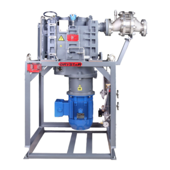
Instruction Manual
Drystar® EDP80 (50 Hz), EDP80 (60 Hz),
EDP400 (50 Hz) and EDP400 (60 Hz)
Chemical Dry Vacuum Pumps
A705-40-880
Issue B Original
Item Number
A705-45-000
A705-47-000
A705-44-000
A705-46-000
A705-43-000
A705-42-000
A705-41-000

Advertisement

Table of Contents
loading

Summary of Contents for Edwards Drystar EDP80 Series

  • Page 1 A705-40-880 Issue B Original Instruction Manual Drystar® EDP80 (50 Hz), EDP80 (60 Hz), EDP160 (50 Hz), EDP160 (60 Hz), EDP250 (50/60 Hz), EDP400 (50 Hz) and EDP400 (60 Hz) Chemical Dry Vacuum Pumps Description Item Number Drystar EDP80 (50 Hz) Bareshaft Pump A705-45-000 Drystar EDP80 (60 Hz) Bareshaft Pump A705-47-000...
  • Page 2 The relevant technical documentation has been compiled in accordance with Annex VII Part B. In response to a reasoned request by the national authorities, Edwards Ltd undertakes to provide relevant information on the partly completed machinery (via email).
  • Page 3: Table Of Contents

    Connect the pump-inlet to your process system ..............27 3.10.2 Connect the pump-outlet to your exhaust system ..............28 3.11 Leak test the installation ....................28 © Edwards Limited 2011. All rights reserved. Page i Edwards and the Edwards logo are trademarks of Edwards Limited.
  • Page 4 Remove the drive hub and fit to the new pump-motor (pumps without a torque limiter) ....56 5.15.6 Remove the torque limiter and fit to the new pump-motor (pumps with a torque limiter) ....56 Page ii © Edwards Limited 2011. All rights reserved. Edwards and the Edwards logo are trademarks of Edwards Limited.
  • Page 5 Exploded view of the pump-motor, coupling drive and coupling cover (pumps without a torque limiter) 61 Use the motor change frame to lower the pump-motor and coupling cover assembly ......62 Remove/refit the service module ..................67 © Edwards Limited 2011. All rights reserved. Page iii Edwards and the Edwards logo are trademarks of Edwards Limited.
  • Page 6 Fault finding ......................68 Spares and maintenance kits ..................74 Trademark credits ® Drystar is a registered trademark of the Edwards group plc. Page iv © Edwards Limited 2011. All rights reserved. Edwards and the Edwards logo are trademarks of Edwards Limited.
  • Page 7: Introduction

    Introduction Scope and definitions This manual provides installation, operation and maintenance instructions for the Edwards Drystar EDP80, EDP160, EDP250 and EDP400 Chemical Dry Vacuum Pumps. You must use the EDP pumps as specified in this manual. Read this manual before you install and operate your pump. Important safety information is highlighted as WARNING and CAUTION instructions;...
  • Page 8: Shaft-Seals Purge

    EDP pump will be fitted with one of the following: A temperature transmitter.  A thermal snap-switch  Refer to Section 3.6.4 3.6.5 for connection details. Non-ATEX systems only. Page 2 © Edwards Limited 2011. All rights reserved. Edwards and the Edwards logo are trademarks of Edwards Limited.
  • Page 9: Pressure Relief Valve (Edp250 And Edp400 Only)

    When the torque limiter trips, the pump-motor will continue to operate, however there will be a significant fall in the electrical current consumed by the pump-motor. © Edwards Limited 2011. All rights reserved. Page 3 Edwards and the Edwards logo are trademarks of Edwards Limited.
  • Page 10: Pump Frame

    Fixing holes (9) in the frame can be used to secure the pump frame in its operating position. Page 4 © Edwards Limited 2011. All rights reserved. Edwards and the Edwards logo are trademarks of Edwards Limited.
  • Page 11: The Edp Pump: Sheet 1 Of 2

    19. Service module lifting bolts 10. Direction of rotation arrow A temperature transmitter may be fitted instead of a thermal snap-switch: see Section 1.4. © Edwards Limited 2011. All rights reserved. Page 5 Edwards and the Edwards logo are trademarks of Edwards Limited.
  • Page 12 21. Bleed plug (EDP80/EDP160 only) 25. Pump-outlet 22. Heat exchanger 26. Pressure relief valve (EDP250/EDP400 only) 23. Pump-motor terminal-box 27. Pump case temperature measurement point Page 6 © Edwards Limited 2011. All rights reserved. Edwards and the Edwards logo are trademarks of Edwards Limited.
  • Page 13: Pump Motor Applicability

    The use of approved flame arrestors is mandatory for some ATEX system classifications. Refer to the ATEX  System instruction manual for more information. © Edwards Limited 2011. All rights reserved. Page 7 Edwards and the Edwards logo are trademarks of Edwards Limited.
  • Page 14: Abnormal Operation

    Use of the EDP pump in a potentially explosive external atmosphere, unless the pumping system is certified  as compliant with ATEX Directive 94/9/EC (European Union only). Page 8 © Edwards Limited 2011. All rights reserved. Edwards and the Edwards logo are trademarks of Edwards Limited.
  • Page 15: Technical Data

    1.15 1.15 1.15 outlet 1.3x10 1.3x10 1.15x10 1.3x10 1.15x10 1.3x10 1.15x10 1.15x10 pressure: psi g bar abs 1.3x10 1.3x10 psi g © Edwards Limited 2011. All rights reserved. Page 9 Edwards and the Edwards logo are trademarks of Edwards Limited.
  • Page 16: Mechanical Data

    Table 5 - Shaft-seals purge nitrogen supply data Minimum Maximum Supply pressure bar g 2.00 3x10 1.1x10 psi g Regulated pressure to shaft-seals 3x10 5x10 psi g Page 10 © Edwards Limited 2011. All rights reserved. Edwards and the Edwards logo are trademarks of Edwards Limited.
  • Page 17: Temperature Control System

    40 US 72 US 72 US 72 US 72 US 84 US 84 US gal/h gal/h gal/h gal/h gal/h gal/h gal/h gal/h © Edwards Limited 2011. All rights reserved. Page 11 Edwards and the Edwards logo are trademarks of Edwards Limited.
  • Page 18: Coolant Type

    A705-40-880 Issue B Coolant type The pump is supplied filled with Edwards coolant which is monopropylene based, and is both an antifreeze and a corrosion inhibitor. Spare Edwards coolant is available: refer to Section 7.3. If you will use another coolant type to replenish lost coolant: It must prevent the formation of visible oxide sludge and scale deposits.
  • Page 19: Connections

    1/2 inch NPT female Middle-stage and gas-ballast purge port fittings type EDP80 1/4 inch BSP EDP160, EDP250, EDP400 1/2 inch BSP © Edwards Limited 2011. All rights reserved. Page 13 Edwards and the Edwards logo are trademarks of Edwards Limited.
  • Page 20: Edp Pump Dimensions: Mm (Sheet 1 Of 2)

    2. Pump-outlet 3. Fixing hole: Ø18 mm (4 off) 4. Cooling-water outlet connection 5. Cooling-water inlet connection 6. Nitrogen supply inlet connection Page 14 © Edwards Limited 2011. All rights reserved. Edwards and the Edwards logo are trademarks of Edwards Limited.
  • Page 21 EDP160 EDP250 50 Hz 60 Hz 1423 1458 1681 1730 1721 1254 1289 1514 1562 1549 1148 1148 1149 1000 1000 © Edwards Limited 2011. All rights reserved. Page 15 Edwards and the Edwards logo are trademarks of Edwards Limited.
  • Page 22: Materials Of Construction

    FEP coated Viton Heat exchanger end caps Cast iron Heat exchanger tube stack Cupro-nickel Heat exchanger tubestack baffles and end plates Brass Page 16 © Edwards Limited 2011. All rights reserved. Edwards and the Edwards logo are trademarks of Edwards Limited.
  • Page 23: Installation

    2.12), there may be a risk of a leak, or of contamination of the pump oil, or of a loss of pump performance. If you are in any doubt, consult Edwards for advice. Consult Edwards Publication P400-0-000 (Vacuum pump and vacuum system safety - chemical and industrial ...
  • Page 24: Locate The Pump

    Step 7. Refer to Figure 1. Remove the bleed plug (21) from the heat exchanger of the EDP80 or EDP160 pump. Page 18 © Edwards Limited 2011. All rights reserved. Edwards and the Edwards logo are trademarks of Edwards Limited.
  • Page 25: Fill The Pump With Coolant

    1. Coolant filler-cap 2. Coolant drain-plug 3. Coolant overflow pipe 4. Filler-tube 5. Bottom of the filler-neck 6. Recommended coolant level 7. Coolant © Edwards Limited 2011. All rights reserved. Page 19 Edwards and the Edwards logo are trademarks of Edwards Limited.
  • Page 26: Check The Gearbox Oil-Level

    This overload current must not exceed the maximum current rating shown on the rating plate on the pump- motor. Page 20 © Edwards Limited 2011. All rights reserved. Edwards and the Edwards logo are trademarks of Edwards Limited.
  • Page 27: Connect The Electrical Supply To The Pump-Motor

     Refer to Section 3.6.5 if your pump has a temperature transmitter fitted.  © Edwards Limited 2011. All rights reserved. Page 21 Edwards and the Edwards logo are trademarks of Edwards Limited.
  • Page 28: Connect The Thermal Snap-Switch (If Fitted)

    Refer to the temperature transmitter instruction manual for details of how to connect the transmitter to the control circuit. Page 22 © Edwards Limited 2011. All rights reserved. Edwards and the Edwards logo are trademarks of Edwards Limited.
  • Page 29: Check The Direction Of Pump Rotation

    (Figure 1, item 14) and secure with the four bolts. Tighten the bolts to a torque between 3 and 5 Nm. © Edwards Limited 2011. All rights reserved. Page 23 Edwards and the Edwards logo are trademarks of Edwards Limited.
  • Page 30: Services Panel

    11. Cooling-water flow indicator 5. Compression fitting 12. Nitrogen pressure regulator 6. Water inlet connector 13. Adjuster 7. Nitrogen inlet connector 14. Locknut Page 24 © Edwards Limited 2011. All rights reserved. Edwards and the Edwards logo are trademarks of Edwards Limited.
  • Page 31: Connect The Cooling-Water Supply

    2. Remove the red blanking cap from the nitrogen inlet (7) on the services panel and fit the connector on your nitrogen supply pipeline to the nitrogen inlet connector (7). © Edwards Limited 2011. All rights reserved. Page 25 Edwards and the Edwards logo are trademarks of Edwards Limited.
  • Page 32: Flange Loading Limits

    ±175 lbf ft 115 N m ± 85 lbf ft ±645 Nm ±475 lbf ft 313 N m ±230 lbf ft Page 26 © Edwards Limited 2011. All rights reserved. Edwards and the Edwards logo are trademarks of Edwards Limited.
  • Page 33: Connect The Pump-Inlet And Outlet

    2. Use four suitable bolts to connect the pump-inlet to your process system. Use a suitable PTFE gasket to seal the connection. We recommend that you use the gasket type specified in Section 2.11. © Edwards Limited 2011. All rights reserved. Page 27 Edwards and the Edwards logo are trademarks of Edwards Limited.
  • Page 34: Connect The Pump-Outlet To Your Exhaust System

    The leak rate of the pump is tested to be less than (2 x 10 atm ft ) when supplied. The required leak rate for your system will depend on your safety and process requirements. Page 28 © Edwards Limited 2011. All rights reserved. Edwards and the Edwards logo are trademarks of Edwards Limited.
  • Page 35: Commission The Pump

    4. Turn the adjuster knob on the TCV (1) to the '0' position. Check that the ball in the cooling- water flow indicator (11) moves; this indicates that there is a flow of cooling-water through the cooling-water flow indicator. © Edwards Limited 2011. All rights reserved. Page 29 Edwards and the Edwards logo are trademarks of Edwards Limited.
  • Page 36: Adjust The Tcv (Thermostatic Control-Valve)

    90 °C 194 °F 90 °C 194 °F 90 °C 194 °F 90 °C 194 °F 90 °C 194 °F temperature Page 30 © Edwards Limited 2011. All rights reserved. Edwards and the Edwards logo are trademarks of Edwards Limited.
  • Page 37: Operation

    Allow the pump to warm up.  Shut down the system.  Refer to the ATEX System instruction manual for details. © Edwards Limited 2011. All rights reserved. Page 31 Edwards and the Edwards logo are trademarks of Edwards Limited.
  • Page 38: Non-Atex System Control

    In the first 30 seconds of pumpdown, open the inlet isolation-valve slowly if there is liquid in the inlet pipeline, in order to minimize the ingress of liquid (entrained in the process gas stream) into the pump. Page 32 © Edwards Limited 2011. All rights reserved. Edwards and the Edwards logo are trademarks of Edwards Limited.
  • Page 39: Shut Down The Pump

    CAUTION If the pump is operating in an ambient temperature between -20 and -5 °C, we recommend that the pump is never shut down, other than for maintenance. If you have any doubts about this, please contact Edwards for advice.
  • Page 40 A705-40-880 Issue B This page has been intentionally left blank. Page 34 © Edwards Limited 2011. All rights reserved. Edwards and the Edwards logo are trademarks of Edwards Limited.
  • Page 41: Maintenance

    260 °C and above. These breakdown products are very dangerous. The pump may have overheated if it was misused, if it malfunctioned, or if it was in a fire. Edwards Material Safety Data Sheets for the fluorinated materials used in the pump are available on request: contact your supplier or Edwards.
  • Page 42: Check The Gearbox Oil-Level And Fill The Gearbox With Oil (If Necessary)

    If you need to pour oil into the gearbox frequently, or if there is a sudden loss of a large amount of oil, this may indicate that the pump has a fault. In these circumstances, we recommend that you shut down the pump as soon as possible and contact your supplier or Edwards for advice. Page 36 ©...
  • Page 43: Check The Shaft-Seals Purge Supply

    1. Remove the inlet filter (4) from the pump-inlet (3). 3. Reconnect the pump-inlet to your process system: refer to Section 3.10.1. © Edwards Limited 2011. All rights reserved. Page 37 Edwards and the Edwards logo are trademarks of Edwards Limited.
  • Page 44: Oil-Level Sight-Glass And Oil Filling And Draining Connections

    5. Bonded seal A. Oil-level sight-glass 2. Bonded seal 6. Oil drain-port 3. Oil filler-plug 7. Gearbox 4. Oil drain-plug (1/2 BSP) Page 38 © Edwards Limited 2011. All rights reserved. Edwards and the Edwards logo are trademarks of Edwards Limited.
  • Page 45: Inspect The Pipelines And Connections

    7. Inspect the valve flap (7), the hinge bushes (1) and the valve O-ring (6). If any of these items are damaged, you must replace them. 5. Inspect the O-rings (8, 5, 4) and, replace them if necessary. © Edwards Limited 2011. All rights reserved. Page 39 Edwards and the Edwards logo are trademarks of Edwards Limited.
  • Page 46: Refit The Valve To The Pump

    Therefore, if you want to convert a pump that has been used with hydrocarbon oil to use PFPE (Fomblin) oil,  you cannot simply flush the pump with new PFPE oil. You must return the pump to an Edwards Service Centre for overhaul and cleaning by qualified Edwards service engineers. The change in oil type requires a complete strip down of the pump, and thorough cleaning of all parts, so that all traces of hydrocarbon oil are removed.
  • Page 47: Exploded View Of The Pressure Relief Valve

    8. O-ring 9. Retainer 3. Exhaust manifold 10. Jacking hole 4. O-ring 11. Bolt (4 off) 5. O-ring 6. Valve O-ring © Edwards Limited 2011. All rights reserved. Page 41 Edwards and the Edwards logo are trademarks of Edwards Limited.
  • Page 48: Relubricate/Inspect The Rotor Bearings

    Relubricate/inspect the rotor bearings Note: If you use the pump on a harsh application, we recommend that an Edwards service engineer removes and cleans the bearing assembly before it is relubricated: contact your supplier or Edwards to arrange this. 5.9.1 Introduction The frequency of relubrication of the rotor bearings depends on the operating temperature of the pump.
  • Page 49: Remove The Bearing Cover And Bearing Caps

    3. Inspect the O-ring groove on the high vac headplate. Check that the O-ring grooves are continuous, not corroded or have scratches on the surface of the O-ring groove. If the O-ring groove is damaged, contact Edwards for advice; if the pump is part of an ATEX system, do not continue to use the pump.
  • Page 50: Refit The Bearing Caps And Bearing Cover

    If your pump is part of an ATEX system, you must leak test the pump after re-fitting the valve to the pump. If you fail to do so, the ATEX certification of your system will be invalid. Page 44 © Edwards Limited 2011. All rights reserved. Edwards and the Edwards logo are trademarks of Edwards Limited.
  • Page 51: Check The Coolant Level And Refill If Necessary

    If you do not, an air-lock may develop in the cooling-jacket and the pump may overheat. 5.10.1 Refill the pump with Edwards coolant Note: To refill the pump with Edwards coolant, you will require new coolant, available as a spare: refer to Section 7.3. 1. Refer to Figure 3.
  • Page 52: Check For Coolant Leaks

    Check the pump for obvious signs of a coolant leak (for example, a small stream of coolant at one of the joints on the pump-body). If there are signs of a coolant leak, contact your supplier or Edwards for advice. 5.11 Flush the pump with cleaning solution 5.11.1...
  • Page 53: Relubricate The Rotor Bearings

    14. Bearing cover O-ring 7. Bearing cap (drive shaft) 15. Bolt and spring washer 8. Bearing cap O-ring 16. Bearing carrier bolt © Edwards Limited 2011. All rights reserved. Page 47 Edwards and the Edwards logo are trademarks of Edwards Limited.
  • Page 54: Flush A Seized Pump

    If you can turn the pump, continue at Step  8. Place a suitable container under the pump-outlet (Figure 10, item 3) and remove the blanking-flange. Page 48 © Edwards Limited 2011. All rights reserved. Edwards and the Edwards logo are trademarks of Edwards Limited.
  • Page 55 13. If necessary, recouple the pump-motor to the pump: refer to attached torque limiter amendment. 14. Dispose of the used cleaning solution and deposits removed. © Edwards Limited 2011. All rights reserved. Page 49 Edwards and the Edwards logo are trademarks of Edwards Limited.
  • Page 56: Flush The Pump

    Figure 10 - Flush the pump 1. Pump inlet-flange 2. Inlet flush port 3. Pump outlet-flange 4. Gas ballast purge port 5. Middle stage purge port Page 50 © Edwards Limited 2011. All rights reserved. Edwards and the Edwards logo are trademarks of Edwards Limited.
  • Page 57: Clean The Cooling System

    6. Use the four bolts (1) to secure the bezel to the body (7) of the cooling-water flow indicator. © Edwards Limited 2011. All rights reserved. Page 51 Edwards and the Edwards logo are trademarks of Edwards Limited.
  • Page 58: Clean The Cooling-Water Filter

    Figure 11 - Clean the cooling-water filter 1. Water filter body 2. Gasket 3. Hex-head nut 4. Filter element 5. Direction of cooling-water flow Page 52 © Edwards Limited 2011. All rights reserved. Edwards and the Edwards logo are trademarks of Edwards Limited.
  • Page 59: Clean The Heat Exchanger

    7. Fit the new O-ring (10) and then use the four bolts (1) to refit the top end-cap (11) to the heat exchanger. 8. Reconnect the fitting nuts (2, 9) of the cooling-water connectors to the top and bottom end- caps (11, 6). © Edwards Limited 2011. All rights reserved. Page 53 Edwards and the Edwards logo are trademarks of Edwards Limited.
  • Page 60: Prepare The Pump For Operation

    Such an overhaul is outside the scope of this manual and should be done by trained customers or by qualified Edwards service personnel only. Please contact your supplier or Edwards for more information.
  • Page 61: Lower The Pump-Motor And Coupling Cover (With The Motor Change Frame)

    2. Take note of the orientation of the coupling cover on the pump-motor (so that you can refit it later in the same orientation), then lift the coupling cover from the pump-motor. © Edwards Limited 2011. All rights reserved. Page 55 Edwards and the Edwards logo are trademarks of Edwards Limited.
  • Page 62: Replace The Drive Coupling Element

    (5). Fully tighten the grub-screws to secure the torque limiter (5) to the motor shaft (7). Page 56 © Edwards Limited 2011. All rights reserved. Edwards and the Edwards logo are trademarks of Edwards Limited.
  • Page 63: Clean The Heat Exchanger

    6. Bottom end cap 10. O-ring 2. Cooling-water connector 7. Drain-plug 11. Top end cap 3. Tube stack 8. Bolt 4. Heat exchanger © Edwards Limited 2011. All rights reserved. Page 57 Edwards and the Edwards logo are trademarks of Edwards Limited.
  • Page 64: Fit The Coupling Cover To The New Pump-Motor

    Check that the top flange of the coupling cover (12) is correctly located against the bottom flange of the  pump gearbox (1): refer to Step 1 and to the WARNING at the start of this section. Page 58 © Edwards Limited 2011. All rights reserved. Edwards and the Edwards logo are trademarks of Edwards Limited.
  • Page 65: Refit The Pump-Motor And Coupling Cover To The Pump (With The Motor Change Frame)

    Check the gap between the bottom face of the coupling hub (15) and the inner faces of the drive dogs. If the gap is correct, continue at Step © Edwards Limited 2011. All rights reserved. Page 59 Edwards and the Edwards logo are trademarks of Edwards Limited.
  • Page 66: Exploded View Of The Pump-Motor, Torque Limiter And Coupling Cover (Pumps With A Torque Limiter)

    12. Coupling cover 5. Torque limiter 13. Key 6. Grub-screw 14. Grub-screw 7. Motor shaft 15. Coupling hub 8. Pump-motor 16. Pump shaft Page 60 © Edwards Limited 2011. All rights reserved. Edwards and the Edwards logo are trademarks of Edwards Limited.
  • Page 67 12. Coupling cover 5. Coupling hub 13. Key 6. Motor shaft 14. Grub-screw 7. Pump-motor 15. Coupling hub 8. Bolt 16. Pump shaft © Edwards Limited 2011. All rights reserved. Page 61 Edwards and the Edwards logo are trademarks of Edwards Limited.
  • Page 68: Exploded View Of The Pump-Motor, Coupling Drive And Coupling Cover (Pumps Without A Torque Limiter) 61 Use The Motor Change Frame To Lower The Pump-Motor And Coupling Cover Assembly

    10. Bolt 4. Baseframe 11. Bolt hole 5. Nut and washer 12. Locating pin 6. Motor change frame (removed from pump frame) Page 62 © Edwards Limited 2011. All rights reserved. Edwards and the Edwards logo are trademarks of Edwards Limited.
  • Page 69: Fit A Replacement Service Module

    You must only use the following procedures if you are satisfied that you have the necessary tools and skills required to correctly replace the service module. If you have any doubts, you must contact Edwards or your supplier for advice.
  • Page 70: Prepare The Pump

    Unscrew the TCV sensor capillary from the brass sensor pocket on the pump, then unscrew the sensor pocket from the pump. Page 64 © Edwards Limited 2011. All rights reserved. Edwards and the Edwards logo are trademarks of Edwards Limited.
  • Page 71: Inspect The Components Removed From The Service Module

    14. Undo and remove the four bolts (4) which secure the service module (pump body, 8) to the two frame cross- members (5). 15. Use your lifting equipment to remove the service module (pump body, 8) from the frame. 16. Return the service module to Edwards, or dispose of the service module (refer to Section 6.2).
  • Page 72 Exhaust manifold/middle stage (EDP250 and EDP400 only) 64.5 inside diameter x 3.0 section Cooling stack (2 off) 79.5 inside diameter x 3.0 section Page 66 © Edwards Limited 2011. All rights reserved. Edwards and the Edwards logo are trademarks of Edwards Limited.
  • Page 73: Remove/Refit The Service Module

    9. Adaptor fitting 4. Bolts (4 off) 10. Coolant jacket thermal snap-switch 5. Frame cross-members (2 off) 11. Exhaust manifold 6. Elbow fittings © Edwards Limited 2011. All rights reserved. Page 67 Edwards and the Edwards logo are trademarks of Edwards Limited.
  • Page 74: Fault Finding

    > 20 °C above the thermal snap-switch setting, the thermal snap-switch is faulty and you must replace it: contact your supplier or Edwards for advice. Page 68 © Edwards Limited 2011. All rights reserved. Edwards and the Edwards logo are trademarks of Edwards Limited.
  • Page 75 The gearbox is noisy. Is the oil level low? Check the oil level and fill as necessary (refer to Section 5.3). © Edwards Limited 2011. All rights reserved. Page 69 Edwards and the Edwards logo are trademarks of Edwards Limited.
  • Page 76 (refer to Section 5.15). Page 70 © Edwards Limited 2011. All rights reserved. Edwards and the Edwards logo are trademarks of Edwards Limited.
  • Page 77: Storage And Disposal

    Fluoroelastomers which may have decomposed as the result of being subjected to high temperatures  Components and oil which have been contaminated with dangerous process substances.  © Edwards Limited 2011. All rights reserved. Page 71 Edwards and the Edwards logo are trademarks of Edwards Limited.
  • Page 78 A705-40-880 Issue B This page has been intentionally left blank. Page 72 © Edwards Limited 2011. All rights reserved. Edwards and the Edwards logo are trademarks of Edwards Limited.
  • Page 79: Service And Spares

    The majority of these centres employ Service Engineers who have undergone comprehensive Edwards training courses. Order spare parts from your nearest Edwards company or distributor. When you order, please state for each part required: Model and Item Number of your equipment ...
  • Page 80 A705-45-008 EDP160 A705-44-008 EDP250 A705-43-008 EDP400 (50 Hz) A705-42-008 EDP400 (60 Hz) A705-41-008 0.9 l as supplied, 2.0 l when diluted Page 74 © Edwards Limited 2011. All rights reserved. Edwards and the Edwards logo are trademarks of Edwards Limited.
  • Page 81: Index

    Operational safety ........31 Electrical data ........... 10 Ordering options ........7 Overhaul the pump ........54 Fault finding ..........68 © Edwards Limited 2011. All rights reserved. Page 75 Edwards and the Edwards logo are trademarks of Edwards Limited.
  • Page 82 Storage ............ 71 Technical data ..........9 Temperature control system ......2 The EDP pumps ..........1 Torque limiter operation .........3 Unpack and inspect ........17 Page 76 © Edwards Limited 2011. All rights reserved. Edwards and the Edwards logo are trademarks of Edwards Limited.

Table of Contents